
Angus
-
Posts
270 -
Joined
-
Last visited
-
Days Won
3
Content Type
Profiles
Forums
Resource Library
Events
Gallery
Blogs
Store
Community Map
Posts posted by Angus
-
-
40 minutes ago, Westcorkrailway said:
courtmacsherry…….needs no introduction.
Hi West Cork,
Courtmacsherry is another iconic location, those photos of Sunday excursions shortly before closure with new shiny silver (not for long!) C classes hauling decrepit six wheeled carriage stock are what made me start my C class model. Again though, is it too iconic and recognisable to be moved elsewhere? I like the Cahirciveen plan because it is "busy" without being over complex.
-
 2
2
-
-
7 minutes ago, David Holman said:
Have always liked his pier terminus in the Scottish section of his light railway book that is worth a look.
Hi David,
that is exactly the plan I was referring to earlier in the post above. I was contemplating it as drawn with the addition of the obligatory turntable for Irish operation. I realised whilst it fulfilled the scenic potential operationally there was a lot of "dead" layout. The extension through the the quays would only be used for occasional shunts meaning half the layout would used intermittently in operation with most trains coming on and going off scene without the benefit of the longer run. One of the things I like about 2mm scale is being able to give a sense of journey. shunting layouts and small terminus to fiddle yard layouts I feel are better suited to larger scales (as I've found to my cost).
-
2
-
-
Hi Ken,
Funnily enough Newport was on the list originally, some of the scenes in JHB's Rails to Achill are very inspiring. I really want to avoid modelling a real location to slavishly, rather use it as a basis for overlaying the scene I want to model. My worry with Newport is that it would too identifiable and so look odd if not modelled accurately, that said I probably have the same issue using Cahirciveen!
-
3
-
-
No...I'm not planning on leaving...... apologies for the long ramble, I do get to the point eventually!
I've been struggling a bit with motivation of late and even with a few days off on leave last week couldn't quite bring myself to sit down at the workbench, a fact that lead to a certain amount of introspection.
Taking stock of what modelling I've got on the go at present:
I've a 2mm finescale Callander and Oban (Scottish West Coast) based module, part of a long term plan, underway in the garage.

This has stalled awaiting some building work to make said garage watertight and a more pleasant environment, the leak has already destroyed two layouts, I'm not letting it get a third!
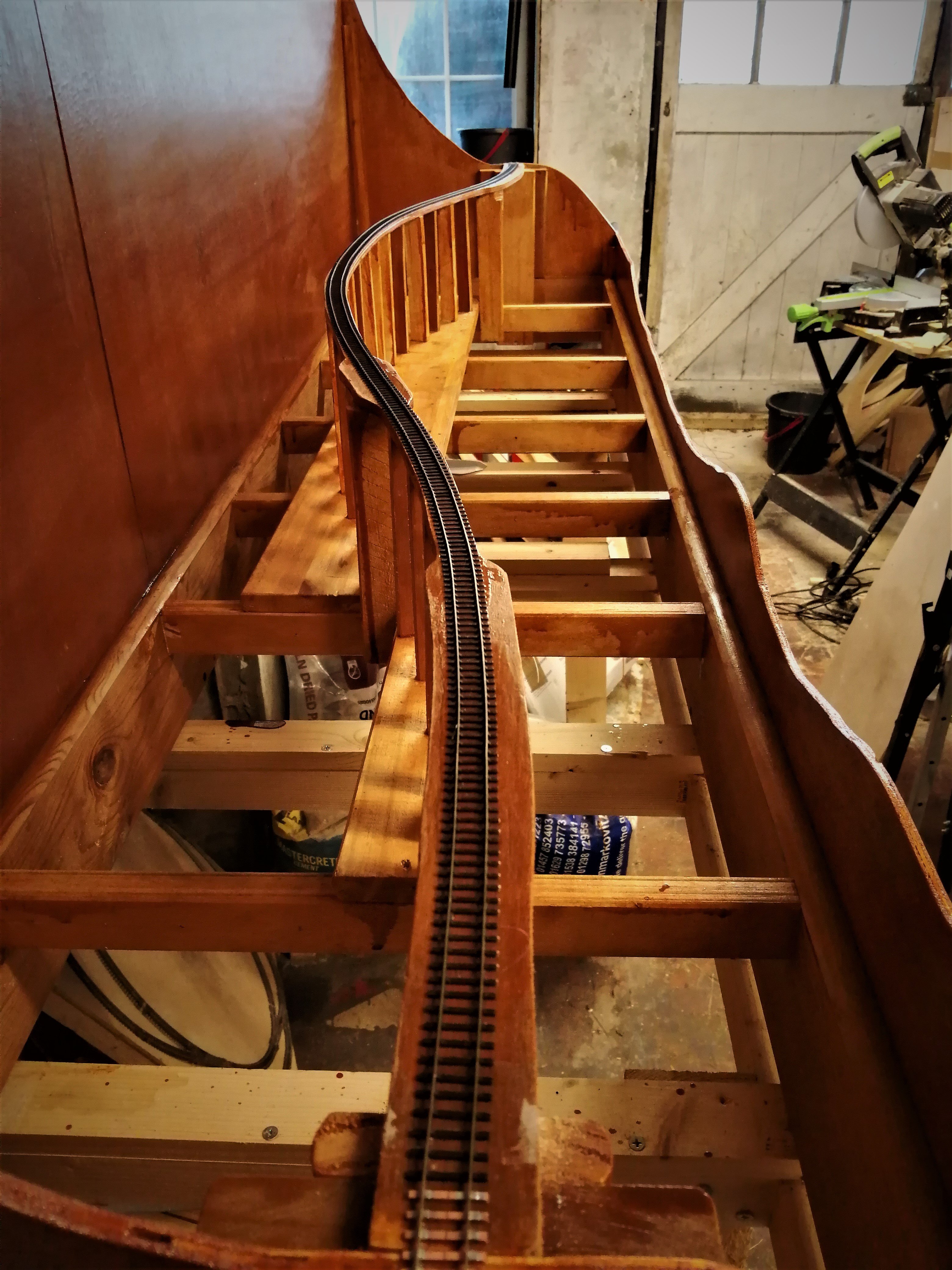
I've a semi-completed 2mm finescale "cameo layout" based on a WW1 Airship base that was built for the MRJ Cameo layout competition. This sits in the room that I use as my home office, library (it sits on top of the bookcase) and modelling room.
Although this has been exhibited a couple of times it has several shortfalls. The original plan was drawn up for a 6'6" scenic section with a 1'6" fiddle yard. This was shortened to comply with the rules of the competition to 5' scenic section and 1' fiddle yard. Being lazy, to create the shortened layout I compressed the Templot plan by increasing the sharpness crossing angle on the points and reducing the run in from the fiddle yard over the stream. I also reduced the length of the loops to suit the shortened fiddle yard.
Unfortunately the knock on effect of simply increasing the crossing angle created some unduly tight curves (I now have a better understanding of how Templot works and could have avoid this with some simple adjustments, this is user error rather than a criticism of the software). As a result anything longer then a short wheelbase wagon is derailed by the coupler loop on the DG couplings.
The length of the fiddle yard severely restricts train lengths so I find the layout a bit unexciting to operate (combined with derailing issue due to the tight radii), I also made the mistake of using a MDF base, which has misshapen slightly with the application of water for ballasting while minor, given the small tolerances of 2mm finescale, does produce a bit of annoying roller coaster effect.
The result is I seldom operate the layout, and frequently come away frustrated when I do.
I also have my Dromahair module document elsewhere in the forum.
This was started for another competition entry and generated my move into modelling Irish Railways (not a cause for regret!). I am struggling with enthusiasm to work on the module, being only 600mm long it is really being built for a one off show with limited operating potential. I am also conscious of shortfalls trying to model a real location without access to plans or a site visit to accurately capture dimensions.
My recent ponderings have concluded I need to replace the airbase layout and direct ditch the Dromahair module as it is not really fulfilling any modelling goal, but with what? I've already got my long term dream Scottish based layout underway albeit stalled awaiting garage repairs so something Irish would fit the bill. The Sligo proposal detailed in this topic would need a substantial amount of stock to be viable, this will take a long time to construct so I need to start with a more bucolic branch line so I can slowly build up stock, however, whilst we're a bit spoilt for choice, none of the MGWR termini really lit any fires.
That was until a recent post by David Holman reminded me of an Iain Rice plan based on Westport Quay. So out came the measuring the tape and a few ideas were sketched up.
During the process I became aware of a couple of photos that have offered up some inspiration.
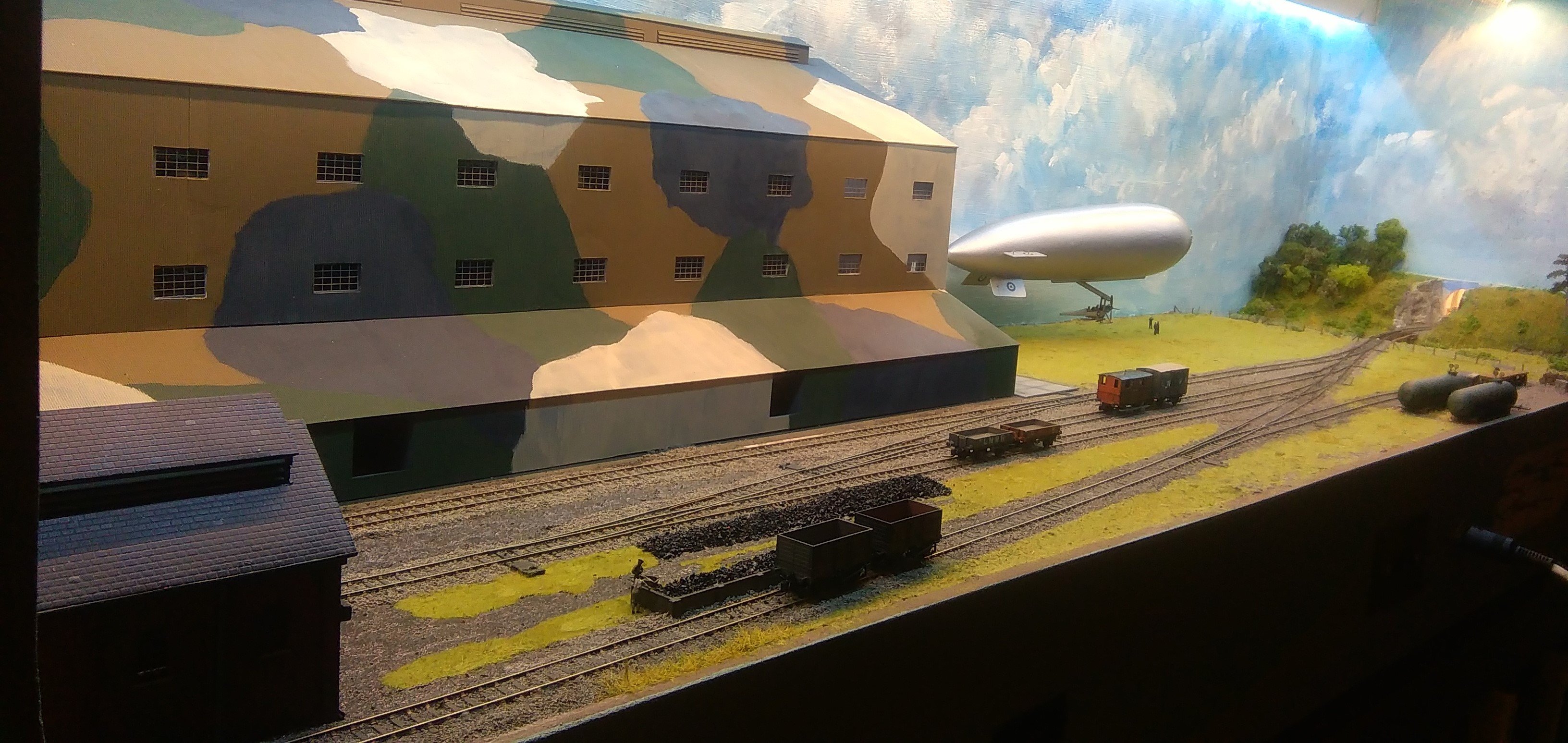
The first was of Bantry station posted recently elsewhere on this forum (apologies, I can't find the topic to link to)
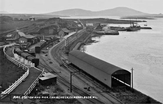
The second was the view of Cahirciveen in The Farrenfore to Valencia Harbour Railway Vol 1 (P118)
This particular photo is snipped form this online article:
https://docplayer.net/122870130-Chapter-15-archaeology-architectural-and-cultural-heritage.html
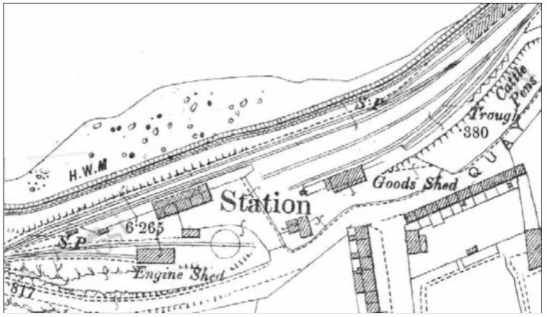
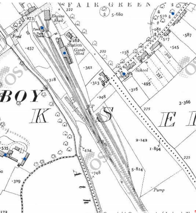
I like the juxtaposition of the harbour, the railway and the town and whilst examining the track plan at Cahirciveen
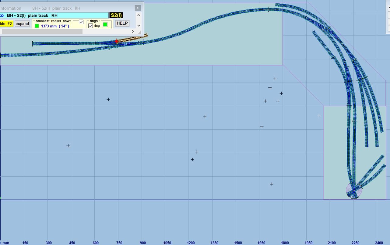
it occurred to me that with some compression it could be converted into a terminus and if a turntable release was used at the end of the run-round loop could be squeezed in to the sort side of "L" shape I have available. This would allow a bit of a longer run in and also permit another small station to be modelled, this avoiding the "shuffle on - run around - shuffle off" on most terminus to fiddle yard layouts.
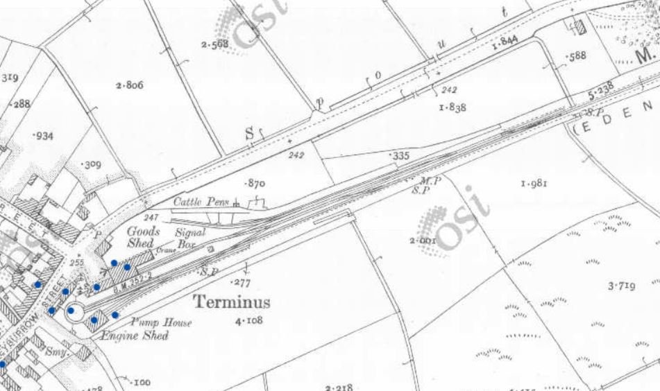
I was a bit worried about the turntable release at first but was then reassured when I found this arrangement at Edenderry:
and Athboy:
(all track plans above are lifted from the Government of Ireland's Historic Environment Viewer 25" to the mile historic maps)
Both are MGWR termini.
I've developed some thinking about where this mythical branch line would be located and some history but will follow up with that in another post.
Any thoughts so far? Is nicking a GSWR through station a step too far for an MGWR/SLNCR terminus
 ?
?
-
6
-
-
So I blew the considerable layer of gathered dust off the workbench this afternoon.
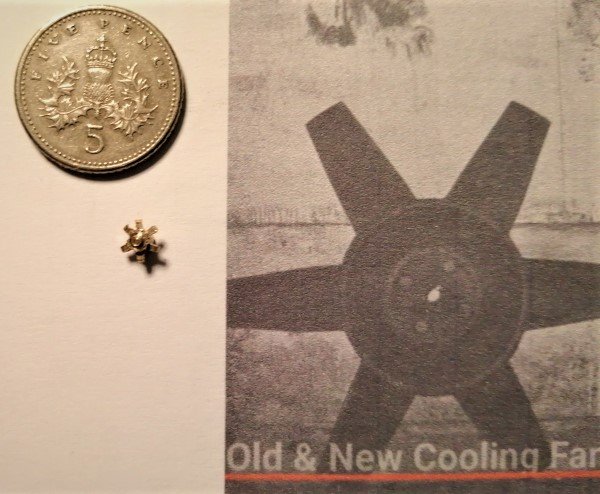
My main task was to mount a small square of stainless steel on my lathe base to enable me to use a magnetic dial gauge holder, but as I had the lathe out I took the opportunity to turn some brass rod to form the C Class fan.
After attacking it with a piercing saw and files I had something resembling the real thing, I feel I could do better but as the fan is virtually invisible behind the grill it probably wouldn't be worth the effort to remake.
The fan itself is only 4.5mm in diameter so I'm taking David's advice not to sneeze........
-
3
-
 3
3
-
-
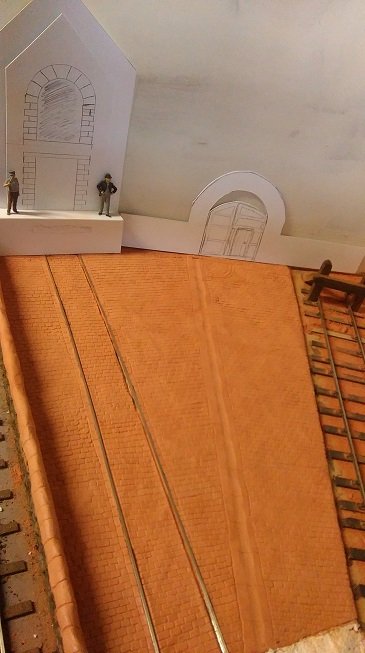
I used the terracotta colour in the photo above because the local art store was having a closing down sale and that was all they had discounted.
Yorkshire/Scottish genetics have a lot to answer for!
-
1
-
 2
2
-
-
I've used air-dry clay on a cobbled goods area for a 7mm project.
DAS is not the only show in town there are similar un-branded products around that can be found cheaper, most art supply stores carry them.
It's not really relevant unless you've a large area to do as the saving is only a few quid.
What I found works was (none of this is approach is unique to me):
- Spread a layer of undiluted PVA onto the the surface to be covered by the clay
- Break off a small blob of clay roll into a ballish shape (1-2cms in diameter) and push into the surface and flatten out.
- add the next ball so it overlaps with the previously laid one and blend in.
- use a drop of water (but only a drop!)to assist if the clay is getting a bit tough to blend.
- Keep the layers thin
- don't worry if you get a bit of cracking/crazing in the drying process, it looks disastrous but applying anther drop of water will enable you to blend out the cracks.
You've then the fun of creating the surface texture. I hand scribbed mine which was tedious at first but quickly became quite therapeutic if done in small bouts.
Hope that helps
-
1
-
 1
1
-
 1
1
-
-
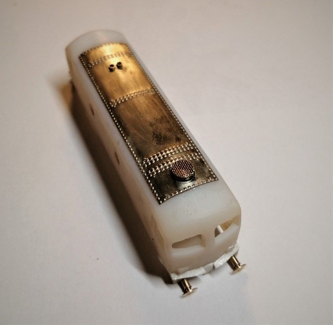
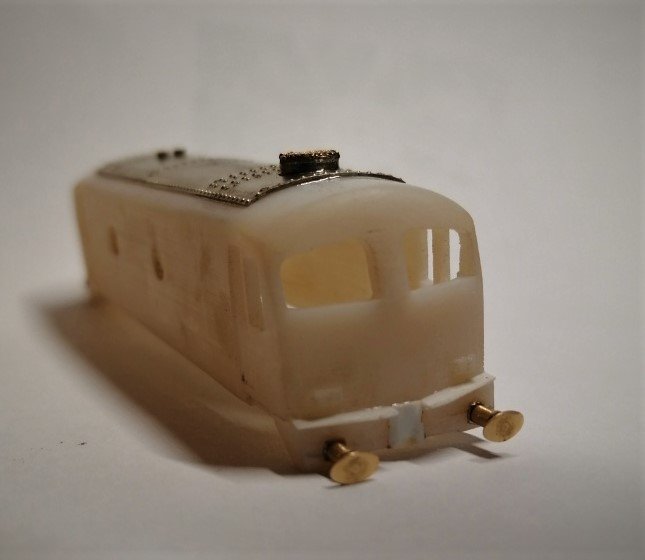
I've finally got the roof on the C Class at the third attempt.
For the first attempt I used superglue to attach the brass panel. This set too quickly and well before I could get the panel accurately positioned, so the panel was prised off and the residual glue sanded back and cleaned up.
For the second attempt I used some 5 minute epoxy, this gave me chance to clamp the panel down, but try as I might I couldn't get the ends to sit flush. So once the glue was set the panel was prised off again, the glue sanded off and cleaned up again.
After a bit of pondering I realised the problem was that plastic print was domed front to back and so raising the end of the brass roof panel at either end (I was trying to bend the panel along the length of the arch, no chance!). Whether this was a fault with the print or as a result of my sanding when I removed the roof detail I don't know, anyway, a few minute filing with a straight file result in a flat roof which the brass panel sat neatly on.
With the roof on I've added the exhausts which are simply brass tube cut to size. I did use the lathe to drill out the centre of the tube to thin down the walls a bit more first. For the fan vent I turned down the outside of the tube a few thou to create the rim then soldered on some fine mesh. I still need to make and add the centre dome and fan to finish it.
I've also got the buffers fitted. I always find that a transformational step in any build, the loco face suddenly appears. The front footplates and coupling stiffener are now fitted to one end, they still need a bit of tiding up though.
-
8
-
-
Thanks David,
In truth the 2 thou probably doesn't matter, I doubt any track I lay will be to that tolerance, temperature expansion and contraction alone would probably generate a greater error!
However errors tend to compound, so I would sooner start from the "correct" point, at least it is another variable that is controlled and hopefully the final error will still give track that is workable.
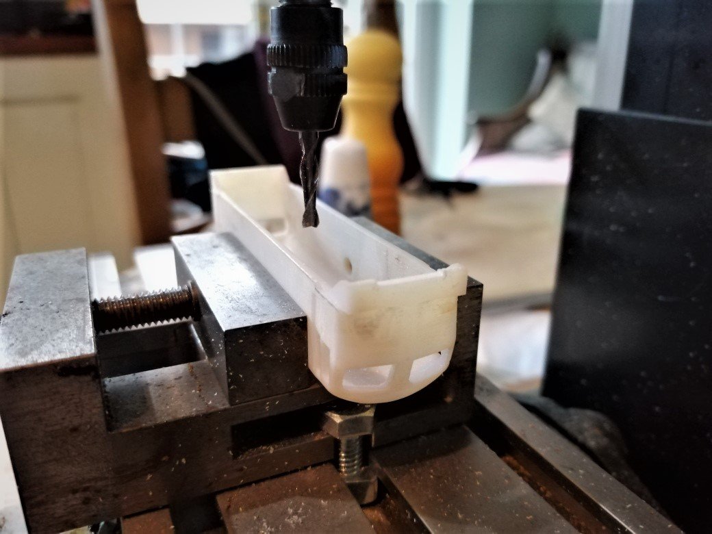
The mini mill is a Proxxon MF 70. I bought it from a store in Germany when the pound was particularly strong against the Euro (and we were still in the EU so didn't incur all the various add-on taxes). In truth I don't use it to its full potential but do find it useful to have around. I don't know how I would have created those cut-outs so neatly without it.-
2
-
1
-
-
Over the Christmas break I managed a bit more time at the workbench.
First up was a job I've been putting off for a while. A few years ago I bought a watchmakers lathe in need of a bit of TLC. Over time I've got it properly set up and working and have gradually invested in various parts (you can spend eye-watering sums on these if you are not careful!).
All my turning to date has been done with hand gravers, and whilst I have produced some loco domes and chimneys in this manner it is a slow process and difficult to make repeatable, multiple components.
I did invest in a cross-slide going (relatively) cheaply (also on need of some TLC) and whilst I'd got this working satisfactorily I couldn't find a tool holder that fitted. So, over the holidays I set too and turned and filed down one I had until it fitted, then with some shims found I could use some 3.5mm lath tools available commercially (this saves grinding your own, difficult when you don't possess a grinder!).
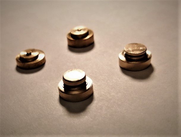
For practice I turned up a couple of button gauges, these are useful to act as track gauges on curves (they push the track apart between roller gauges) they also assist in setting the crossing nose on points.
My attempts are shown here. The ones at the back were turned using hand gravers, at the time I only had some very cheap Vernier callipers and managed to leave them way over-size rendering them quite useless. The ones on the foreground were turned using the cross slide and are much nicer, however one is just (0.05mm, 2 thou!) too thin so will need to be re-done.
I'm quite happy for a first attempt though!
I've also been addressing some of the short comings with the C Class body.
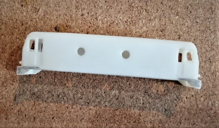
The 3d print is missing the distinctive cut aways run back from the buffer beams and finishing under the drivers door. These are particular visible in the green paint schemes I am intending as these are coloured black and contrast against the green body sides (as seen in the photos below linked from Irishswissearnies's Flickr site)
The areas that require removal are shown on the photo below. The return under the drivers door is curved so would be awkward to create with files.
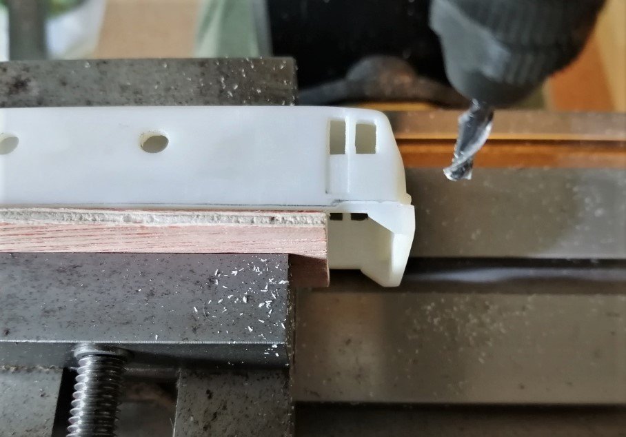
In the end I carefully set the body up in my mini-mill and used a 3mm milling bit to remove 0.5mm from the required area in stages so as not to over-stress the plastic body.
I was pleasantly surprised how successful this was, I was half expecting to be left with some melted gunk only suitable for the bin!
Whilst I was at it I also took out the notch on the underside of the buffer beam.
The body is looking a lot more C Class like now although I still need to add the footplates at the front either side of the coupling (with lamp irons) and the thickening on the buffer beam that the coupling is mounted on. Then I need to start work on the Chassis and grills etc.
-
11
-
1
-
-
Agreed Mayner, a very inspirational picture, with masses of period detail. I love the font on the Terminus Hotel!
Thanks for posting the link Ernie and hope you are on the mend!
-
1
-
 1
1
-
-
Thanks JHB, I was trying to work the logic but that explains why I couldn't find any!
-
1
-
-
A question about the C lass livery if I may JHB?
The light green line around the body only appears on some photos of the class. Was it a later addition added to all the class or were just a few turned out in such a manner with rest plain green?
Love the steamers though!
-
1
-
-
Looking forward to watching this one develop Galteemore.
-
1
-
-
Hi Galteemore, the roof in the picture was the third attempt.
In the first I didn't get the roof section square enough so the rivets wandered of the edge at the extremity from the starting point.
On the second I realised cutting the roof to size then applying the rivets was a pain in ar£e as I had to keep remounting the roof in the cross-slide making it really hard to keep everything in line.
For the final, successful attempt I cut the roof (squarely) on three sides with a waste section on the forth to enable mounting the roof in the cross-slide. All the rivets were then applied from the one fixture and the excess brass cut off later
All part of the learning curve. Thankfully this time my learning curve wasn't flat!
-
1
-
-
Agree about the rivet press Galteemore. It's a great piece of kit and a pleasure to use. I just wish mine was as shiney. I made the mistake of leaving it in a damp garage for a few months so it quickly became covered in a coating of rust that took some cleaning!
-
1
-
-
A while ago I was gifted a 3D printed C Class body. I've always liked these little diesels and found them very charismatic so I've been contemplating what to do with it.
I've bought a Tomix chassis which is dimensionally close to the prototype dimensions, the bogie wheelbase is correct but the bogie centres are 2mm (a scale foot) to close together. That's a compromise I can live with. I still need to fit the correct diameter wheels to finescale standards and widen the gauge to 10.5mm from standard N.
The body looks to be an old print, I'm not sure what the material is as it is tough and flexible rather than usual hard and brittle product from the likes of Shapeways. it certainly is not a modern resin print! It does suffer from striation in the print, which given the smooth sided appearance of the real things needs work.
Looking closely at the body the details are quite naïve and also in need of improvement.
I was struggling to find detail shots of the locos, particularly in original Crossley engined format which is the version I want to model, there are plenty of 3/4 photos in the stunning Irish scenery but roof shots in particular are hard to come by. There is a drawing widely available but not the most detailed:
So I was struggling a bit until I found this little gem:
This clearly shows some great detail on the roof and some interesting comparisons between the pre and post engine conversion body detail. The drawing above for example appears to have the post conversion roof vents but with the earlier sized radiator grills and fan housing. I had never appreciated the difference in size of the fan!
I decided to bite the bullet and remove all the detailing from the body (barring the marker lights). This made sanding the body back to a smooth surface relatively easy. A couple of evenings measuring up the various detailed photos got me a set of dimensions that check out against the various sources so reconstruction could begin.
First task has been to recreated the roof panels from a single piece of 10 thou brass sheet. This is the first time I've used the cross slide on my GWR rivet press in anger, but I'm pleased with the result. The rivet impressions are probably a bit oversize, but again a compromise I can live with, I've also drilled out the lifting eyes, fan housing and exhausts. These can be fitted once the roof panel is attached to the body.
I just need to roll the roof panel to the correct profile for the body (which is proving a tad tiresome!)
-
5
-
1
-
-
Hi David, I've since found the article, it's issue 227. In it Gordon uses newspaper covered in dilute PVA. The texture is less corse and the wet paper hangs and draps more effectively.
He covers the wagon in clingfilm first mind, otherwise it would be reduced to a gloopy mess.
As regards resin casting I was wondering about the approach you outlined. I might still give it a go but in all honesty for small scales such a 2mm I think the 3d resin print will work better.
-
1
-
1
-
-
Thanks Ken, I'm just happy to be doing your design work justice.
21 minutes ago, Galteemore said:a great way to build up a mixed train quite fast
I've been pondering how best to build the fleet of SLNCR cattle wagons I will need. I didn't fancy scratch building multiple vans so have been reading up on resin casting, however I'm now convinced that 3d printing is the way to go (certainly for small scales anyway). I just need to get on with it!
-
2
-
-
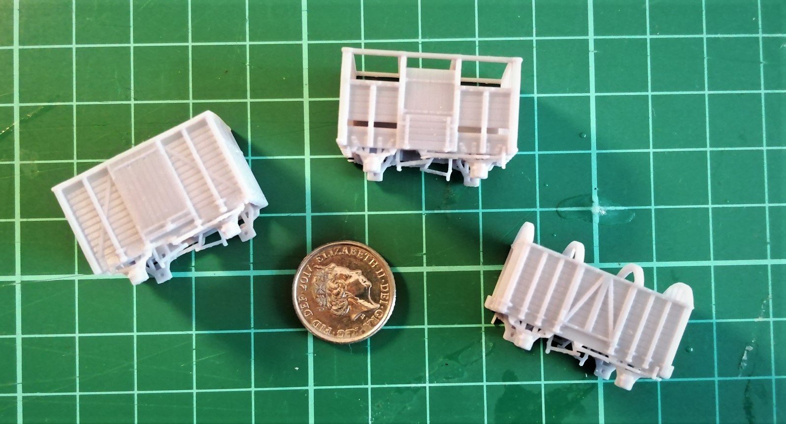
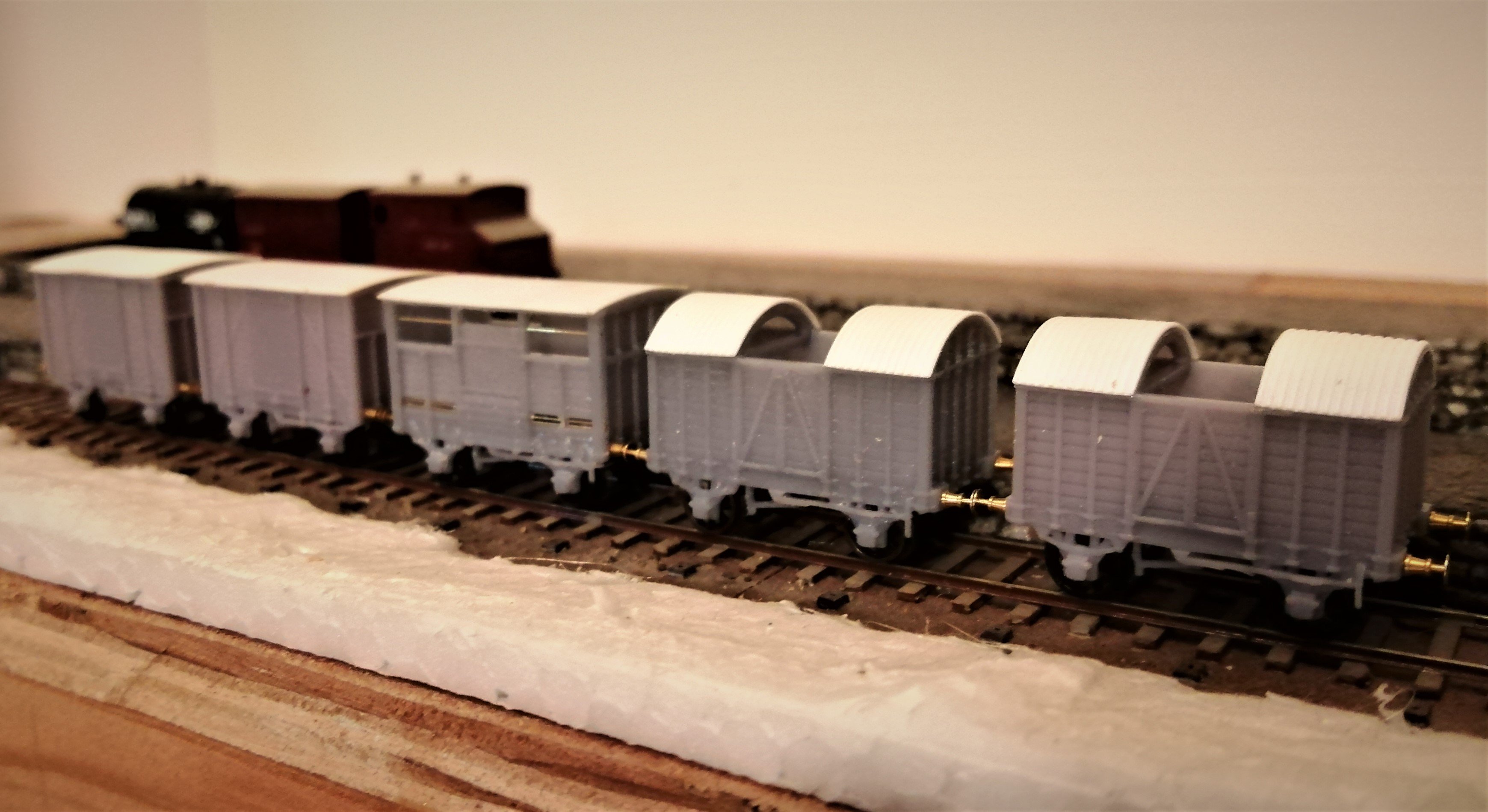
As I've mentioned in his work bench topic I reached a deal with KMCE to send me some his 3d printed 4mm Vans scaled down to 2mm.
The Postie arrived with these gems on Wednesday:
Unfortunately work commitments got in the way of playing, other than taking them out of the box, but with a free(ish) weekend thanks to the weather I spent some time at the bench getting the vans ready for painting.
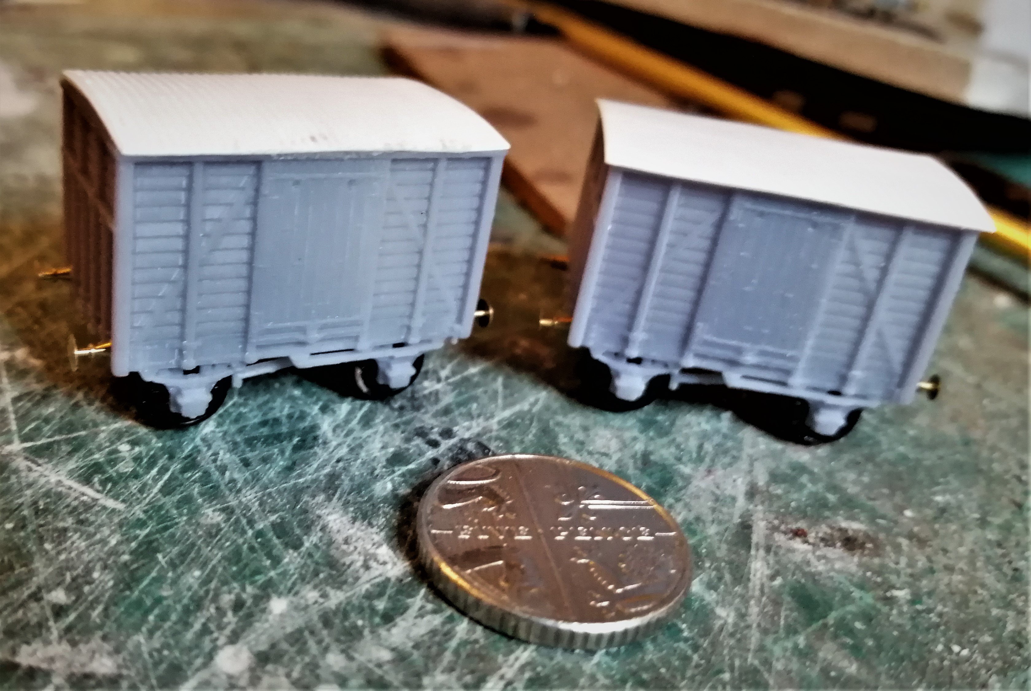
For the short wheel base vans I've used the photos in Rail to Achill as a guide, the vans are slightly different to those photographed but I've followed them anyway so one has a corrugated roof and split spoked wheels whilst the other has plain roof and plain spoked wheels. Apologies for the poor images, it's been hard getting enough light on the models, the white rooves don't help with focusing either.
As an aside, were the corrugated rooves painted, or just left as plain galvanised sheet? It would seem a bit pointless to paint them.
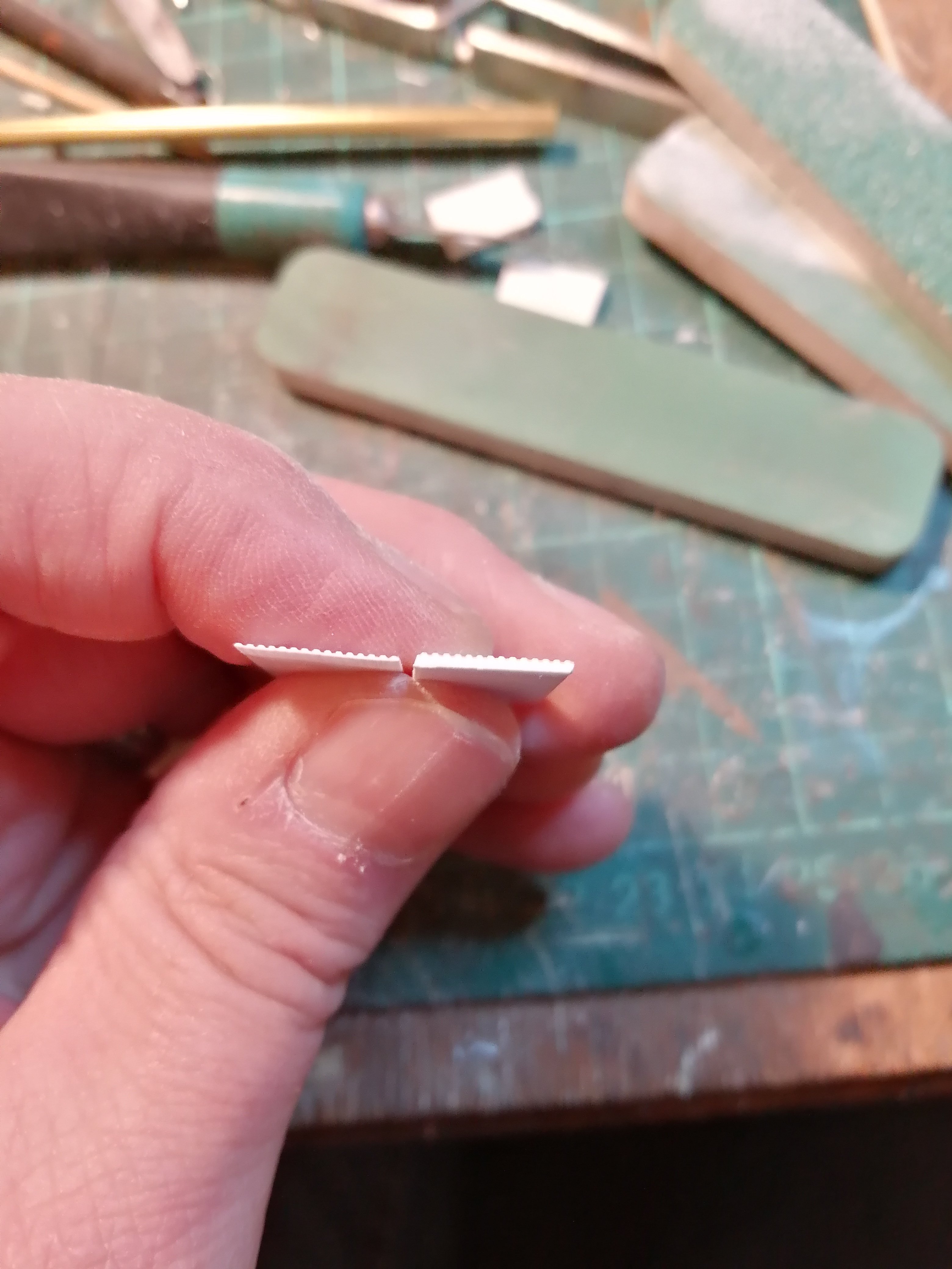
I'm pleased with the bars on the cattle truck, KMCE has printed dimples to locate the drill holes which makes drilling them and fitting the bars a doddle, the top bar is 0.3mm and the bottom two 0.2mm
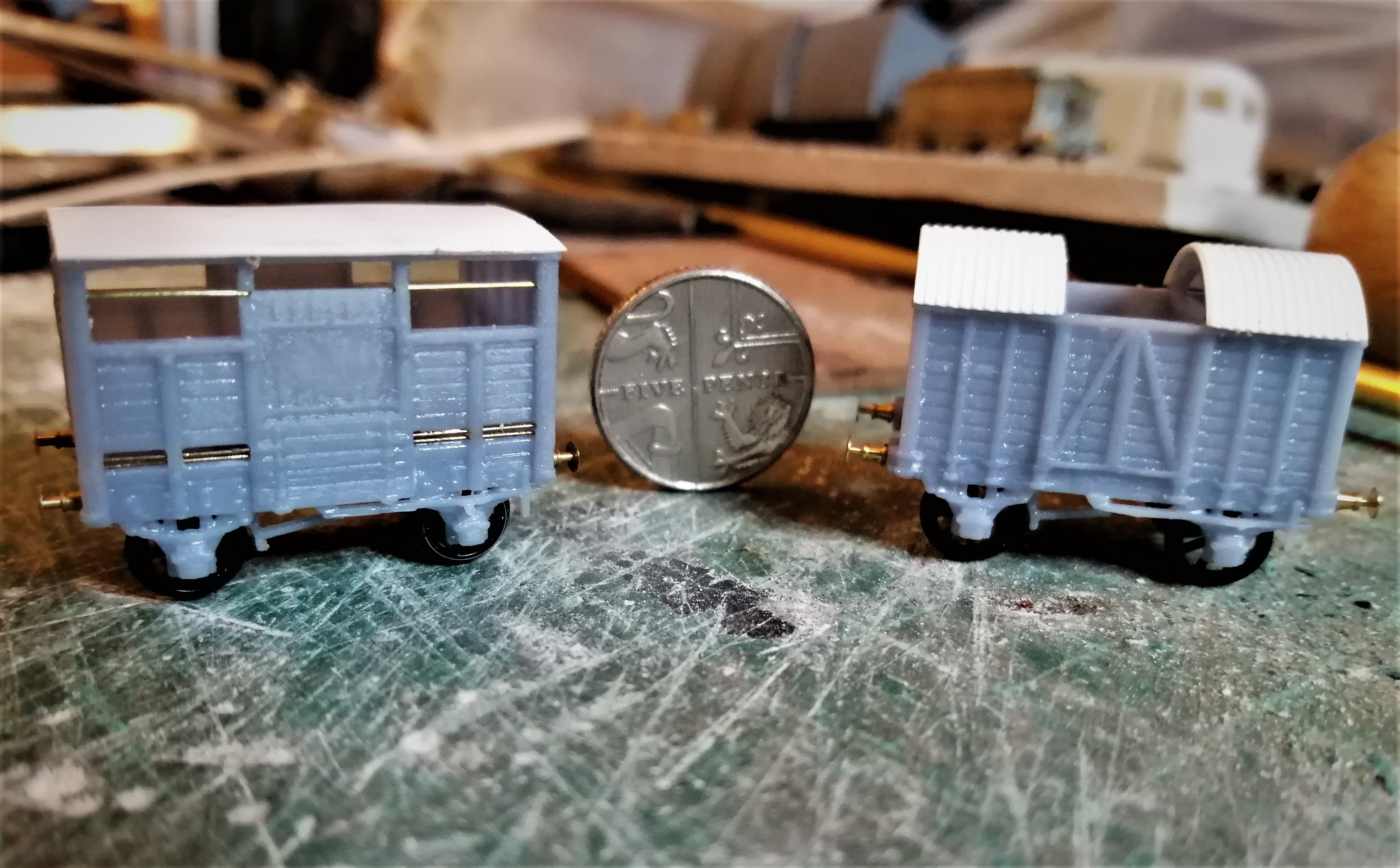
For the corrugated rooves I pondered a bit, I thought about using silver foil formed on a corrugated sheet but figured this would easily prone to damage. In the end I just thinned down some corrugated plastic sheet I had to hand, it was about 2mm thick so need thinning right down to bend to the curve of the roof and look the part. The corrugation are a bit wide mind.
I need to work out how to make the canvas covers for the middle, I've previously used a technique described by Gordon Gravett in an edition of MRJ a few years back for some 7mm scale wagon tarps, I'm just struggling to lay my hands on the copy.
All told I pleased with result, I might add a bit more detailing, some of the rivet detail is a bit lost (this is 2mm scale so asking a bit much of the printer to produce full rivet detail) which I might add using rivet transfers, and there are some grab handles to add but a couple of afternoon's work to produce five wagons gives my Irish Stock a much need boost. If I was building these from a kit or scratch I doubt I'd be half way through the first van by now. I was worried this might feel a bit too much like "open the box" modelling, but there was enough to do to make it interesting. I'm definitely sold on 3d printing now (even if does mean re-learning CAD), I just need to save my pennies.
I've still another cattle van to do but have run out of wheels, so that will have to wait for another day. Just need source some decals now.
-
3
-
3
-
-
13 hours ago, Angus said:
They almost look as nice as the 2mm scale ones Ken
 11 hours ago, jhb171achill said:
If you were ever able to scale down the "soft-top" and the goods van I'd be interested in a few.
To 00 scale, that is.
I think I may have caused some confusion with my top comment so I had best elaborate, Ken sold me some of his 3D printed vans scaled down to 2mm scale. They arrived mid-week so I've not had chance to do anything with them yet.
There's snow on the ground here so my cancelled bike ride tomorrow may allow time to play.
-
6
-
-
They almost look as nice as the 2mm scale ones Ken
-
1
-
1
-
-
16 hours ago, Angus said:
I'll have to spend some time trawling the photos.
A quick look through Neil Sprinks's Irish Railway Pictorial of the SL&NCR shows a surprising number of these "to run passenger trains" boards once you know to look for them. In most of the shots with cattle vans there are at least one or two vans that have the boards.
There is a photo of the 7.20Pm mixed from 1950 on page 23 of the book where the first four cattle wagons have the boards.
Definitely a nice detail to include (once I get around to modelling some of the wagons!).
-
1
-
1
-
-
Well that's at least two cattle wagons with them on then.
I seem to recall that quite a few of the SLCNR cattle vans were vacuum braked. I'll have to spend some time trawling the photos.
-
2
-


.jpg.e87d4a96e652611d709eb19e7f385f35.jpg)


The Sligo to Larass branch of the MGWR (with a bit of help from the SLNCR)
in Irish Model Layouts
Posted
Indeed and also well represented in Mr Rice's writings. The timber bridge on my airship base layout is based on the one on on the Kirkcudbright branch. Plenty of inspiration there!