
2996 Victor
-
Posts
348 -
Joined
-
Last visited
-
Days Won
2
Content Type
Profiles
Forums
Resource Library
Events
Gallery
Blogs
Store
Community Map
Posts posted by 2996 Victor
-
-
So sorry to hear your news, Ken - along with everyone else, I'm sending you all best wishes for a speedy full recovery.
Stay safe and keep strong.
Mark
-
 1
1
-
 2
2
-
 1
1
-
-
9 hours ago, David Holman said:
Hope you didn't do what I did when researching how to paint my nuns. An internet search resulted in some very interesting suggestions of how to dress up for the weekend!
Did it involve parachutes?
-
1
-
-
27 minutes ago, Patrick Davey said:
He says the electricians who work at the mill are all wired up anyway. He nearly blew a fuse when these lights didn’t work so he sent them all ohm.
Groan

-
 3
3
-
-
Stunning work! And +1 on the tutorial - that's a brilliant technique.
Cheers,
Mark
-
1
-
-
Brilliant, David! Maggie is the G.O.A.T. goat
")
Cheers,
Mark
-
1
-
-
44 minutes ago, David Holman said:
Thanks Mark, had been thinking about that, but getting the fibres to fall the right way could be difficult. The model is only 3cm long and there's a danger of over doing things!
Worth a try though.
Yes - you'd have to "brush" the fibres soon after applying them to mimic how the real animal's coat lies. Although the "plugged into the mains" look would be quite funny.....

Or, after you're absolutely happy with the goat's shape, what about a very thin final covering of thinned clay more like potter's slip but not quite as runny. Then use a toothbrush or similar to brush in the goat's hair while it's still damp.
Perhaps a trial on a spare lump of clay might be worthwhile!
Cheers,
Mark
-
 1
1
-
-
9 minutes ago, David Holman said:
so am currently pondering how I might represent that.
What about using fairly short static grass fibres? Apply in the usual manner, and gently smooth flat like the animal's coat, perhaps with a soft paintbrush, before the glue dries. When dry, lightly airbrush over with goat-colour paint.
Cheers,
Mark
-
1
-
-
7 hours ago, Galteemore said:
That’s really annoying Mark. Hopefully you will get something sorted.
Thanks
") it's more annoying because of the time wasted - I should have bitten the bullet and built my own to begin with.
it's more annoying because of the time wasted - I should have bitten the bullet and built my own to begin with.
At least it'll be good practice for the 21mm gauge track for Mount Bellew!
All the best,
Mark
-
1
-
-
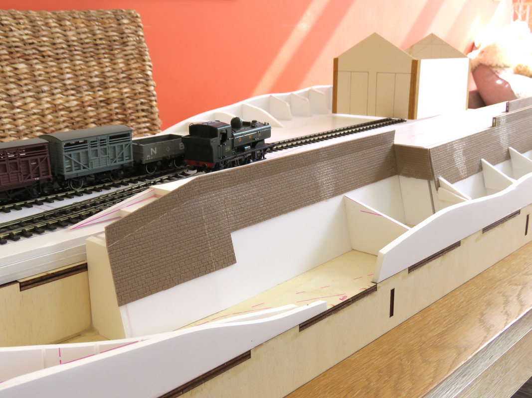
Just a short non-update on Yeoman's Wharf.
I'd got to the stage where I really needed the track in place before I could go further with the structures and scenery.
I think I mentioned outsourcing the pointwork to a professional builder as the geometry is non-standard and I want avoid the toylike look to the track.
Well, the pointwork arrived at the beginning of the week after four months. To say I'm disappointed is an understatement: tie bars loose, rail heads filed to get them level, check and wing rail leads filed not bent, and very messy soldering throughout.
I know I should really go back to the builder but I just want to cut my losses and move on. With hindsight, I would have been better off using the intervening period to learn the skill myself. Shoulda', coulda', woulda'!
I hope to have some good progress to report soon.
Cheers,
Mark
-
4
-
-
12 hours ago, jhb171achill said:
I have found that setting features in place first, then taking pictures of them in black and white against a backdrop of a wagon or locomotive, tends to show up very starkly whether they’re about right or not.
What a brilliant idea! I have awful difficulty in gauging the relative proportions of landscape features to the point where I end up with either rapid erosion or orogeny to correct massive errors of judgement!
Great photos of the goods train in the evening sunlight, very evocative.
Cheers,
Mark
-
2
-
-
1 hour ago, Patrick Davey said:
Now I am extra gutted. I had hoped that Cultra would be my first outing with Brookhall Mill but I have to work that day

And now I’m going to miss Fintonagh too…..

-
3 hours ago, Northroader said:
I should try to progress jobs, finish stuff off, then another bright (?) idea hits me.
This is my story, too! I've six or seven aeroplane kits in various stages of being built, the 009 layout in the British section on here, and two EM Gauge micro layouts on the go as well. Then I've been bitten by inclined planes and the London underground railways at the turn of the 19th/20th centuries.
Nurse! My medication, please.....
Cheers,
Mark
-
3
-
1
-
-
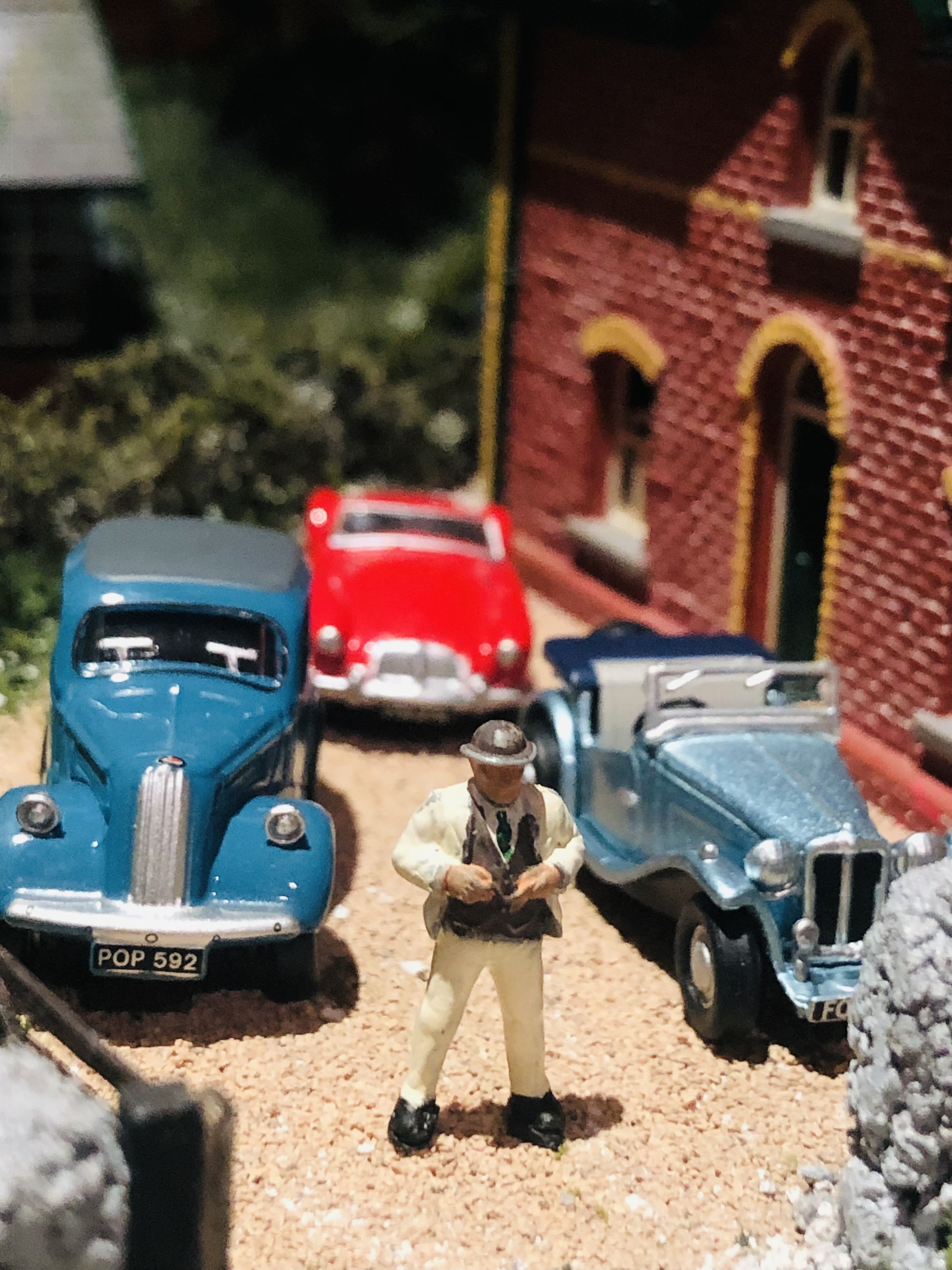
10 hours ago, Patrick Davey said:Mr. Weaver was very proud of his vintage cars:

That's a rather nice MGTD on the right
Cheers,
Mark
-
1
-
-
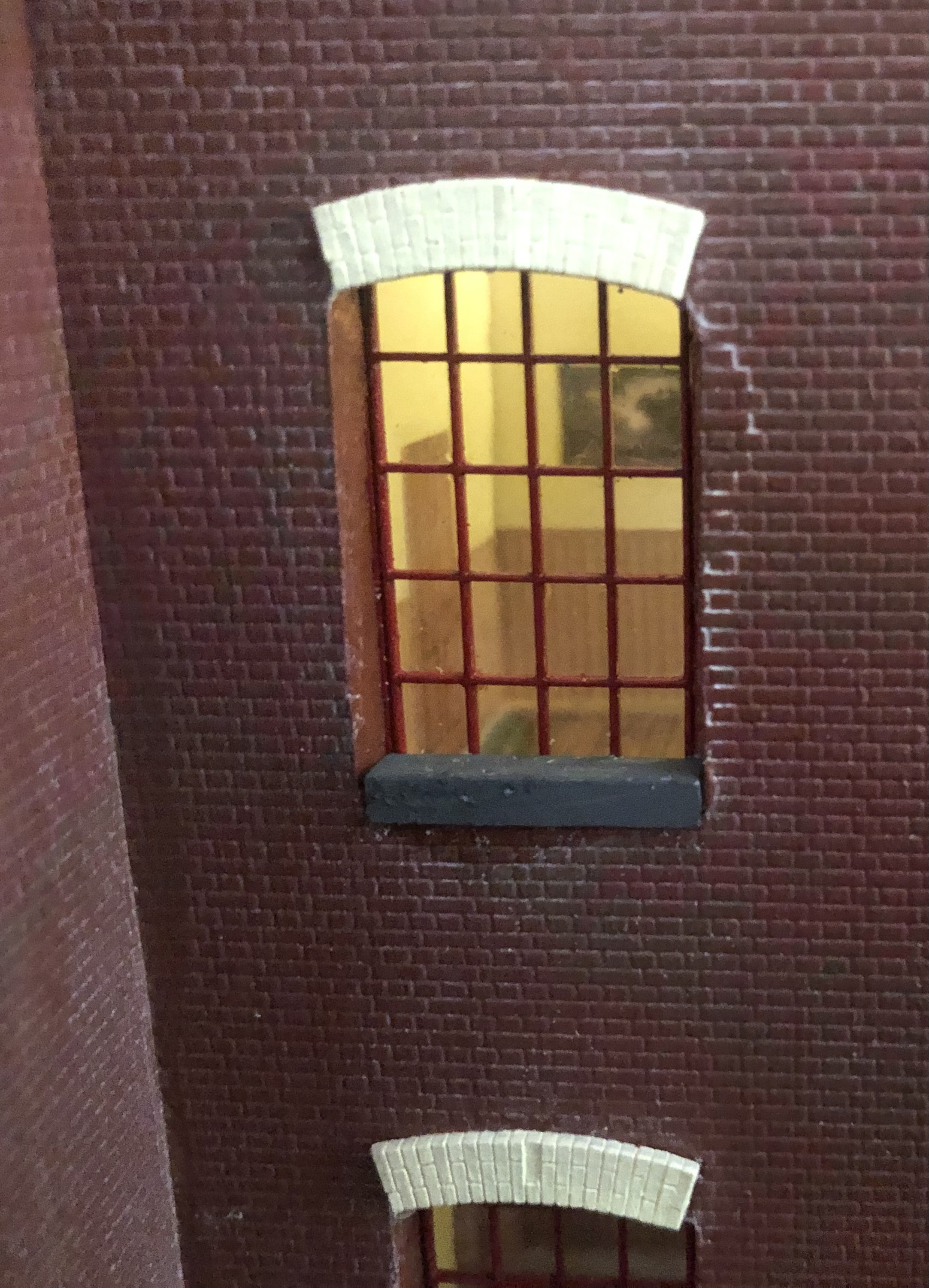
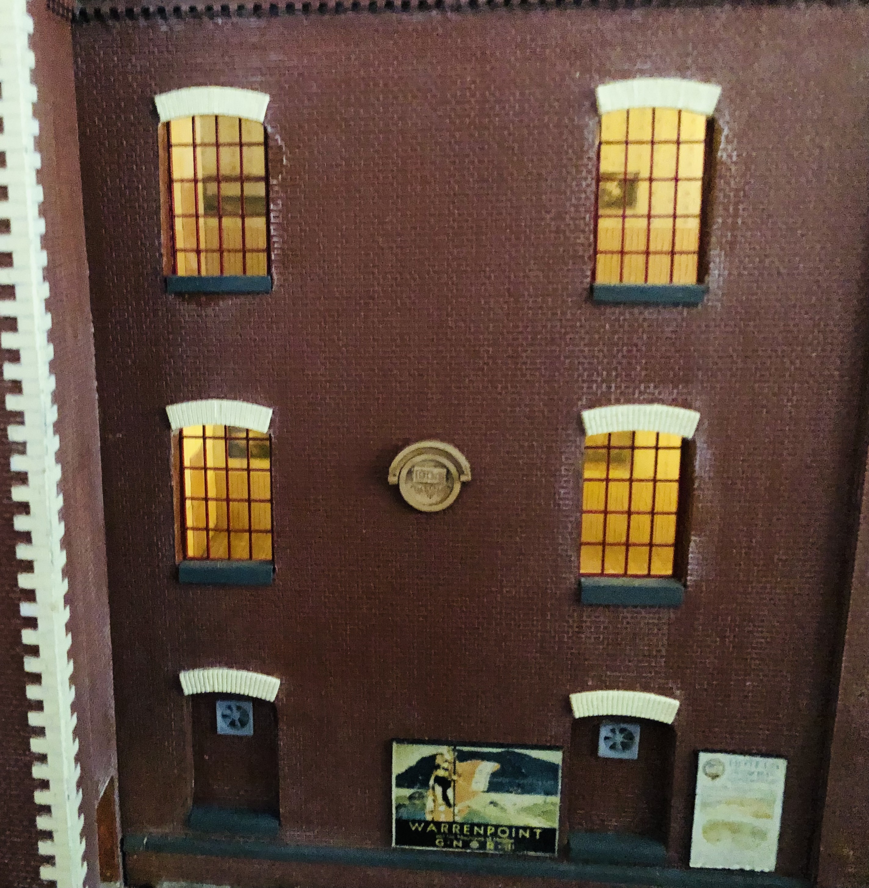
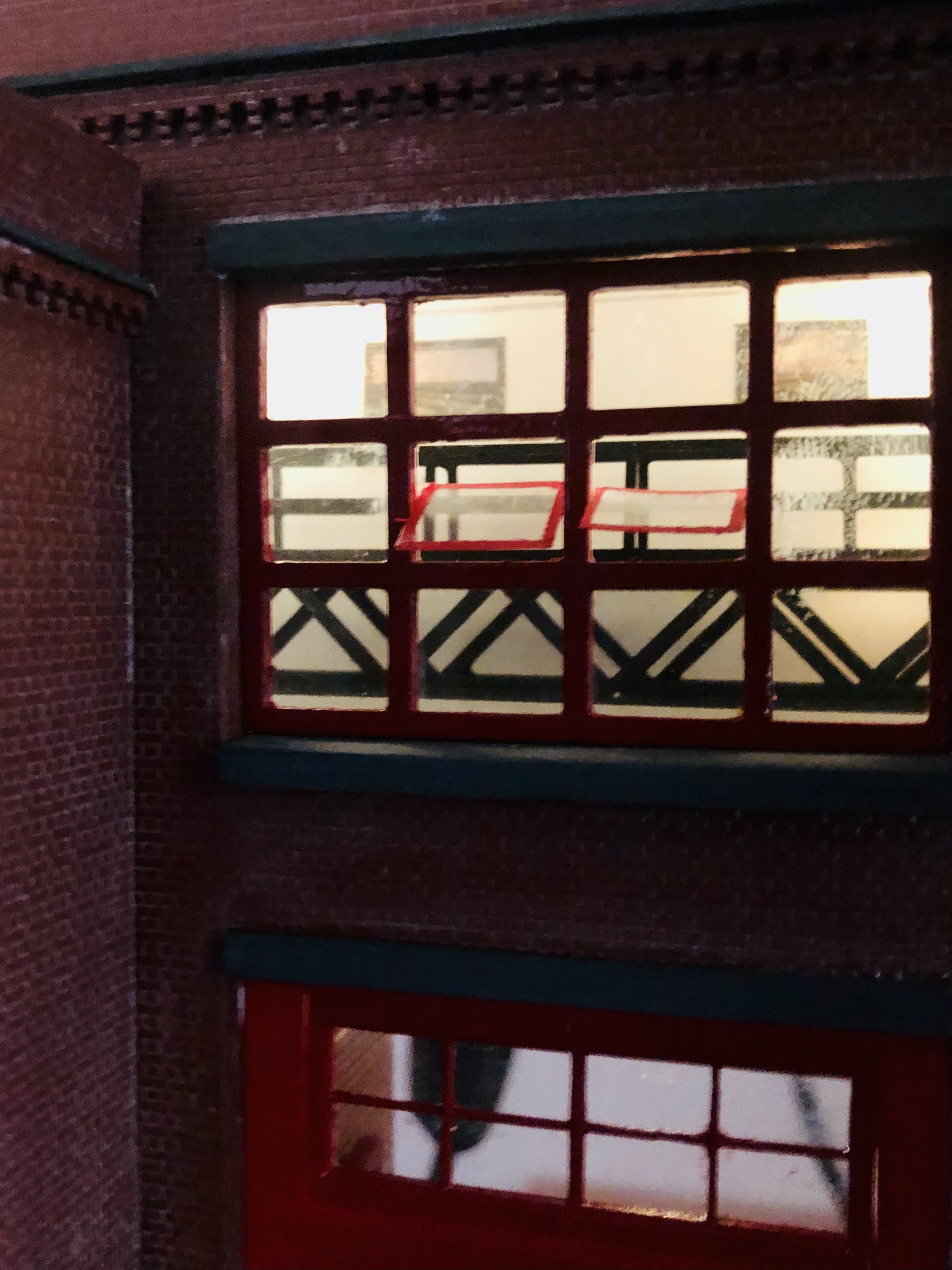
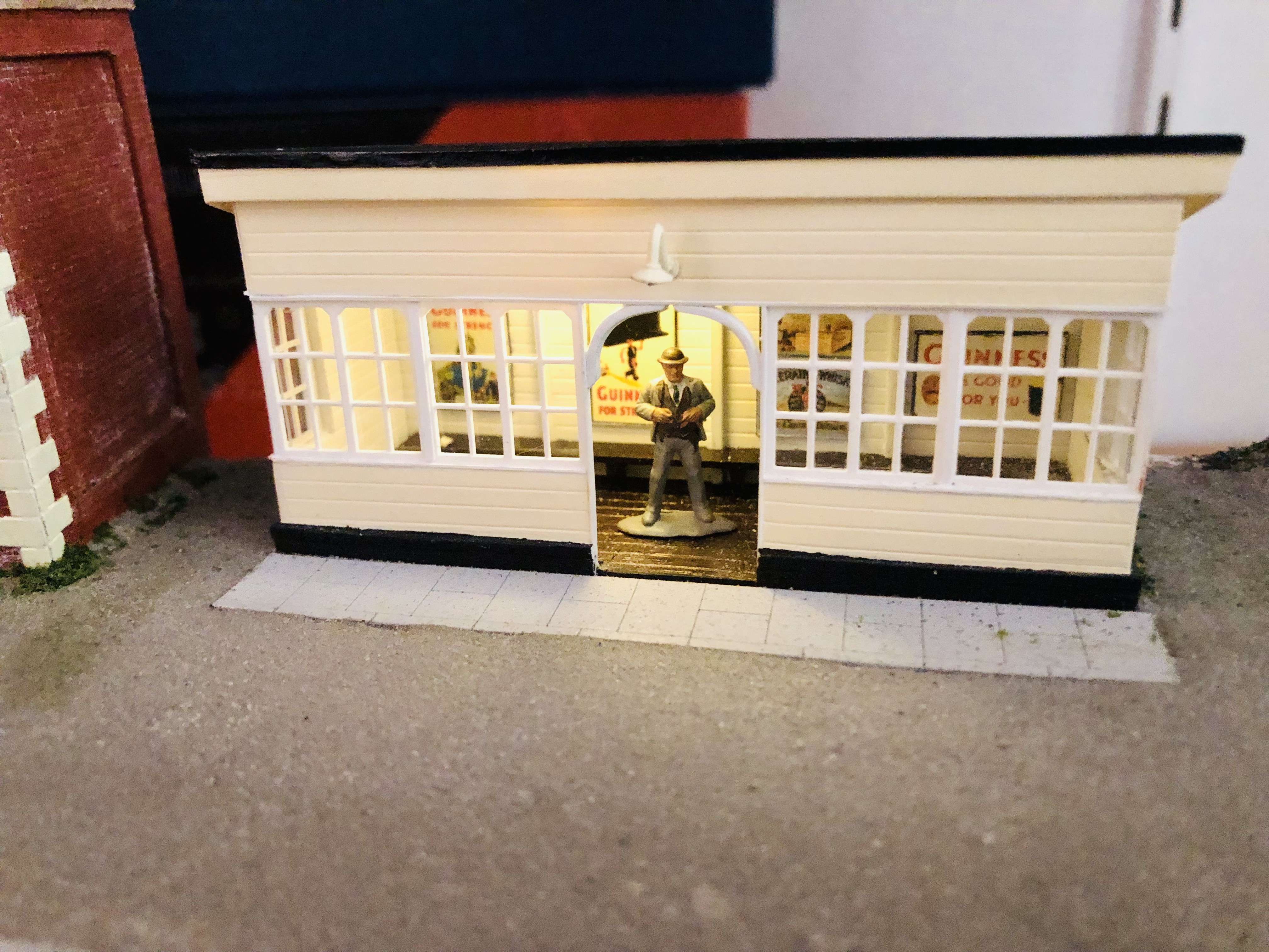
51 minutes ago, Patrick Davey said:
Been working on the interiors of the mill buildings recently, and experimenting with lighting. Lots of fun that!
Fantastic work - lit, detailed interiors look so good!
Can you post some details, please? I found a great article in a previous Railway Modeller about water colour tinting a drawn, fold-up interior.
All the best,
Mark
-
2
-
-
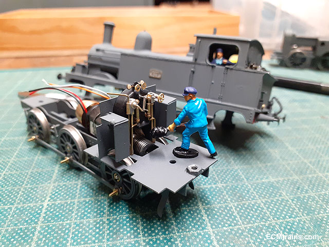
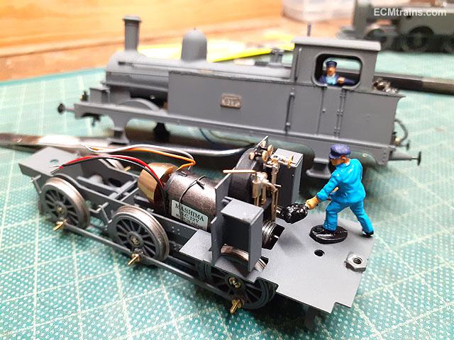
5 minutes ago, murrayec said:
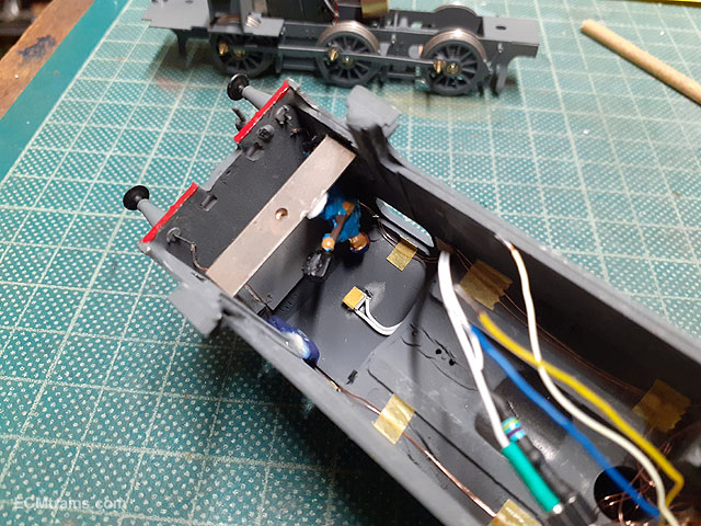
On the final stretch now!
After assembling the chassis and giving it a test run to adjust the coupling rods the driver and fireman turned up to lend a hand.
After checking the fit of the fireman he was then epoxied onto the body-to-chassis fixing bracket, a LED cab light was also fitted. A bit of masking tape is placed over the LED to dull and yellow the light.
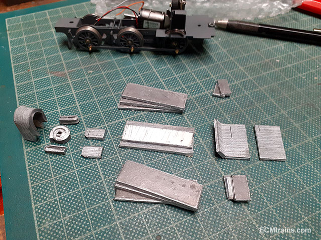
About 100 grams of lead weight was chopped up- sized to fit on the inside of the body. The main weight being centred over the back axles.
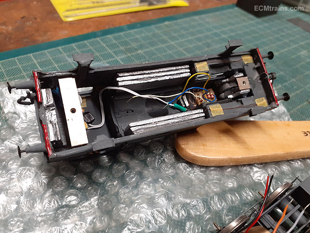
Weight epoxied in.
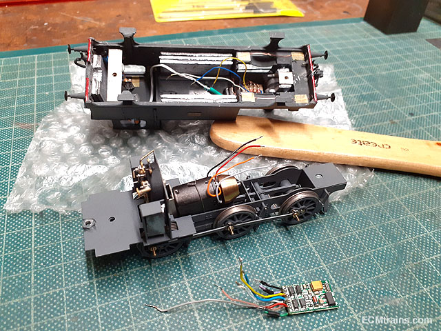
The final problem- fitting the chip and wiring in there somehow........
Phenomenal! Absolutely amazing modelling!
Cheers,
Mark
-
1
-
 1
1
-
-
21 hours ago, Kevin Sweeney said:
Thanks for the tip, it sounds easier to work than plywood.
It is! Much! I'd definitely recommend it.
I've been covering the foam board formers with a lattice weave of wall paper lining paper, and then four layers of newspaper strip papier mache. It makes a pretty strong shell.
Cheers,
Mark
-
2
-
-
16 hours ago, Kevin Sweeney said:
On the northern end the ground will rise 10 mm to the NW corner and drop 14 mm at the NE corner. The trackbed will remain flat. I'm not sure yet how I'm going to create this non flat landscape, but I'm experimenting with plywood templates, to give me the basic shape
I've been using 3mm and 5mm thick foamboard on my 4mm/EM micro:
This was a while ago and things have moved on a bit, but you can see the foamboard profiles. Easy to cut with a craft knife or scalpel, glued with Javis VeloSet quick setting PVA. Its light and strong and its easy to carve if you need to modify it once its in place.
I've got mine from a seller on eBay - this is the link to the 3mm foamboard https://www.ebay.co.uk/itm/272000832907
Looking forward to see your progress!
All the best,
Mark-
3
-
-
Many thanks - that's great advice.
I'm modelling to EM standards so not quite as fine as they could be, but still needing care! I think I can get away without suspension with careful track laying on rolling stock: items built so far seem to bear this out. But I would be happier if my locos have all the help possible in keeping their feet firmly planted!
All the best,
Mark
-
2
-
-
2 minutes ago, jhb171achill said:
I can’t answer that as I have zero knowledge of the process, but it seems like a simple issue to solve.
I think there can be limiting issues with print design and material type, but I would've thought in this scenario it wouldn't be an issue. Cost may be factor, though.
-
1
-
-
Beautiful loco and interesting solution to the balance problem.
Being a novice engine-builder with a grand total of zero completed locos, I was wondering if there would be any scope to run the drivers rigidly in the frames, and beam compensate the carrying wheels. I imagine space would be the limiting factor.
Cheers,
Mark
-
1
-
-
I've got some of Scale Model Scenery's weathered slates to try. They look really very good on your buildings - I'm looking forward to giving them a try!
The DAS flashing and rain streaks are particularly convincing.
Cheers,
Mark
-
1
-
1
-
-
On 11/8/2022 at 11:18 AM, jhb171achill said:
True.
I do recognise that a huge investment in time is necessary to produce these designs, but I am also aware that there is ample technology now to 3D print things to a much, much higher standard.
Absolutely! When I first raised my doubts on my RMWeb thread, the first question asked by a guy who knows 3D-printing inside-out was, "What material was it printed in?"
I can't remember what the material was, but when I answered, the response was, "That's the problem - it's the wrong material for a good finish and fine detail. People don't use the right materials for the job!"
I wonder how much better RC21's prints could have been with just a change of material type.
Cheers,
Mark
-
6 hours ago, jhb171achill said:
That seems to be a general consensus, unfortunately!
A great shame

-
1
-
-
On 5/8/2022 at 6:44 PM, Pete00018 said:
I don't know about the broad gauge ones, but I've a number of narrow gauge Rc21 Shapeway prints and so far they have been goods quality. The usual steeping, washing and rubbing down before priming. Fingers cross the next one has no issues..
A given tho that not as detailed as brass kits.
It would help if accurate drawings were to have for producing 3D CAD and prints.
Best regards,
Peter
Many thanks, Peter, that's good to hear.
The items I've had were narrow gauge as well, the War Department Class D bogie open wagons, which as mentioned were dimensionally seriously in error, and also some 009 wagon turntables. The print quality was really quite poor. I mentioned the quality of the prints on another forum, and the consensus from those who know about such things was that the choice of printing material was wrong.
Hopefully my experience is in the minority - he has many items that I'd be very interested in otherwise.
All the best,
Mark
-
1
-
Port Bréige
in Irish Model Layouts
Posted
Fantastic news, Ken - keep at it!
Some lovely little bits of progress on the Port, its the details that make the layout come to life and its certainly doing that. I do like Dart Castings products - their conical milk churns for instance are, imho, the best available (no association with them except as a satisfied customer). I don't think I've said before that I think the Maltings are superb, although all your buildings are excellent.
Nice convertible, by the way")
Stay safe, keep strong, and keep getting yourself better")
All the best,
Mark