

murrayec
-
Posts
2,568 -
Joined
-
Last visited
-
Days Won
67
Content Type
Profiles
Forums
Resource Library
Events
Gallery
Blogs
Store
Community Map
Posts posted by murrayec
-
-
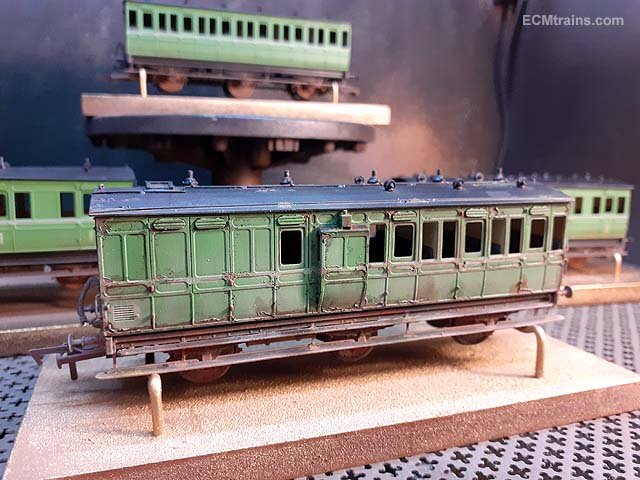
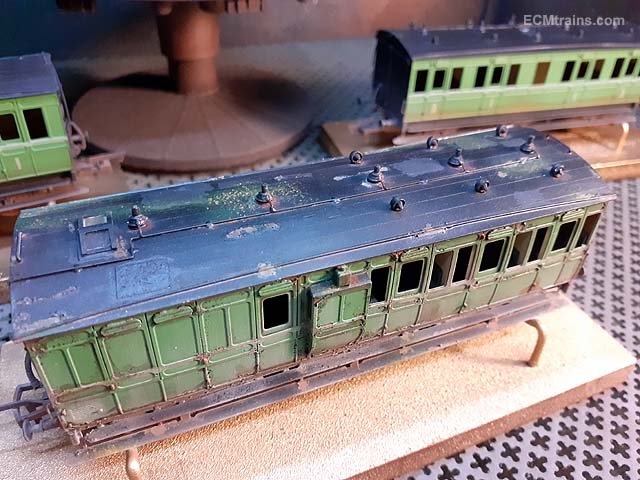
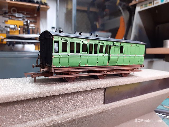
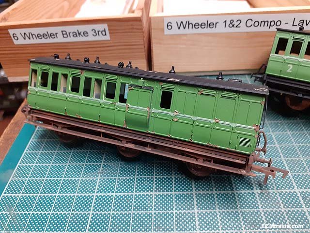
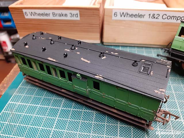
Weathered and lacquered over the last couple of days;-

This build has taken so long that moss & lichen have taken to the roof of the brake van!!
Door handles and glazing next
Eoin.
-
 6
6
-
 2
2
-
 2
2
-
-
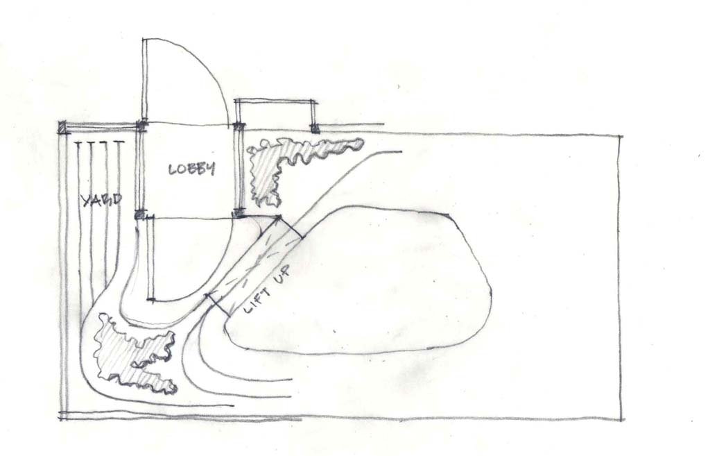
A Lobby;-
Eoin
-
5
-
-
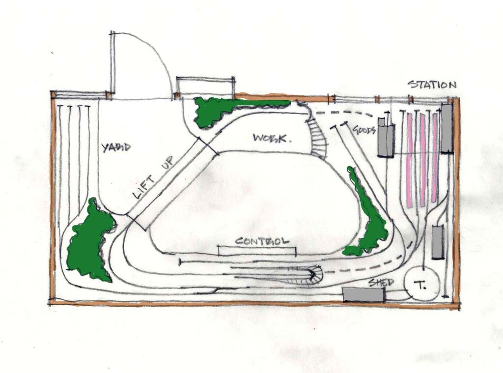
Here is one to kick off the discussion;-
Taken from Mr CJ Freezer's 'Track Plans' Plan No. 1 for a small bedroom!
I have elongated it to suit your dimensions and ignored your lobby, I reckon railway layout space is more important than a lobby.
This plan allows for a train to run on a loop, which runs under the station, so then one can play end to end between the fiddle yard, the goods, the engine shed, and the station at the same time. The trains would have to reverse into the station and would be short!
Eoin
-
6
-
 1
1
-
-
-
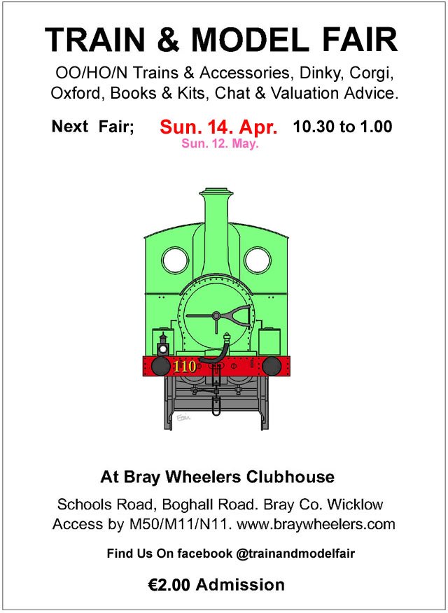
April's Fair Date;-
-
2
-
-
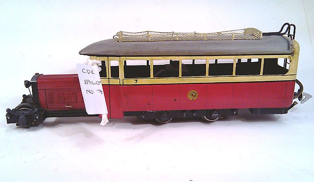
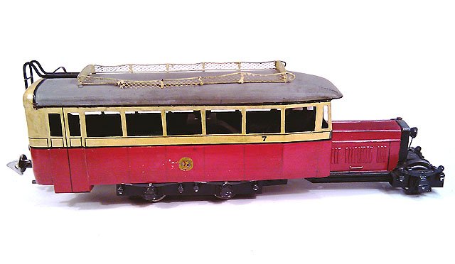
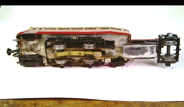
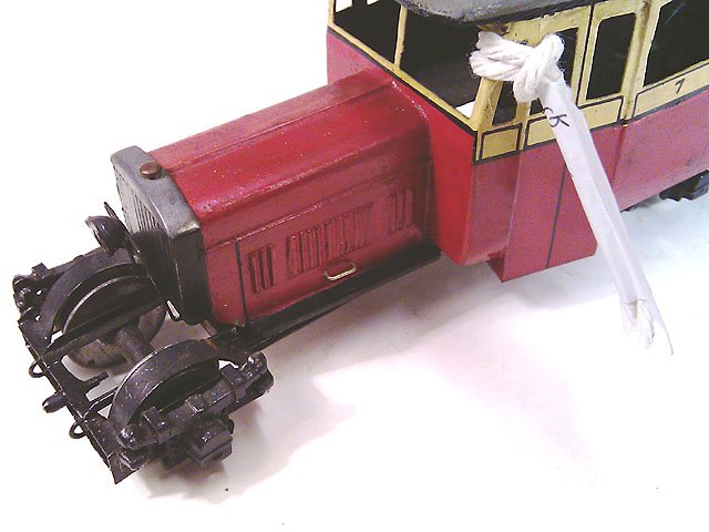
Here are a few photos of Fry's No.7
Eoin.
-
7
-
 1
1
-
-
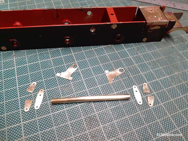
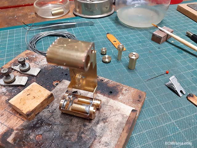
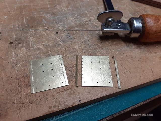
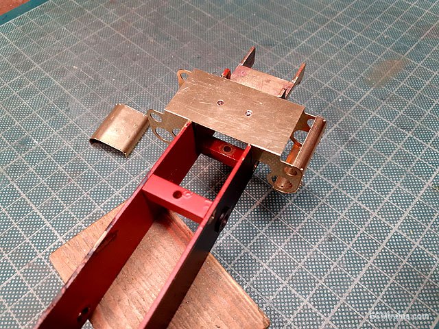
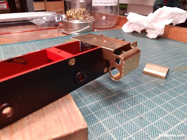
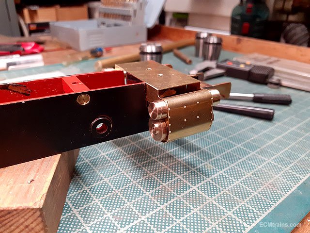
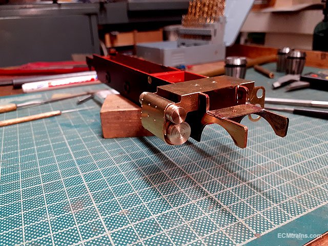
Assembling the cylinders and the motion bracket/plate;-
These are the bits for the motion bracket, a 4mm dia brass cross bar will hold the plates, the chassis has been drilled to take the bar.
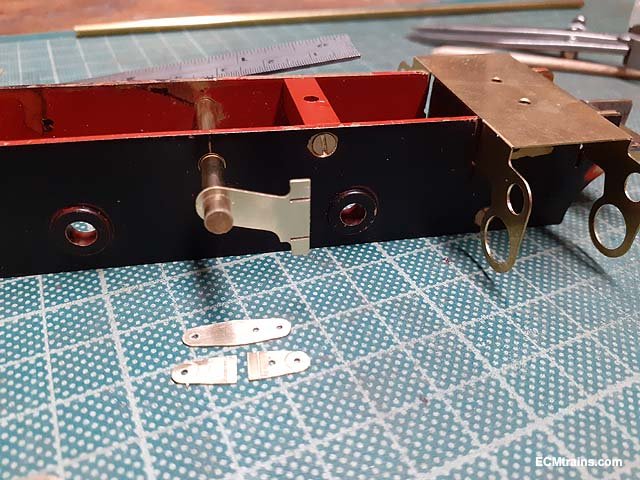
Cross bar threaded through the chassis with the plate to hold the crosshead slide bars test fitted, the fittings below make up the motion hanger plate which will be soldered onto the ends of the crossbar.
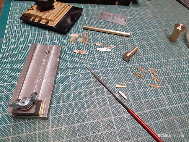
Filling up the fold line on the steam valve slide bars, the bits are held in a 'Finger Plate' made up many moons ago from mild steel- a very handy tool for holding little bits.
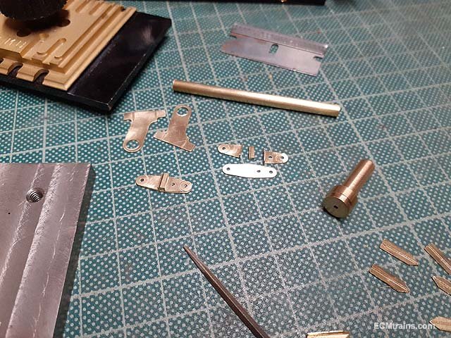
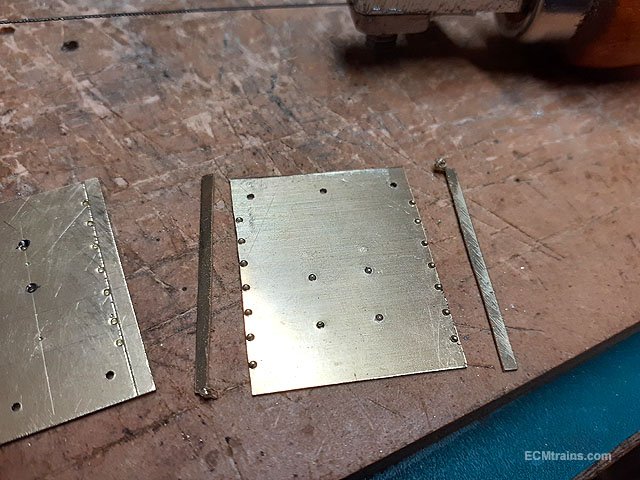
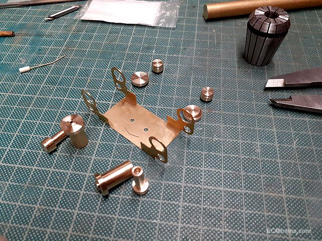
The bits for the motion brackets are folded and prepared for soldering.
The plates are pre-thinned with solder and then sweated together in the clamps.
Done and needing a bit of a clean up.
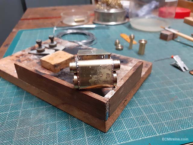
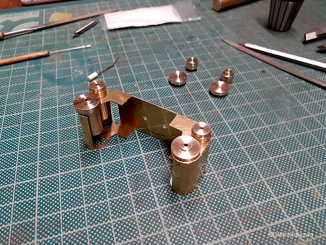
The cylinder wrapper being soldered on the cylinder frame from the inside.
One on and other one to go.
Then the cylinder turnings are soldered in.
Complete.
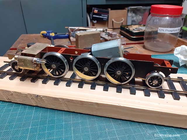
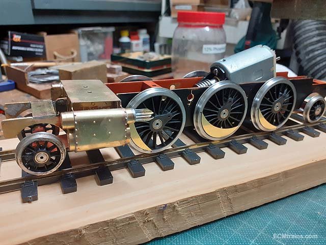
The steam cylinder crosshead guides were soldered on, they were held in place with an aluminum jig while soldering in place. And the wheel weights have been installed with epoxy.
I had another computer failure and lost a few photos of that process!!
More later......
Eoin.
-
3
-
-
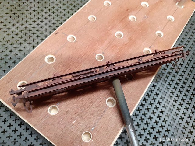
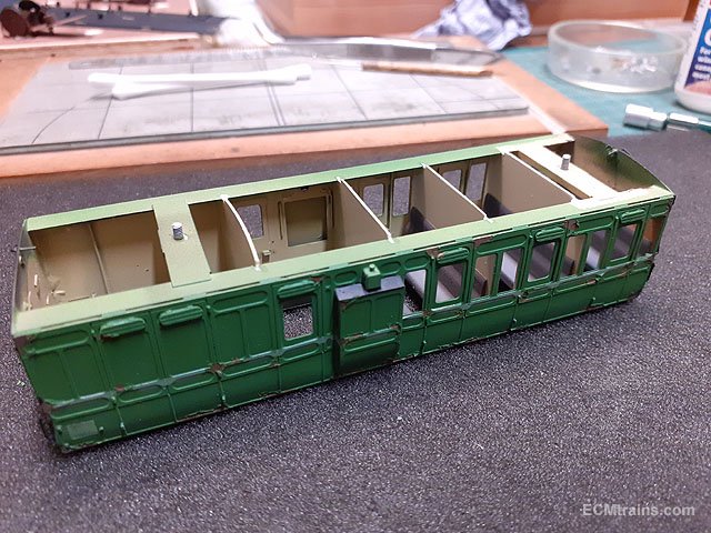
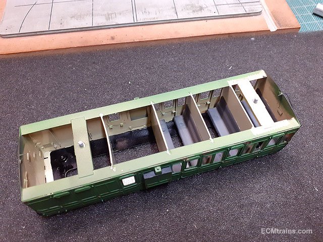
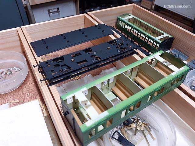
Another project back on the workbench after a modelling brake looking after family and the house;-
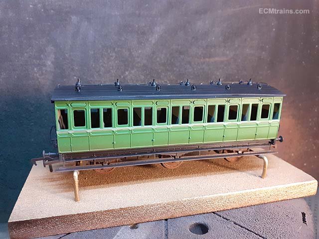
First layer of weathering added to the chassis, this coach is the heavy weathered one, the other three will be lightly done.
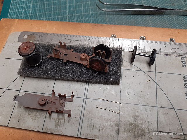
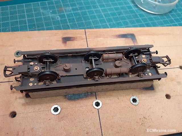
Wheels on, the wheel sets are held in place by a .5mm brass wire epoxied on.
Partitions and seats installed.
Roof gas supply pipe installed.
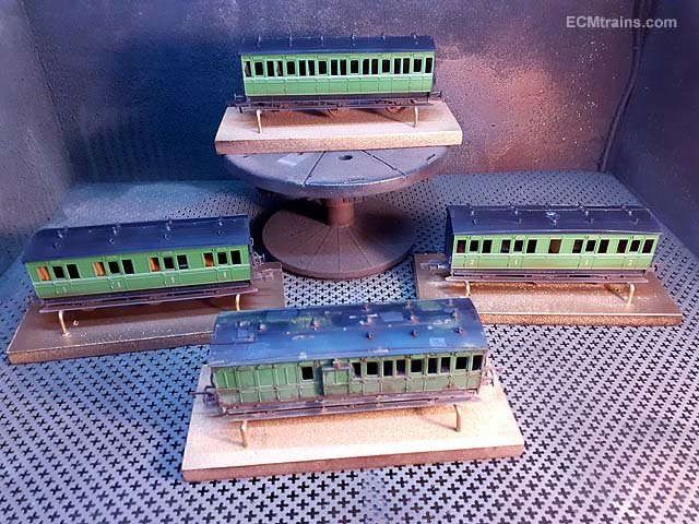
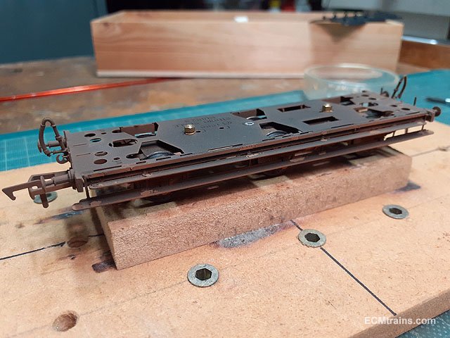
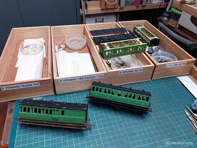
The four coaches are now ready for final weathering and lacquering, then the windows and door handles will be installed........
Nearly complete!!
Eoin.
-
8
-
6
-
-
A tip for running Mamods;-
Do not run it for any longer than 1 or 2 fuel tabs! The water level sight glass in the backhead is only plastic, if the water level gets two low the heat in the boiler melts the plastic, with water n steam gushing out. It's not violent but that's the end of the sight glass, spares are available.
But knowing this and keeping an eye on the water level, not running it for more than 2 fuel tabs, this can be avoided.
Eoin
-
2
-
1
-
 1
1
-
-
@Broithe yes I had a similar situation once, the hinges had a removable pivot pins, on one of the hinges the pin could be pulled out by ones fingers.
A lot of old style aluminium windows are easy to get through- the section that holds the glass in was on the outside, after pulling out the rubber seal there was enough play to pop this alu section off and then the glass could be removed......
Eoin
-
1
-
1
-
-
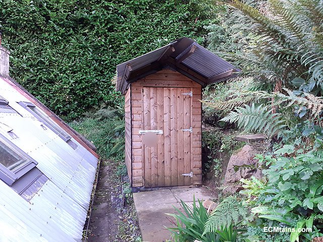
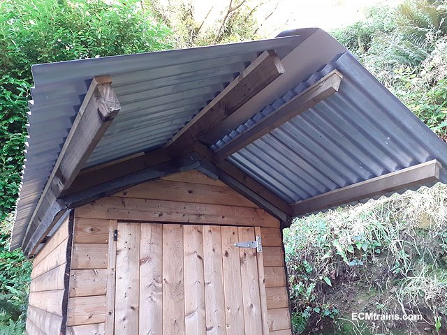
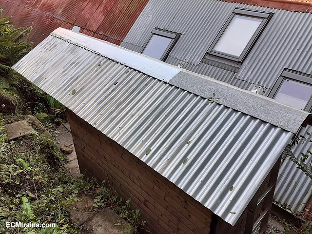
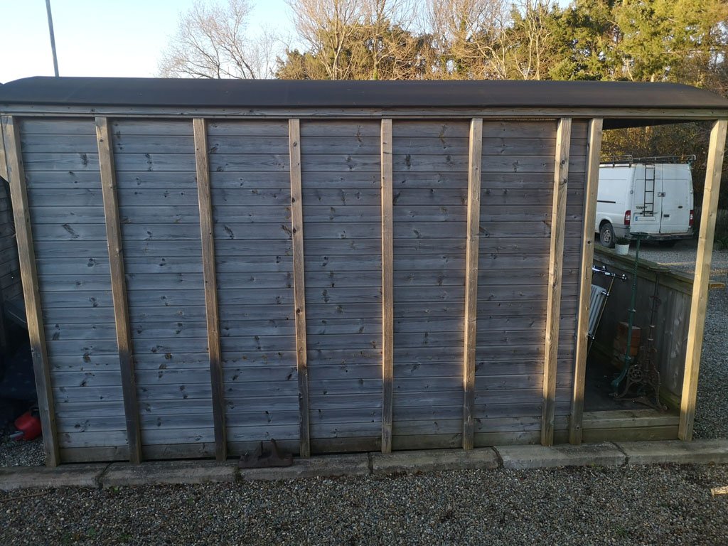
I eventually got the insulation and corrugated sheeting on the roof of the 'Shelving Shed';-
The roof was extended out to give a bit of porch cover to the door for those rainy days. The locking and hinge system was also upgraded for better security.
The timber purlins were fixed down on top of the existing tar roof finish, 80mm thick styrene insulation was installed again on top of the tar sheeting, then the corrugated sheets. Timber barges and eaves are next, there will also be metal barge pressings when the timbers are done.
More later......
Eoin
-
4
-
-
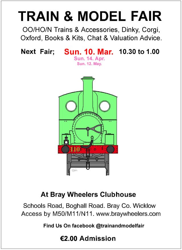
The March Fair Date;-
-
2
-
-
@David Holman Check out 'Ghost' printers online, these are setup to print white. Fine for white only. The problem is if you want to print colour on a white background the sheet has to go through the printer again- which causes problems with registration ie;- lining up! Your talking £600 - £800 for the printer.
Loads of videos on youtube- type in 'ghost Printers'
One can print inkjet/laser on white decal paper, but the decal has to be cut out by hand. Printing inkjet on transparent sheet is useless the model colour bleeds through the inks, laser is slightly better!
Eoin
-
2
-
1
-
-
I have 3 cats that hang in the garden, their not mine, but all the neighbours think they are!
I don't allow them in the sheds, they do try, last time one got in the squirt smell lasted for weeks!!
Eoin
-
2
-
-
February Fair Date;-
-
2
-
-
It would seem that the link above is not available to the public anymore!
But this popped up in youyube;-
Eoin.
-
3
-
-
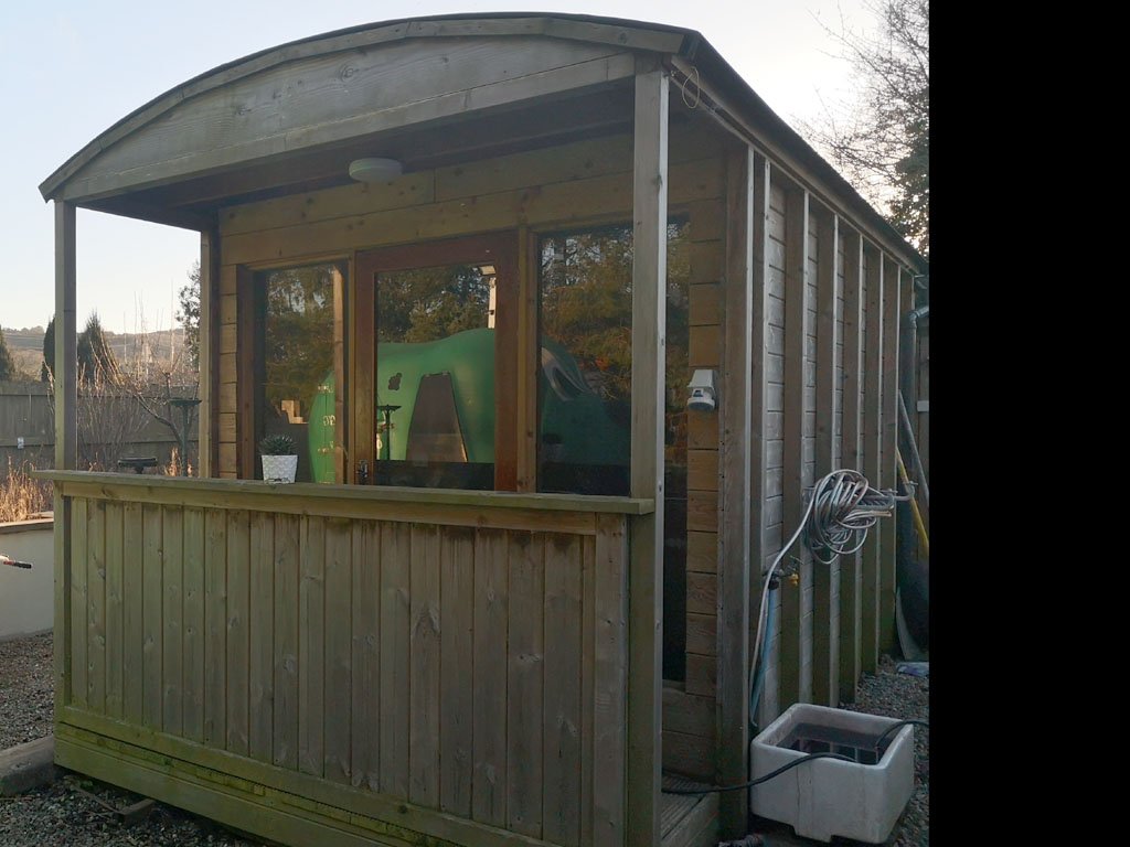
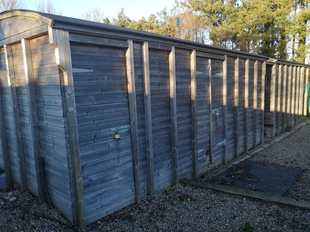
@Gabhal Luimnigh Here are a few photos of the sheds I mentioned above, I know it's different to what you have in mind but it gives some ideas, especially the ground level detail;-
Eoin.
-
3
-
1
-
1
-
-
Check out the resources on here for dimensional ideas;- https://irishrailwaymodeller.com/resources/proto_drawings/
Eoin
-
1
-
-
@Gabhal Luimnigh Not sure about the availability of the IRRS drawings- Anthony McD' looked after the drawings but sadly he passed away a few years back, though contacting them will answer the question of availability?
Line drawings with principal dimensions can be found in Ian Allan's publications like;-
'Narrow Gauge Rolling Stock' by Desmond Coakham.
'The County Donegal Railways Companion' by Roger Crombleholme.
I know they are a different gauge but a great starting point, also I sure more published drawing recommendations can be offered on here!
I also know a man who built 2 storage sheds in wagon fashion, if he is agreeable I could get a few photos of what he did if you like?
Eoin
-
1
-
-
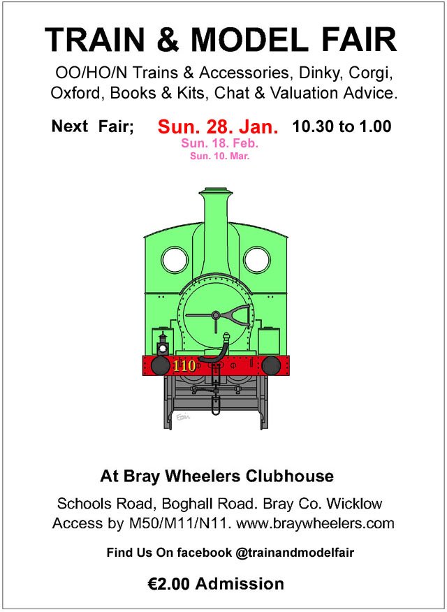
The first 2024 fair date;-
This years flyer is sporting 'Bat'
Happy New Year
Eoin
-
4
-
-
@LNERW1 I for one, would be delighted if you post up photos of the locos & stock.......
Eoin
-
2
-
2
-
-
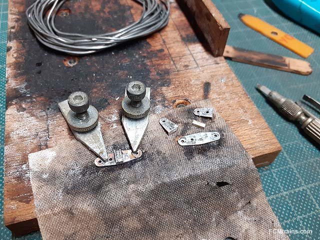
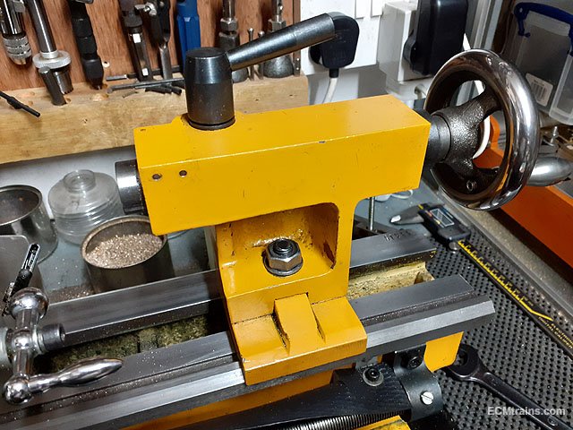
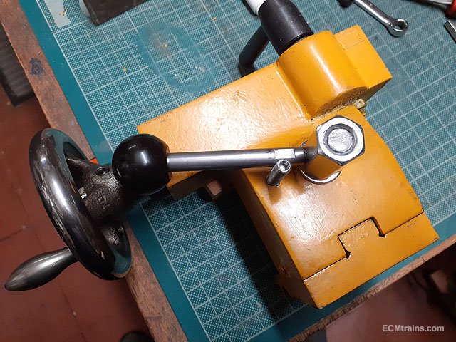
Modifying the Clarke Mini Lathe Tailstock;-
The standard Mini Lathe tailstock comes with a basic system to clamp it down to the lathe bed- a nut n bolt requiring a spanner to operate! There are options when purchasing the lathe, one is a lever-cam tailstock clamp, but Clarke do not have this option. Others do, also kits to convert are available on-line.
The use of a spanner every time to clamp & unclamp is a pain- lever action would be much better.
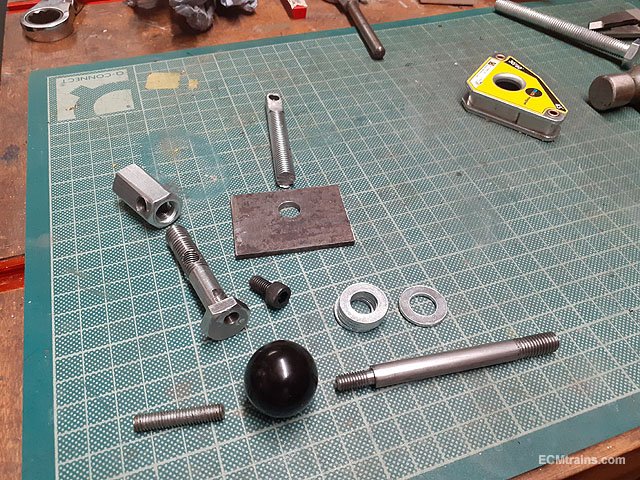
I found a chap on Youtube who did the conversion with;- M10 threaded bar, M10 bolt, M10 coupler nut, M6 capscrew, 4mm MS plate, and a length of 8mm dia MS bar for the lever handle.
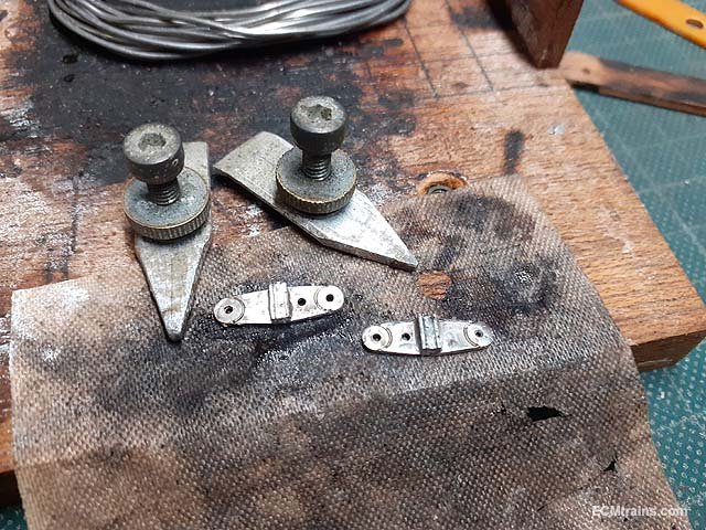
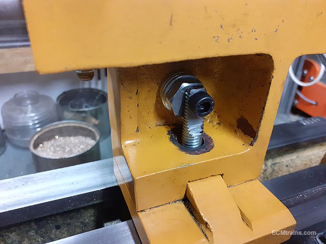
The existing tailstock clamp setup.
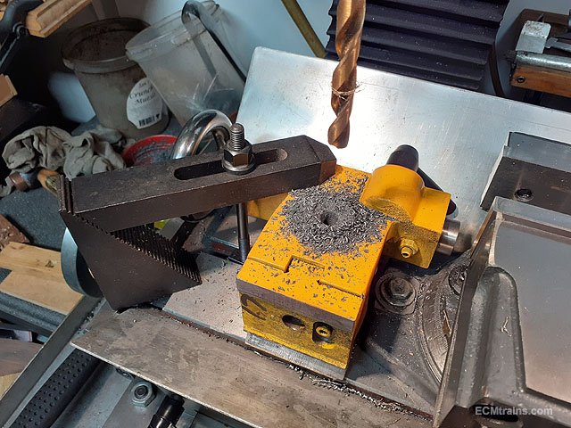
Drilling the 10mm dia hole for the cam bolt to pass through to the rear of the stock where the lever will be fixed.
All the bits, the cam bolt has the M6 capscrew threaded in its head 3mm off centre to create the cam, the coupler nut holds the cam bolt in the stock body which is cross drilled and tapped M8 to take the operating handle.....
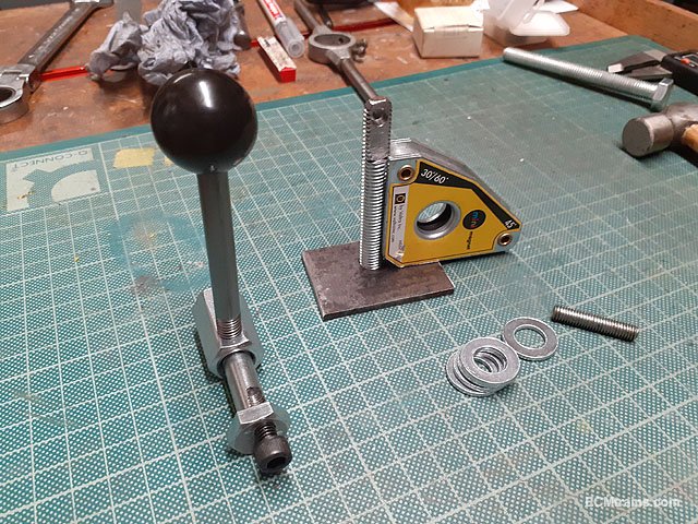
........like this. The clamp plate and the M10 modified threaded pull bar needs a weld on the underside. This pull bar is cut to size so that the cam rotates anticlockwise from 4 o'clock up to 1 o'clock where the mechanism locks, thus locking the tailstock to the lathe bed. The washers are used to pack the clamp bolt in the stock to line up with the pull bar.
The cam arrangement with the M6 capscrew and washers fitted.
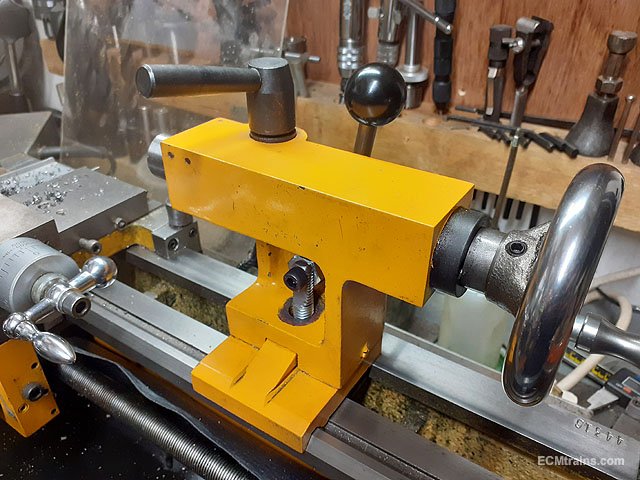
A M6 grub screw was drilled and tapped into the stock body to hold the handle in easy reach when the tailstock is unclamped. Flats were milled on the lever handle for a 7mm spanner to tighten it up.
Up and running, it works beautifully, holding the tailstock rock solid.
I wont need that spanner any more.
Eoin
-
6
-
-
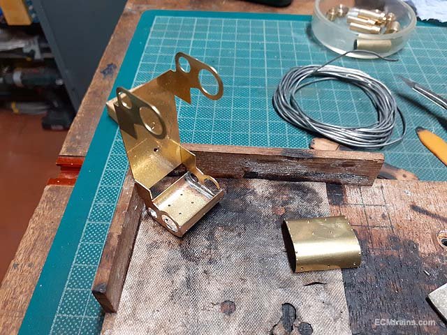
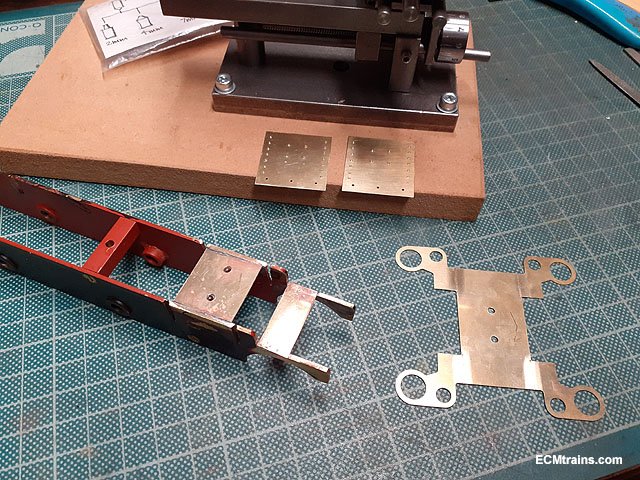
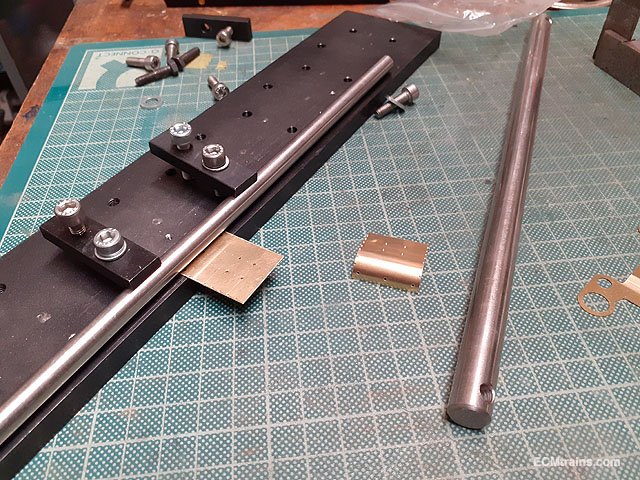
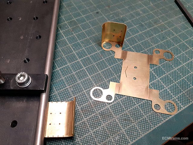
Time to make up the cylinder parts.
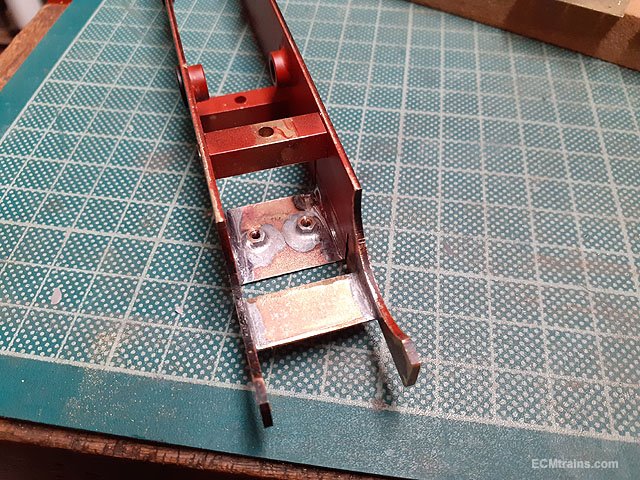
A stretcher plate was made up and soldered between the frames to mount the cylinders on the chassis and the cylinder covers had their rivets popped.
Two 8BA nuts are soldered to the underside of the stretcher plate for fixing the cylinder assembly.
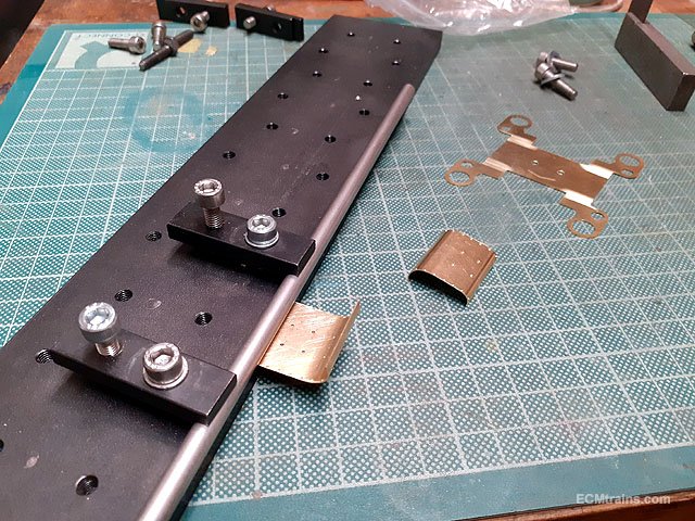
The cylinder covers had extra meat on the sides so that the sheets would not distort during the riveting process, this extra was cut off using a piercing saw.
A bit of cleaning up required but the rivets are right on the edge with no distortion.
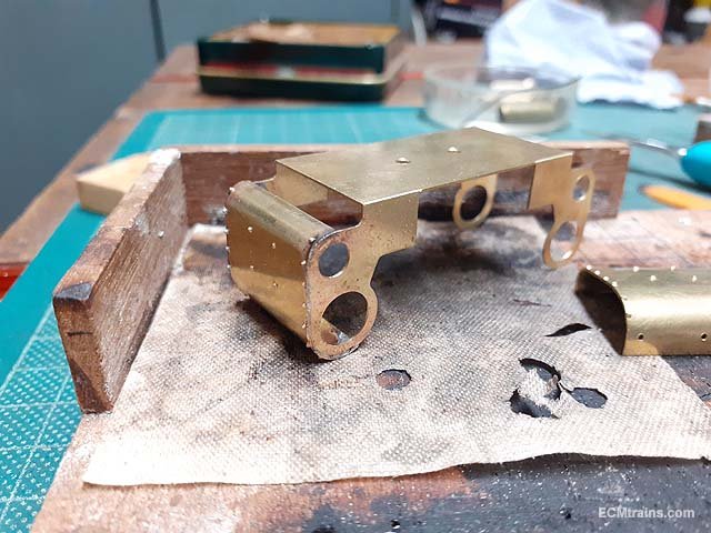
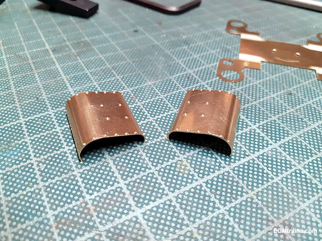
A bit of bending
Done.
The cylinder frame was folded up and the covers are adjusted to fit.
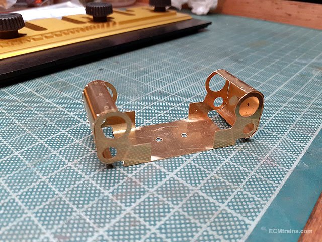
Having a look
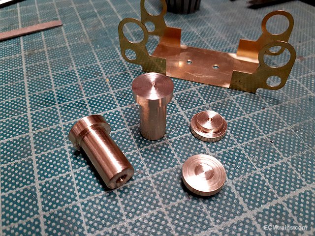
Next was the cylinder parts, turned up on the lathe.
The full bunch, complete and ready to test fit.
A bit of broaching was required but everything works!
A few more bits to process and then the lot can be soldered up.......
Eoin.
-
6
-
3
-
-
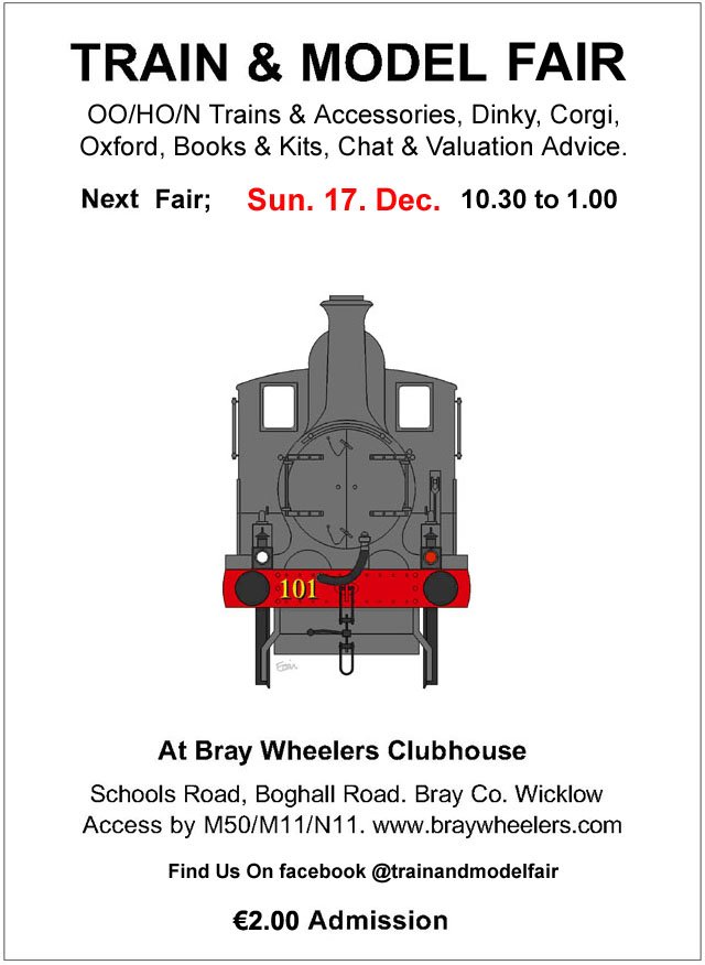
December Fair Date;-
-
4
-

GSWR/GSR/CIE Six-Wheeled Coaches - ECMbuild in Gauge OO
in ECM Model Trains
Posted
These coaches are now complete;-
Brake 3rd.
All 1st.
All 3rd.
1st & 2nd Compo - Lav.
The End.
Eoin.