Irish Mark
-
Posts
5 -
Joined
-
Last visited
Irish Mark's Achievements
")


-
Wow — what great feedback! It’s also a great reminder of how important it is to have good reference sources — and pictures, if possible — when modelling a specific period. Here are a few of my observations from the images (though I’m not sure I’d call them firm conclusions just yet): The biggest distinction seems to come down to the type of lighting in use — with oil lamps appearing in earlier carriages and carbide/acetylene systems coming along later. In the earliest roof detail image, it looks like many (if not all) of the visible features are probably related to oil lamps, likely of the “pot lamp” variety. Interestingly, there are none of the prominent torpedo vents that show up clearly in photos of later-era carriages. It might be that ventilation in the clerestory relied purely on the hinged flaps along its length, which are quite noticeable in the photos. By contrast, most of the images from later periods show acetylene lighting gear and the familiar torpedo-style vents on the clerestory. You can spot an acetylene generator on one end verandah, with pipework running to a chimney-like fitting — possibly an accumulator and regulator — mounted on the roof near the end of the clerestory. From there, pipes lead to the lamps inside. There seems to be just one of those chimney-like fittings per carriage, which would suggest one generator per carriage as well. Who would have thought that such a small detail could be so fascinating? A big thank you to everyone who’s shared their knowledge and insights!
-
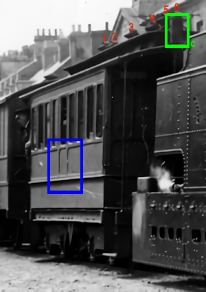
Wonderful feedback. Thanks. I have most of the books Mol_PMB referenced and looked back through them with the benefit of those insights. I do not have the “Lost Railways of Co. Tyrone and Co. Fermanagh, Johnson” book. I did find a low resolution front cover image and can make out the details noted. A higher resolution scan of that image would be a useful addition to my collection if that’s not too much trouble – thanks in advance. I had not picked up the vents/lamps distinction provided in the “p.71, dated 1910” notes. That’s very valuable. The Flickr image is not one I’d seen before and has good detail and contrast. It makes the single middle side panel very clear (the direction I went, so that’s pleasing) and the 6 unevenly spaced vents and a chimney are obvious if not totally clear (my argument for this quick build is that the venting was rationalized in a later refit – I’ll make up for this liberty with a more correct representation when I build my 3mm/ft scale stock later). I’ve cropped that image and picked out those details below. Any idea about the chimney detail such as were it vents from – presumably it must be connected to the clerestory somehow?

-
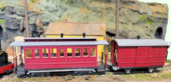
Here’s where I’m at with my CVR All-1st and the accompanying Goods Van. Both still need a bit of cleanup, decals (I haven’t decided what to do there yet), and weathering to finish them off. The only detail I’m still unsure about is the width of the center panel below the windows on the coach. I went with a panel that’s one window wide, lined up with the middle window of the nine on each side. It looks a bit narrow, especially since on the longer coaches this panel was two windows wide, centered on the middle pair of twelve windows per side. I’m not planning to change this build, but if anyone has more accurate info or a better interpretation, I’d love to hear it so I can make adjustments on future models. The rolling stock is set up on the 4mm/ft 9mm gauge OO9 18in x 12in “Bosca Scarp” micro layout which I scratch-built (apart from the loco and two tunnel portals) in just two weeks for a recent regional NMRA convention. With that short timeframe, I decided to build two “prototype-style” carriages using old Egger-Bahn chassis for the event—and that turned out to be a good call. Still, I always knew I’d want something closer to the prototype, especially since the micro will be used as a display piece at club shows. That’s what led to these “upgraded” versions. I’m pretty happy with how they’ve turned out as quick, “layout-quality” builds. I’ll eventually do more detailed 3mm/ft scale (my preferred scale) 9mm gauge versions—but don’t hold your breath for those!
-
Thanks for the input. I’m planning to go with a three-vent setup for now. The images I’ve looked at do show something a bit unusual with the vents on the All-First carriages, but in the absence of any solid evidence to the contrary, I’m comfortable assuming the three-vent configuration was part of the rationalization process—based on established practice and experience with the longer carriages—when First Class was phased out. Feels like one for the “life’s too short” list! That said, if clear evidence of a retrofit ever turns up, swapping out a roof detail wouldn’t be a big deal. Pictures to follow in due course.
-
Hey all, Sorry if this is a bit of a beginner question or something that’s been asked before — I’ve had a look around but haven’t found a clear answer, so here goes. I’m trying to figure out how many torpedo vents were on the all-first coaches of the Clogher Valley Railway, and how they were spaced. The best photos I’ve come across are on pages 33, 89, and 151 of the Patterson edition of The Clogher Valley Railway. From what I can tell, it looks like there are five or maybe six vents — which is more than the all-thirds and the first/third composites (it seem to be weldocumented those had just three). Also, there seems to be an extra one mounted on a rectangular plinth above the balcony at one end — maybe even both ends? Would love to hear any thoughts or insights if anyone has looked into this before. Thanks!