

Admin
-
Posts
124 -
Joined
-
Last visited
Content Type
Profiles
Forums
Resource Library
Events
Gallery
Blogs
Store
Community Map
Posts posted by Admin
-
-
And coverage of the approach to move it back to Malahide:
Still some efforts to get it to go that way - http://www.fingal-independent.ie/news/committee-to-approach-bus-eireann-3040208.html
-
Listen to the podcast/,p3 from the Live Line Programme which discussed:
http://www.rte.ie/podcasts/2012/pc/pod-v-08031216m39slivelinerailway-pid0-999744.mp3
-
-

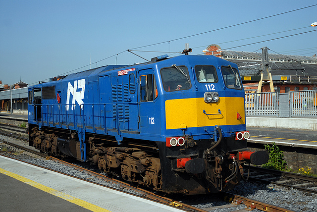
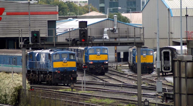
from Railway Pictures website
-
With the Murphy Models 071 model just around the corner - discuss here!
-
[h=1]Adjustment to the yards[/h] April 2, 2012 | Layout Build
After seeing everything down, the yard area of the terminus is being tweaked slightly.
The Ballast area has been lengthened to 4.5 feet with two small sidings for tampers / per way equipment to stable. The long siding can then be used for ballast hoppers / autoballasters to be filled by digger.
The depot has also been ‘rationalised’ with a simplified track plan, single road running shed and washplant added anda depot crane added to the bottom siding.
The changes mean a ‘proper’ looking 12-15cm gap between the depot lines and the mainline at bottom…
-
With a little help from some Thomas engines and two little engineers
Probably too much clutter above….
Carriage sidings…
The centre three roads are the freight sidings….
Looking back into the depot (the two lines on the right are the mainline)
Behind the depot, a small row of Georgian terraces and a derelict factory
Peco depot shed anyone?
Looking across the freight sidings towards the carriage sheds..
Slightly aerial view
Ignore the rolling stock
The reason for a TGV, Gordon, James and Virgin mk3′s sharing the layout
-
.. and the freight and ballast/per way sidings get cut and joined and pinned down to verify clearances.
-
To get a little break from wiring, finding shorts and to also try and resist the temptation to ‘play trains’ on the terminus section, I decided to ‘mock up’ the track on boards 3 and 4.
On this side (from rear to front) there will be three Coach sidings / train storage, a 2 road ballast bank / per way storage siding, a three road freight terminus as well as a small depot.
-
It’ aliiive!
It might not look much, but those lit LED’s are very exciting
Here are two videos I took to prove it’s now actually live!
8208 Takes a spin…
And Veissmann’s new P&T Tamper tries to tamp imaginary ballast
-
Power bus now done for the terminus district.
-
Having gotten a feel for how long jobs are likely to take now, I thought I would set out the roadmap of what I hope to cover / achieve in the next 6-8 weeks.
- Complete the Main power bus for the Terminus District
- Installation of a DPDT (Double Pole, Double throw) Switch and Programming Track connector, which will isolate the front siding of the running shed sidings and allow me to switch between running track and programming track (so I can drive a loco onto the track, switch, and programme / work on it, then switch back and drive it out )
- Installation of 14 Cobalt slow action motors, controlled by Cobalt Motor decoders on a dedicated Accessory Bus (again zoned into a district for the terminus) and correctly power routing all the frogs (the double and single slips will probably warrant entire posts on their own!)
- Installation of Lighting around the running shed. I have some surface mount LED strips which I plan to use to light the Peco pit, and the shed itself, as well as adding a small tower light out front of the shed.
- Installation of Peco concrete platform edging, clearance tests (again) and platform creation.
- Concrete hard-standing at running shed.
Once the above is complete, and assuming I can resist playing trains at that point too much, the plan is to lay the mainline on these boards and commence the mainline ‘district’ power bus, before moving to starting on boards 3 and 4, which are home to the carriage sidings, ballast bank, freight terminal and motive depot.
Longer term plans include Signalling, Occupancy detection and computer control / automation of routes… watch this space!
Any questions, please comment!
-
Still probably another days work on boards 1 and 2 just for the power droppers.
Then on to the frogs and motors.
Once I have all the power droppers in I should be able to do some limited testing with a loco.,.
-
Just need to wire it all up now!
-
Have a nice forest of droppers growing under the board and am powering the points directly now for ideal running.
-
I’m about half way through all the droppers for boards 1 and 2 and the point adjustments and pre-drilling for cobalts…..
At least my soldering is improving slightly with practice!
-
45 Droppers cut to length, and some initial soldering tests!
I am also soldering the Proses Buffer stops to the adjacent rails, to ensure a good connection, and have started breaking some peco points!
-
Here is a step-by-step guide for installing an inspection pit under the running shed.
First, the pit is glued together as per peco instructions, and then measured up in place. The Woodland Scenics foam is cut away with a blade and the four corners drilled out with an 8mm wood bit to make room for the jigsaw.
Next, cut the slot with the jigsaw (observing safety
)Once done, pop the pit in an ensure a good fit. You might need to trim or file a bit here.
Next, remove the web from the back of the track for this section, just cut the web and you can pop the ties off the track for this length, and then slide the remaining web/ties off the track – you’ll need to keep it to re-thread onto the rails in a bit.
Now, carefully thread the rail onto the pit, feeding it all the way through, and then thread the rail back on to the end piece of tie / web.
And it’s done
Doing it this way also means you maintain good electrical connectivity throughout, leading to less stressful running later on -
The track on boards 1 and 2 is now cut and laid and held in place with tacks.
The plan now is to install a Peco Inspection pit under the running shed, and start soldering droppers to the rail undersides on every single piece of track.
I will then work on the points, removing the springs and perhaps replacing some of the more visible points sleepers with copperclad. More on that soon – here is the latest view:
-
Track is now being cut to size and laid. Black underlay is Woodland Scenics Foam sheet, cut and glued with their ‘Tack Glue’ to the baseboard.
-
A small tweak on the terminus – after seeing the track in place, and getting some sound advice, the platforms were simply going to be far too narrow, relative to their length, so the terminus has been ‘rationalised’ a little to allow for two main platforms to reach 3″ wide.
-
Sizing up the track in place on the boards…
-
Cables for the layout DCC Bus and Droppers
Multicore security cable,2x18awg,PVC152m (the grey cable) – will be used for droppers and connecting accessory decoders to motors, etc.
Eco wire 12awg 65/30 red 600V (and black) – will be the main and accessory bus wires(from Radionics)


Twitter Account
in Site News & Help
Posted
https://twitter.com/#!/irishrailwaymod
Will be used to track announcements and key bits of news (and also if for any reason there is a problem with this server, we'll update twitter to let ye know!)