eigyro
-
Posts
29 -
Joined
-
Last visited
Content Type
Profiles
Forums
Events
Gallery
Blogs
Everything posted by eigyro
-
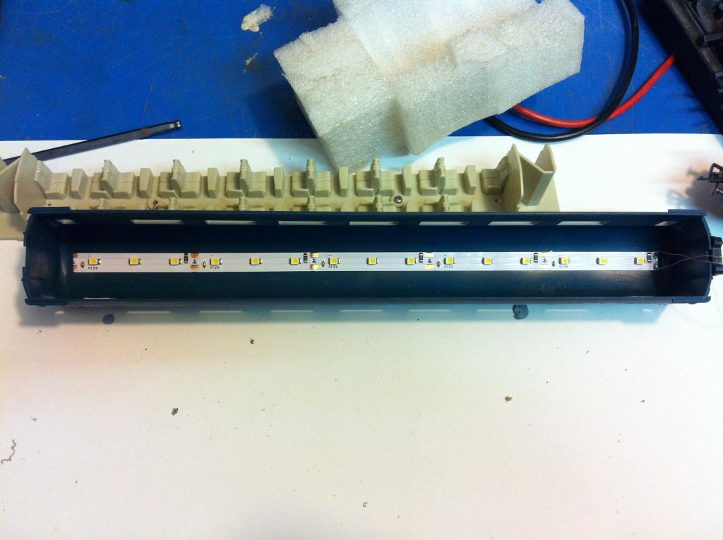
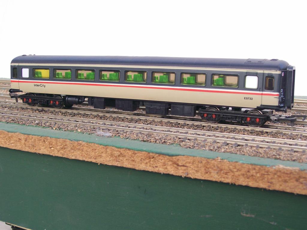
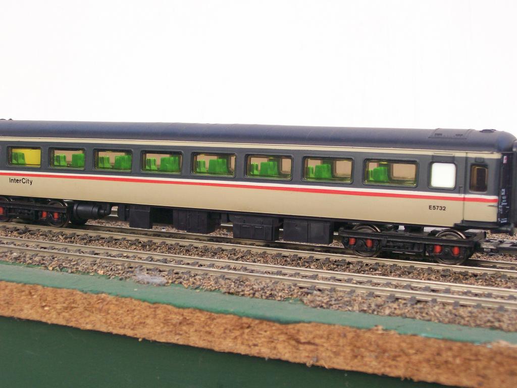
Yes. LED strip. 15 lights per coach.
-
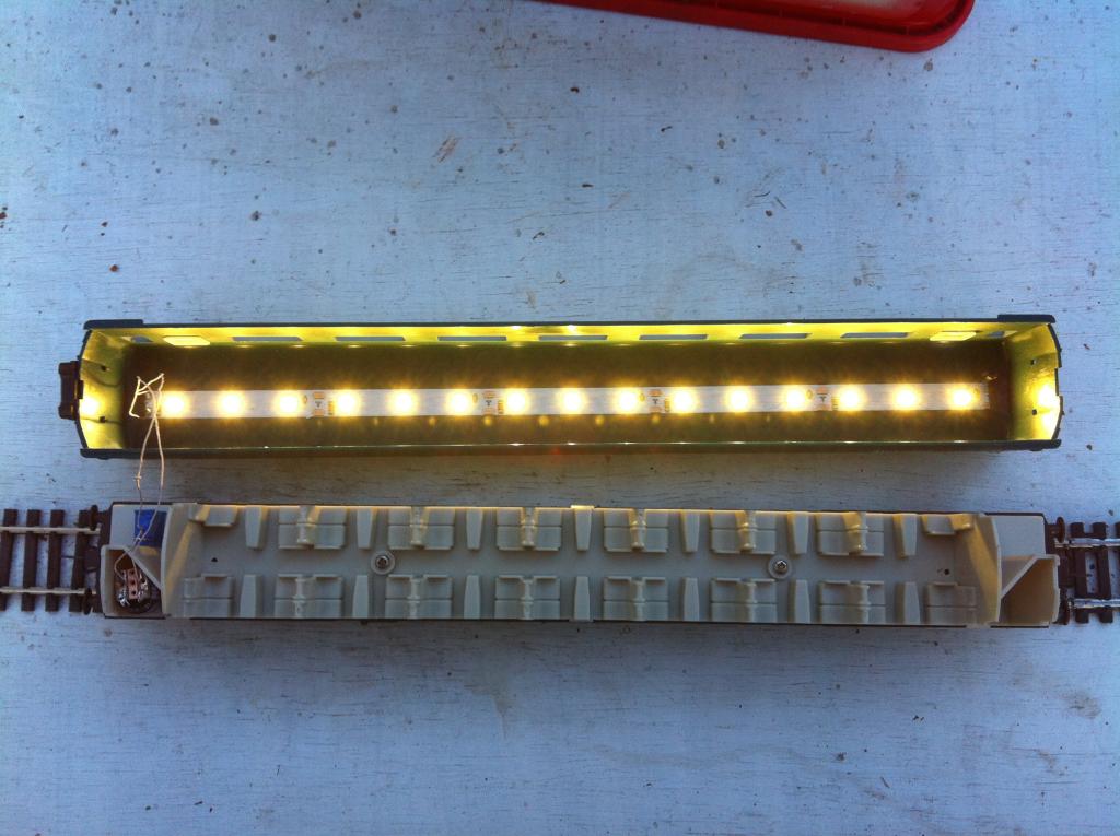
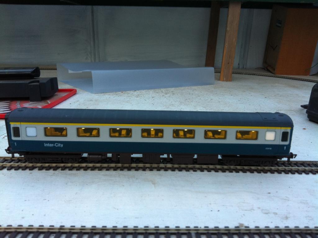
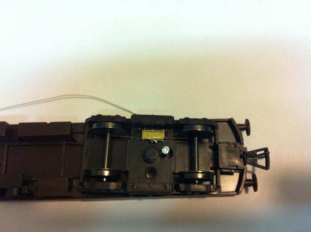
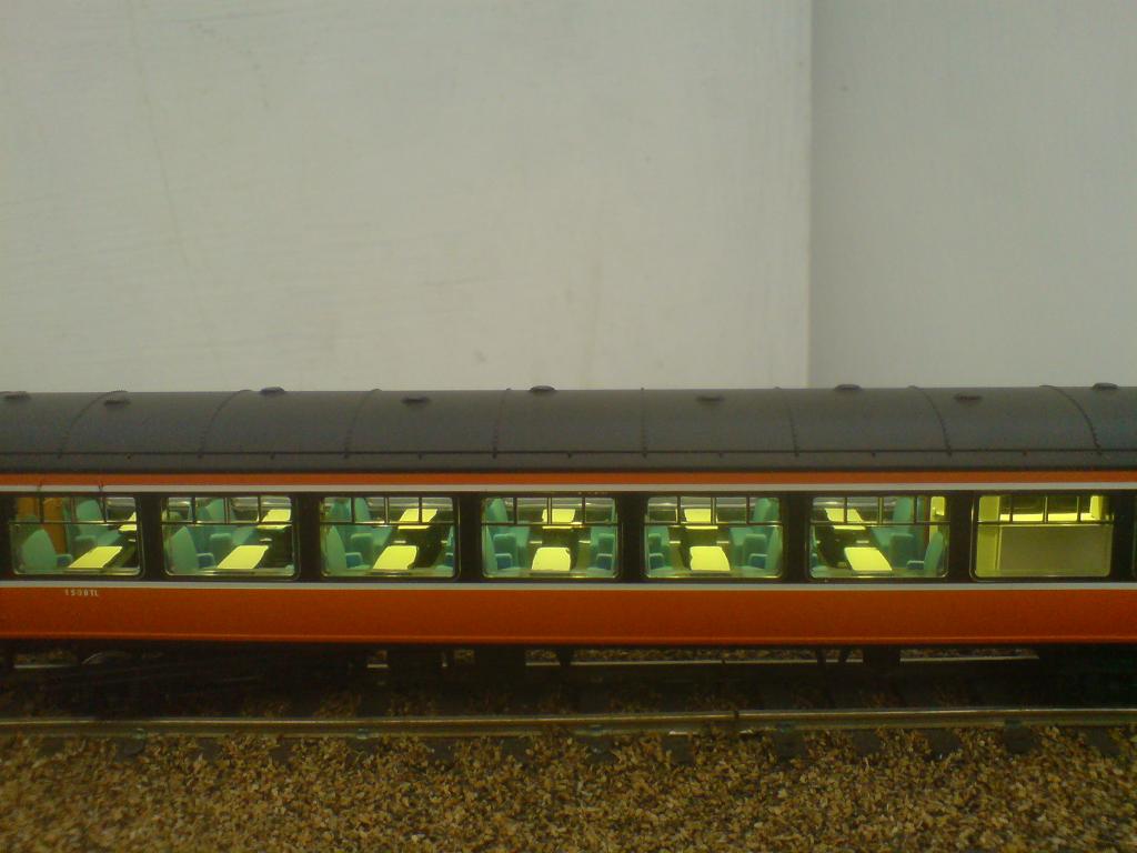
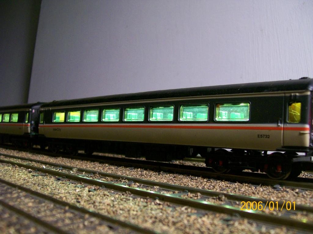
Or, more clearly, I hope, like this; It is a good idea to test the installation at this point, so as to avoid having to pull it apart later. Make sure at least two of the eight wheel contacts are actually touching the inside of their respective wheels. Lay the chassis on the track, with the coach roof to one side. If all is ok, you should see this; I hope these instructions are clear enough. At least they should provide enough information to the builder to decide whether the job is within their skillset or not. Electrically, the worst you can do is cause a short on your track, which DCC systems are well protected against. If you get the LED connections backwards, it just won't light, but you won't damage the LEDs. As with all such projects, you are wearing safety glasses, aren't you.? The kit is part-assembled to prevent polarity issues with the smoother/keep-alive capacitor, and bring it within the skillset of more people. This is what the demonstration sample looks like on track; That's all, folks. Comments are welcomed, good or bad.

-
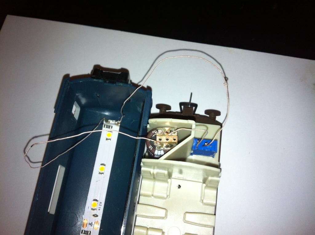
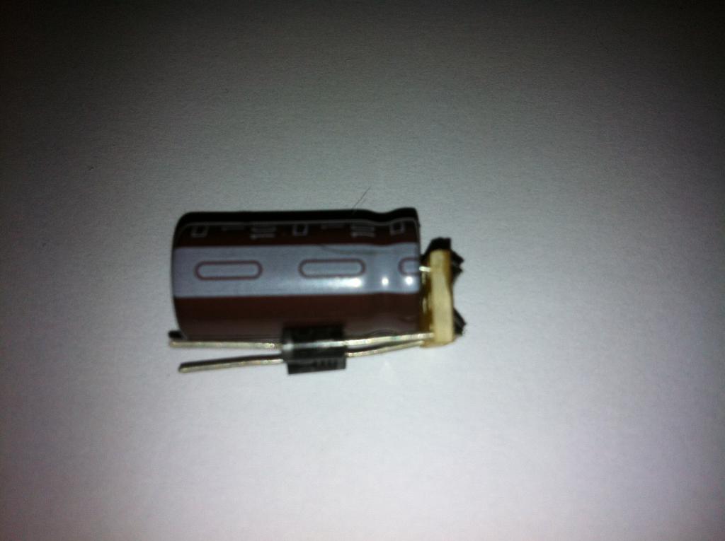
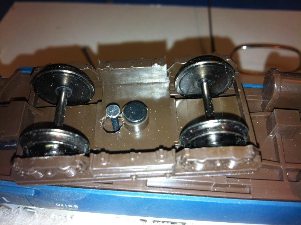
Next, the positive lead from the LED strip, identified by a knot tied in the wire, must be soldered to one connector on the blue pot. It doesn't matter which one. Finally, the small piece of unattached wire, is soldered, one end to the second connector on the blue pot, and the other end to the positive side of the rectifier module. It should look like this;
-
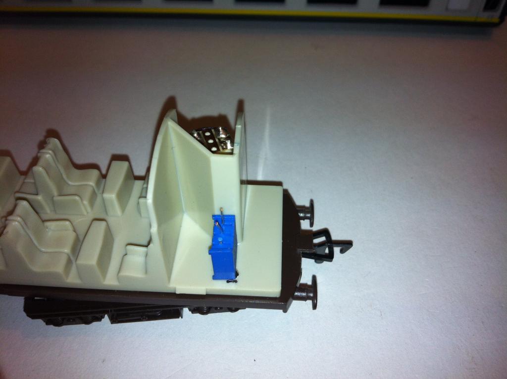
Fit the seat insert back on the chassis. Drill a 3 or 4mm hole through the insert and chassis so the brightness adjuster screw is accessible from underneath using a jeweller's screwdriver. Mount the pot (potentiometer- the blue brightness adjuster) so that the adjuster screw sits in the hole, ideally centrally. Now for the final connections; The negative wire from the LED strip in the coach roof is the one nearest the little black component at the end of the strip. It must be soldered to the negative side of the rectifier module, which can be identified by the broad white strip down the side of the brown tubular component. It should look like this;
-
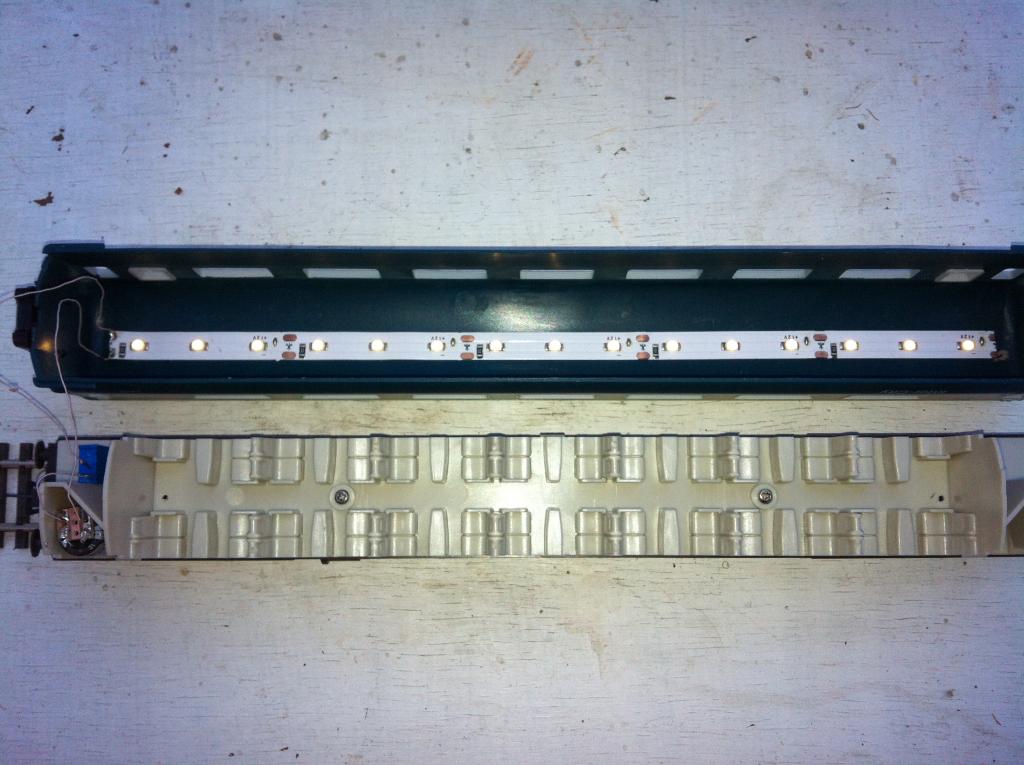
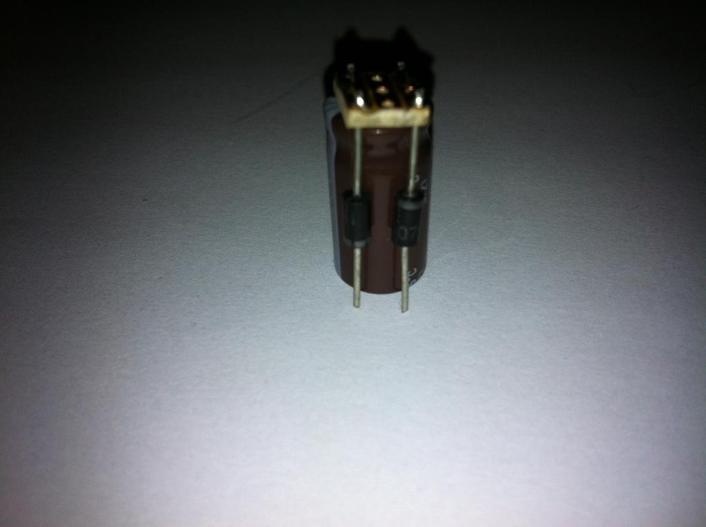
Install the lights in the coach roof. Peel off the protective strip, and fit in place. The adhesive is very forgiving, so don't worry if you have to re-position the strip. See below, and make allowance, if necessary, for bulkheads, toilets etc., in the insert. Drill two wire holes up through the seating insert at the place you wish to site the rectifier module. Don't feed both wires up through a single hole. The holes should be positioned so as to meet the two free ends of the diodes as shown below; Draw the two wire ends up through the holes. Solder one wire to each diode. It doesn't matter which wire to which diode, just try to avoid crossovers. Position the module in place, drawing the slack wire back down through the hole to be coiled neatly underneath, keeping the two coils separate.
-
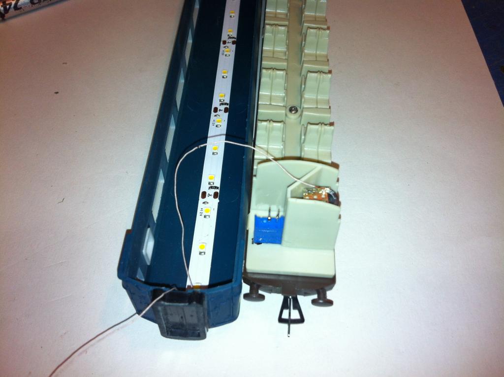
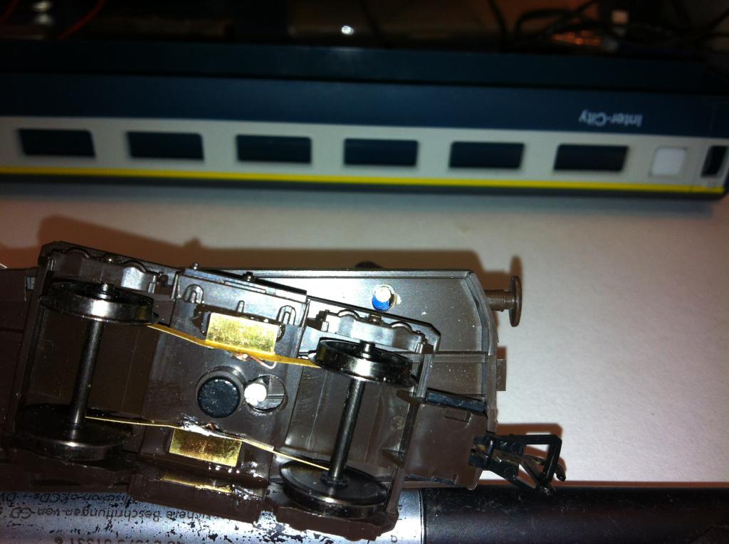
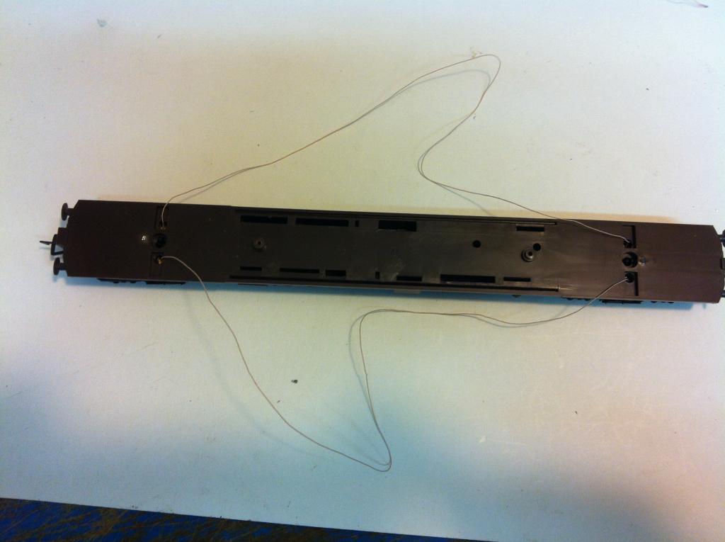
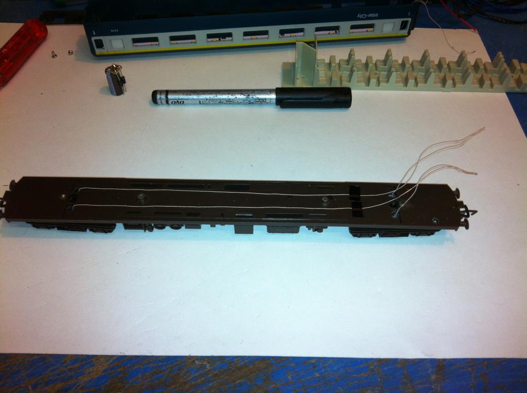
With the wires hooked up and contacts glued in place, it should look like the following photos; Top view; The wires should be gathered as in the next photo; Note the tape holding the wiring gently in place. The loose wire should be gathered and twisted as above. The tip of each gathered end must be 'tinned' with solder. With Litz wire, you should lay the wire on a small piece of wood, place the soldering iron, with some solder on it, on top of the wire end, and 'drag' the wire out from under the iron. This removes the silk insulation and allows the solder to 'take'. That completes the chassis.
-
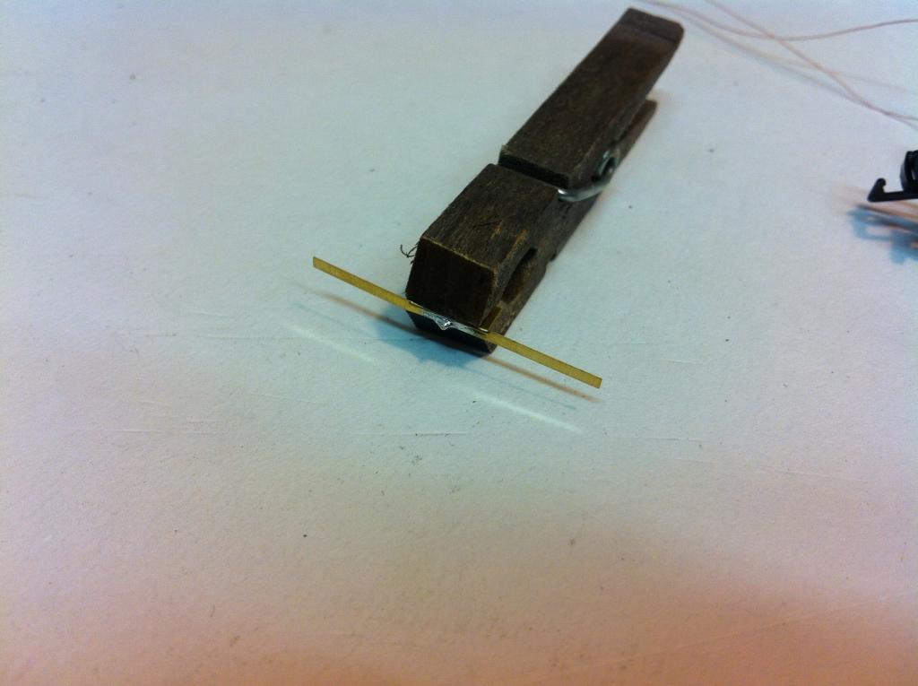
Feed the free end of a pickup wire up through one bogie, along the top of the chassis and down through the corresponding hole at the other end. Glue the attached pickup in place, bending the contacts slightly towards the inner wheel. Below is a suggested method for soldering the free end of the wire to the other contact. This keeps solder from getting under the contact and spoiling the contact patch, which might interfere with the fit onto the bogie.
-
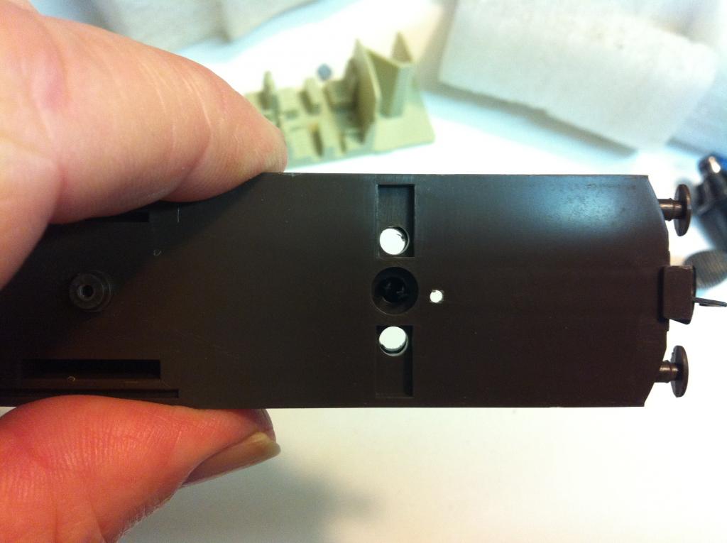
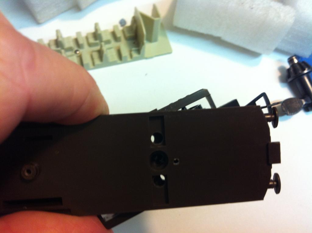
Drill one wire hole each side of the bogie pivot pin, through both the bogie and chassis, for the pickup wires. The holes must be wide enough to allow the passage of the wires without 'scissoring' the wires at the max turn angle. The nearer the hole is to the pivot pin, the smaller it will need to be. See photos;
-
Separate the coach body, seating insert and chassis. You may need to limit the travel of the bogie to prevent it from turning around enough to cross the wires. The insulation on the Litz contact wire is wrapped silk, which allows great flexibility at some cost to durability, so it is advisable to route wiring so as to avoid crossovers, especially where movement/chafing is an issue. The method I use is to drill a small hole through the bogie and chassis, for the limit pin which is fixed in the chassis. Drill a larger hole in the bogie only, concentric with the pin hole. This hole should be made large enough to allow adequate turning radius. See photo below
-
A sample or two; A Craven;
-
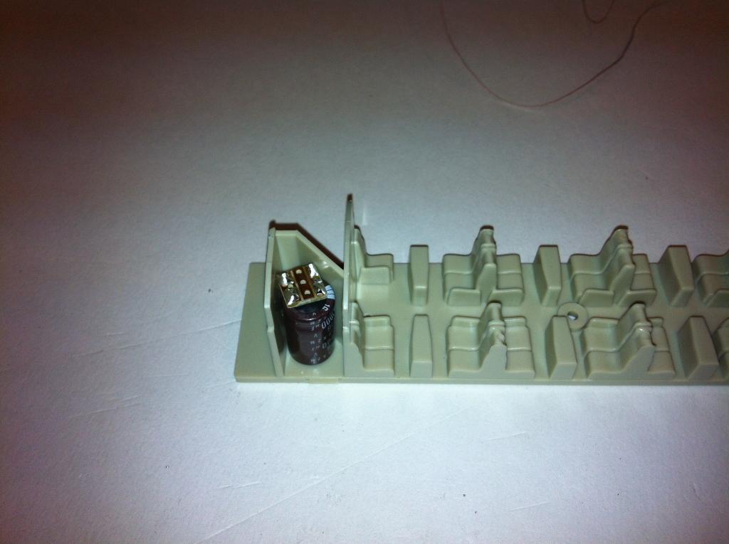
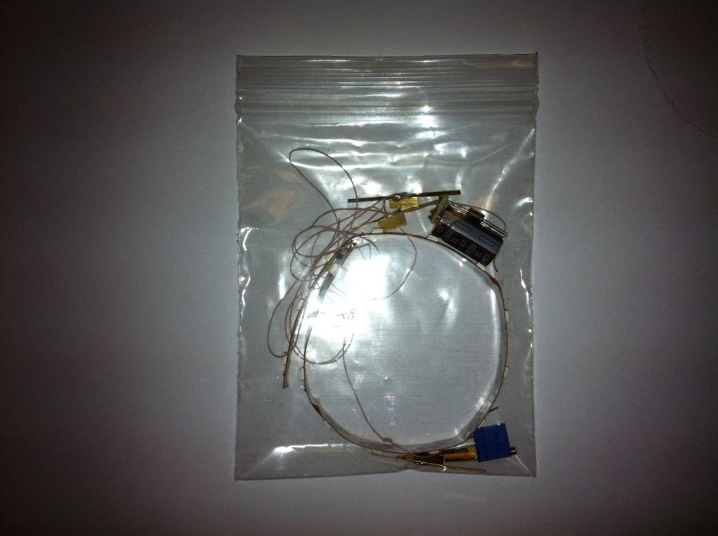
The price is 20 euros + actual postage cost. Currently I have 6 kits in stock. All are pre-tested, i.e. the LED strip and the rectifier module are checked for correct operation. Here is a picture of the packaging. I will try and put the installation instructions on this thread this evening so folks can see the process and figure out if it looks like a runner.
-
-
In case you haven't seen the video on Boskonay's Amiens Street Terminus, here is the link;
-
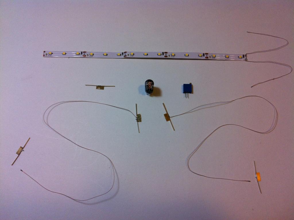
Just a heads-up to anyone who may be interested. I have put together a part-assembled kit for lighting carriages. The kit requires no electrical knowledge other than the ability to solder according to the detailed instructions. It will cost about 20 euros + postage per kit. The kit is identical to that fitted to the D&M De Dietrich Enterprise. I will post the installation instructions with photographs of a typical installation on this thread over the next few days. Watch this space.
-
I have a cunning plan.
-
OOPS! I see its actually a 3-pack. I was so focussed on the kit contents, I didn't read the words. My bad. I don't see any provision for adjusting the brightness. Am I missing something else? Meantime David tells me he'd like keep-alive on the DVT running lights and headlight. I hadn't noticed any problem with that. Thinking hat time. It can be done, of course, but what cost ?.
-
That'd work out about €50 per coach. !!! For that price I'd supply the kit, fit it and paint the insert.
-
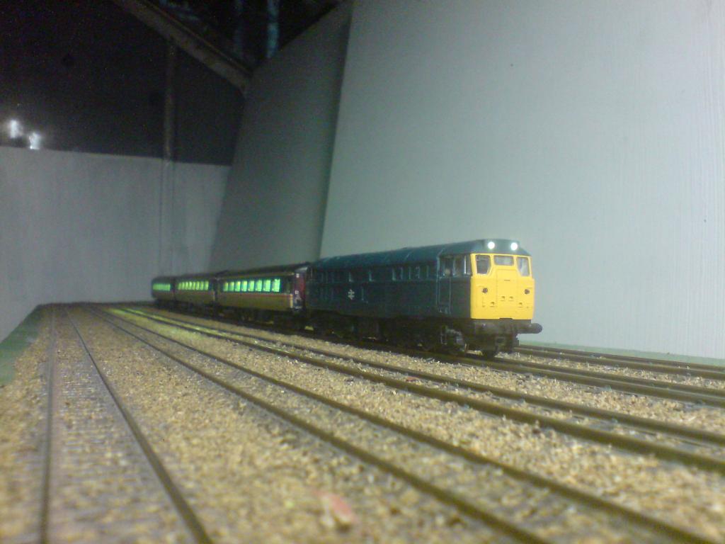
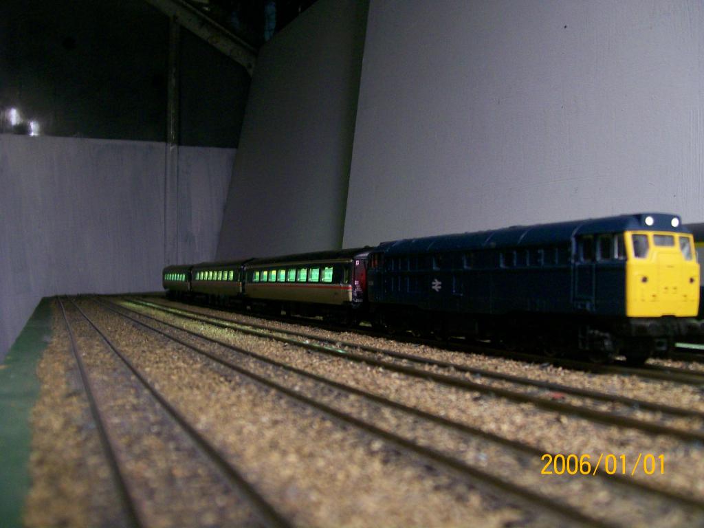
Class 31 with 3 MkII Executives;
-
Close, but this one's my cover story;
-
Having further thoughts about kits. It might be workable. Another thought was to offer retrofits to modellers existing stock. Would there be enough interest, do ye think?
-
More photos;
-
Not NASA, just as a Marine Radio Officer (Sparks) with Marconi from 74 to 79, then a hardware service engineer for Big Blue from 79 to 2010. Now retired.
-
Hi Anthony, I think this may be the one I referred to in the previous post. If I read it correctly it consists of the keepalive unit, some wiring and wheel pickups. I don't see any LEDs included.
-
Good question. I was half expecting to encounter this problem, but I have lit up 10 coaches simultaneously at full brightness with no problems. Tried this with two different DCC controllers, and a Gaugemaster DC controller. (These coaches will work reasonably well on DC as long as the controller has a good short-circuit protection, NOT a thermal cutout, but they are not optimised for DC.) There is a flickerfree kit available on the market which uses a VERY high value capacitor. It would be interesting to know whether they have a problem with long trains. However, I'm not curious enough to buy 10 of them to find out.
-
Hi again, The carriage is lit by a string of 15 LEDs, which require a DC current. The rectifier converts the DCC AC current to DC, but leaves a ripple voltage. The LEDs might dislike the ripple voltage over time, so the capacitor ( think water tank for electricity ) smooths out the ripple. As you no doubt know, the electrical contact between the track and wheels, and between wheels and pickups, is pretty lousy, resulting in flickering. If you use a big enough capacitor (water tank), it can supply the current during the breaks in feed from the track. That, combined with pickups on all wheels, gives a pretty much flicker-free result. The output from the rectifier/smoother is fed through a variable resistor (multi-turn cermet trimmer potentiometer), to the LEDs. The trimmer has a small screw projecting to allow off-track adjustment of the brightness. The photo in the first post was taken in full daylight (not direct sunlight) in the greenhouse where my bench is. The brightness can be adjusted to suit almost any ambient light level from daylight to near darkness. You can see other samples of my system on the D&M de Dietrich photos and videos on the Amiens St and Tara Junction layouts on this forum. I have some other photos of BR MkII coaches, but I'm not sure if the protocol allows me to post these here. Also a Class 31 loco. For the locos or DVTs I use a four-function chip. All the components used are polarity-sensitive, apart from the trimmer, so a kit might not be a good idea. As Anthony says, Electrolytic capacitors dislike wrong polarity and sometimes they make their displeasure known. A considerable amount of work is devoted to eliminating light bleed around the window inserts, which can spoil the effect if not attended to. The wiring assembly is organised so that coaches may still be disassembled (with care). My next project is to attempt fully adjustable running lights and headlights for the de Dietrich DVTs. I am absolutely gobsmacked at the quality of the models and layouts on this site, for which I don't have the talent or patience, unfortunately.