

Sean
-
Posts
890 -
Joined
-
Last visited
-
Days Won
3
Content Type
Profiles
Forums
Events
Gallery
Blogs
Posts posted by Sean
-
-
https://www.thingiverse.com/thing:5028546
a very similar sort of jig is used when making h0f points.
you can also buy peco rails without buying complete track.
-
 1
1
-
-

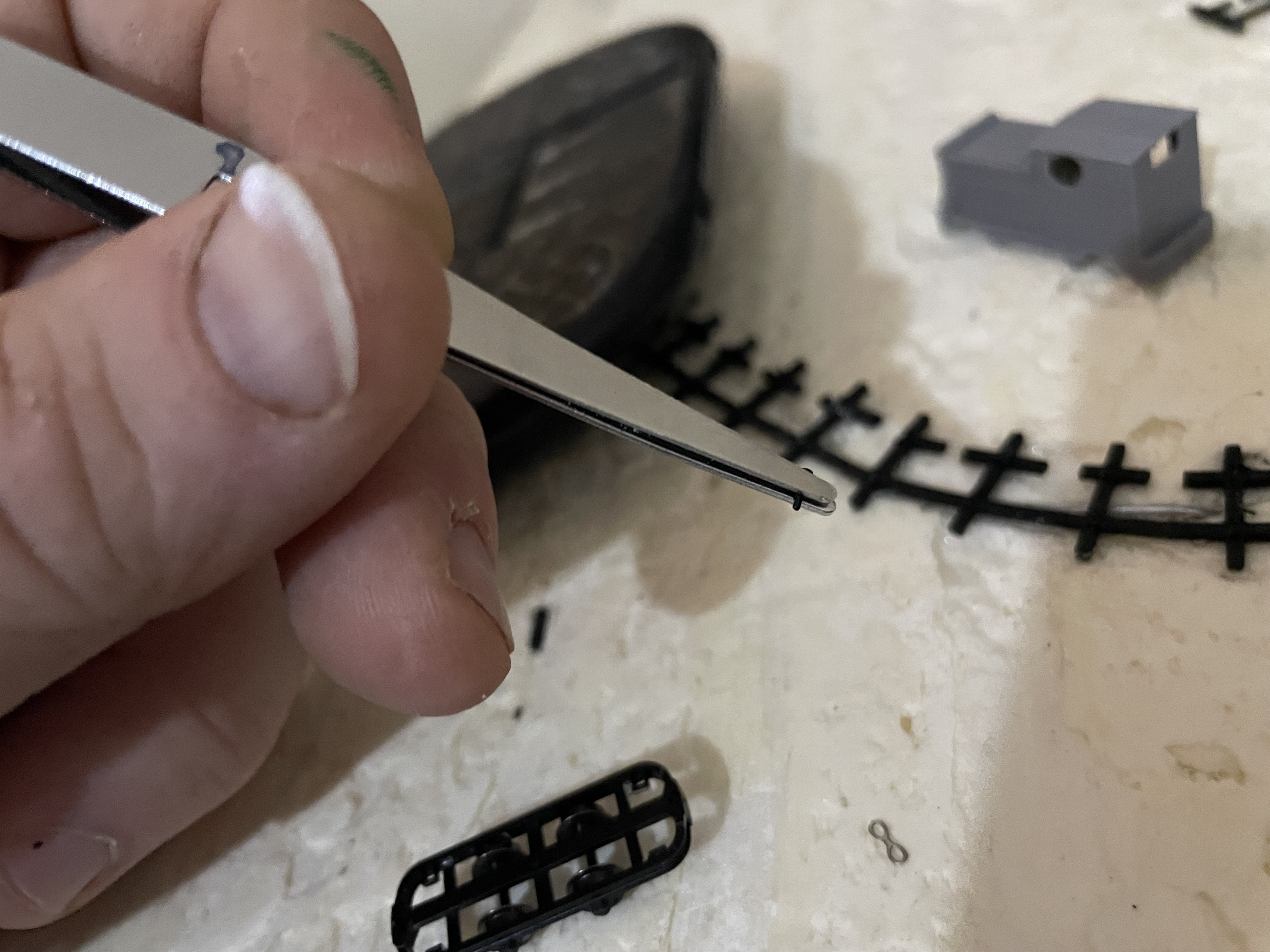
Prototypiclly ccurate coupling system............
The little pin then flew away, never to be seen again.............
-
 5
5
-
 1
1
-
-
-
Everything runs on the command station,
the coding is a bit clunky. but its not really that bad once you get your head around it. things can be coded to happen automatically on startup or only when you trigger it from the controller.
-
1
-
-
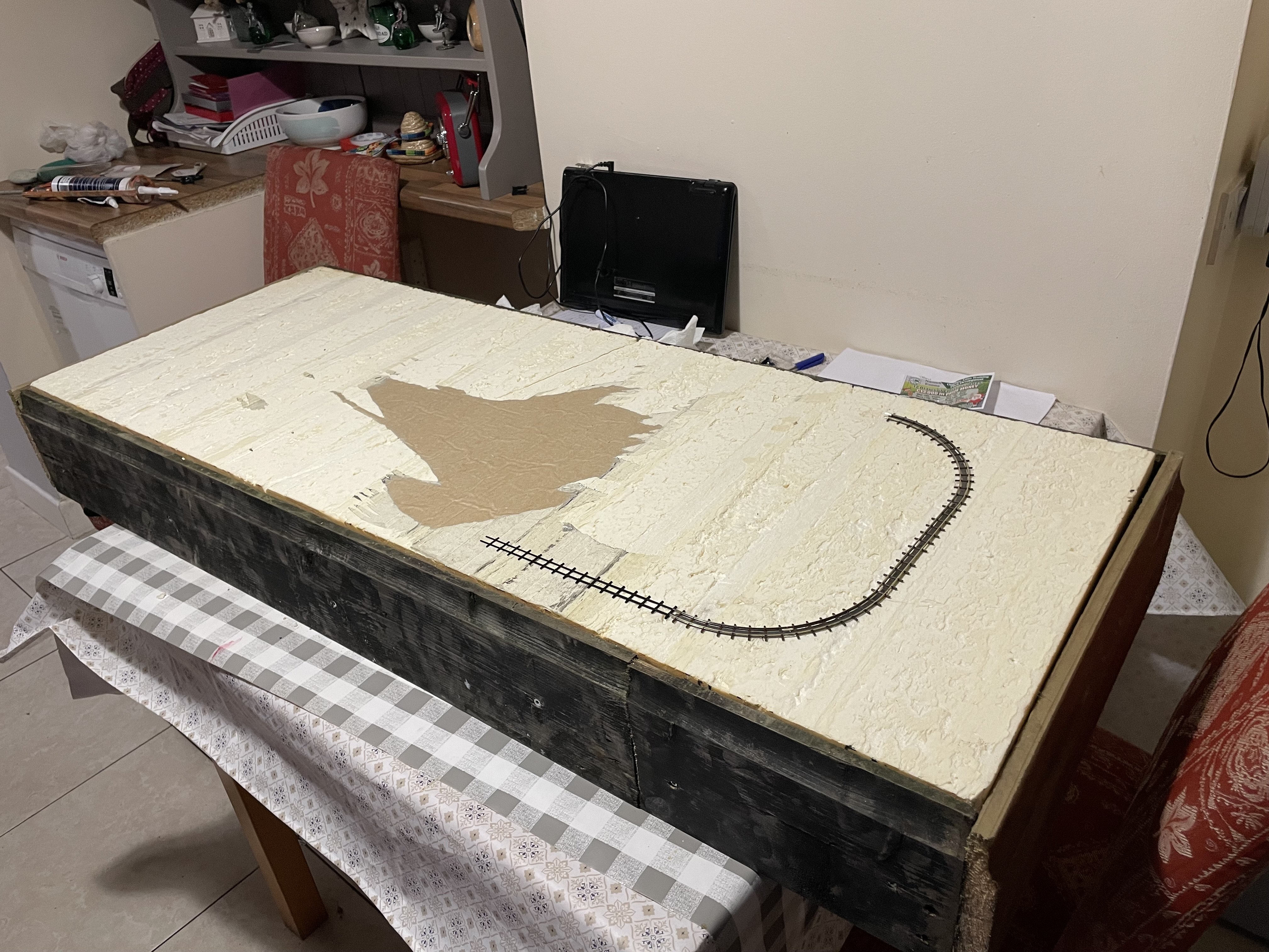
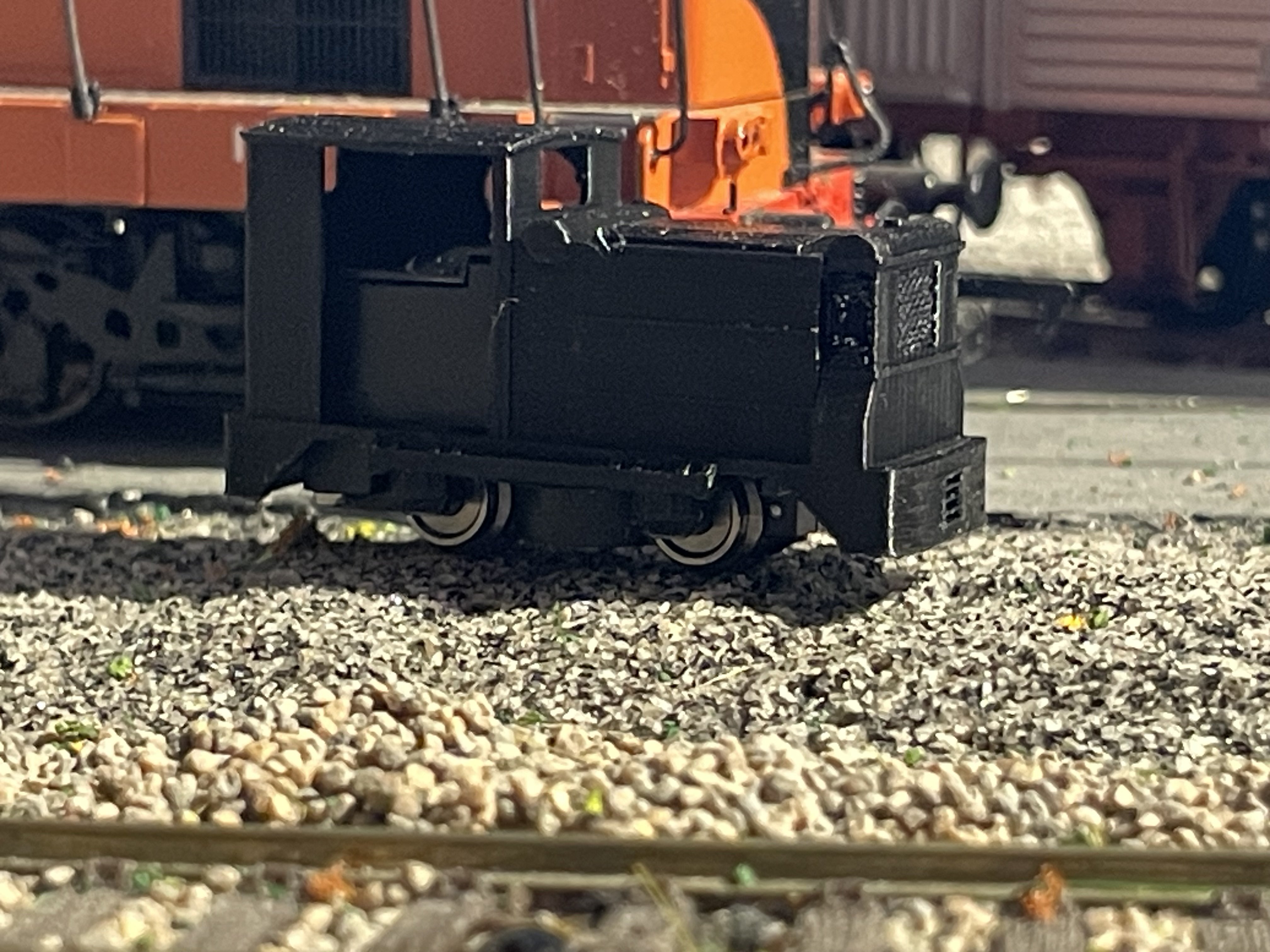
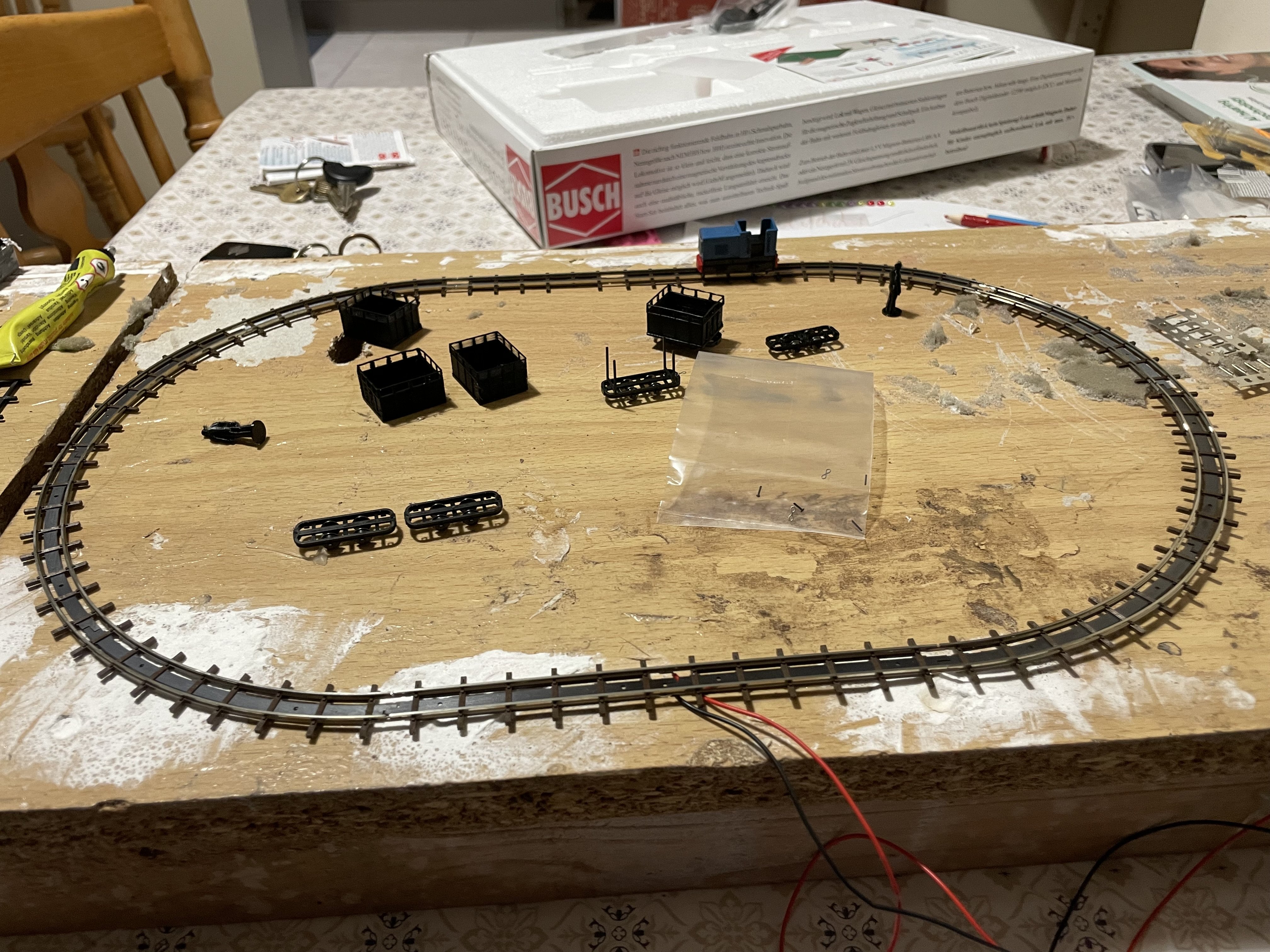
First run of the Ruston and first run on home made track!
-
4
-
 4
4
-
-
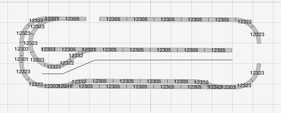
Unusually I am only playing with the track planning stuff now, ive been too engrossed in other aspects of this project that it has gotten away from me.
I wanted to really wind up my search for the site and i had not yet finalised on a base board size, so it made most sense holding off until now.
This is sort of another reason i have gone for h0f over 009, it is MAD what you can fit onto a medium sized board. I am working with 4 foot by 1 and a half foot.
upon completion of my research I have come to the conclusion that i need to model either the factory or the lansdale yard line or some sort of hybrid of both which would probabaly become too messy and detract from the realism.
For this plan, on one side of the board could sit the yard with the loop and tippler/conveyer, trains would leave along the right hand exit and travel around to the point. this area would be modelled as the branch line from the yard to bog.
Anything beyond the turnout can be considered bog, with a scenic break to disguise the loop back into the yard if the train goes straight.
turn into the left and you get a long siding for peat harvesting and a shorter siding for tracklaying and refuelling trains as is typical on a peat bog.
Operationally we have continuous running or we have a system whereby the train of empties is hauled up to the point and the main loco is uncoupled and the shunter comes out off of the small siding and hauls in the empties, the main loco can then be coupled back to the other end of the rake for the return leg of the journey.
A backscene separates the scenes but there can be no tunnels etc so it will be a matter of hiding the transitions with many trees!
I have a little celebrity cameo planned, but this will be revealed later!
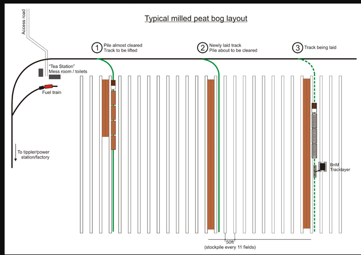
diagram here of a typical peat bog as a sort of quasi basis for my plan, no matter which line i build i am sure it will be taking basis from this diagram!
with this plan, prototypical train lenghts also become very possible without looking terrible.
-
4
-
-
we have liftoff!
-
5
-
-
Right so,
I have gone off the deep end altogether!
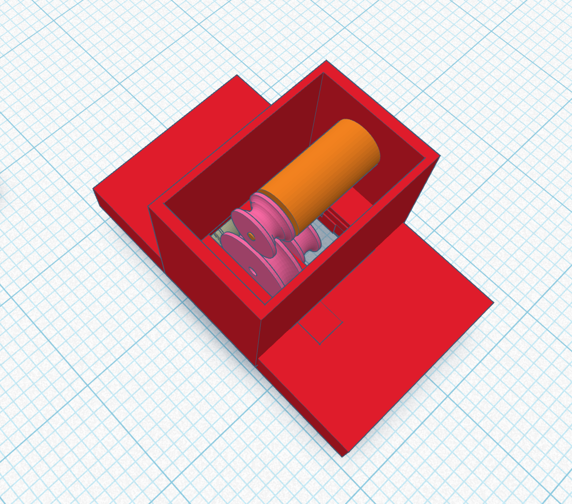
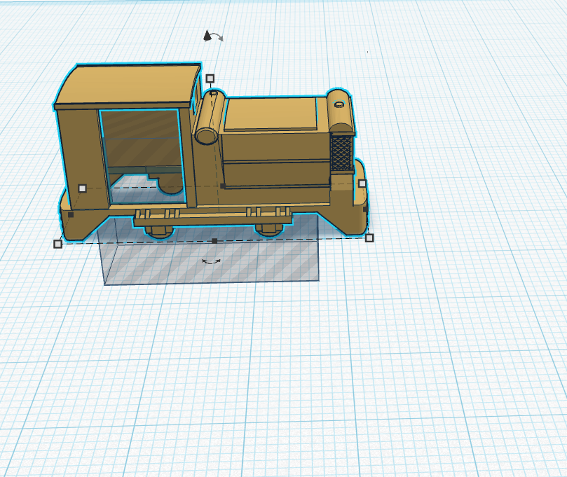
it was decided that i need a simplex, I just have to have one, however any 3d models of such are not of the type I need!
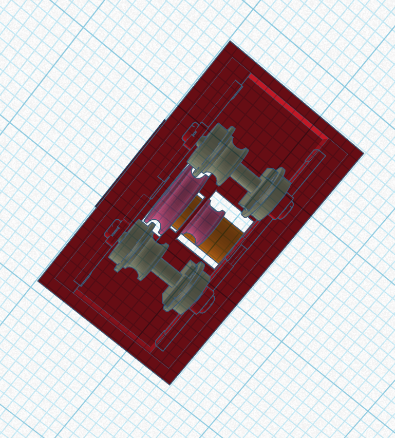
so ive set out in making one, and in a further bout of insanity as soon as the chassis was designed i said, hey lets see if we can motorise this thing before proceeding with the rest of it LOL
the design has progressed a little bit and the 4x8mm motor that @LNERW1 introduced me to on the other thread seems to be the only one i can make fit in comfortably.
Now initial designs had the motor mounted where the bottom pulleys are and a direct belt (O ring) connection to the wheels
The issue there is that the largest pulley i can fit onto the wheelset would be 4mm and the smallest pulley i can comfortably fit is also 4mm so this would lead to some fun gearing.
Moving the motor up in the housing and adding a lay shaft where i previously had the motor seems to be the answer. as soon as i did this i realised that i can change the motor pulley out for a set of gears to drive the layshaft with a proper ratio, the layshaft to wheels will still remain belt drive however.
Presumably I am going to have to rework this a few times and i dont actually have any motors yet so thats kind of it for now. but looks very promising.
I need to find printable gears!
-
3
-
-
Unfortunately not, I was thinking about it when I was looking at the first BNM site but i dont think I could justify going up there for what little is left.
There are also private property no right of way signs up going into the yard, so any such visits would probabaly have to be mandated by klassman themselves also!
I have done similar levels of obsessive research into the locos and will be doing a similar deep dive on those here soon.
After that i will be focusing on working on the layout, I actually havent got any sort of a plan at all yet, mostly cos of the wild goose chase i had been undertaking to find the railway

I have also become highly addicted to the 3d printing side of things,so this has taken loads of my time.I think it is going to be a big change in the hobby for me!
-
1
-
-
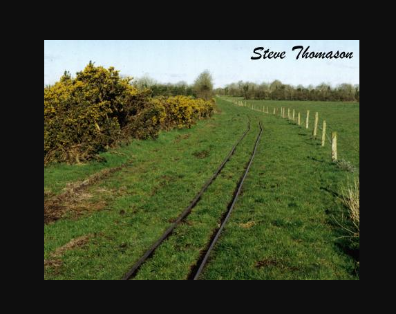
Here are the known photos of the permenant way that i have.
I have spent far too many nights on this, so to be able to match all of the images to locations on a map has been a big thing for me heh.
-
4
-
-
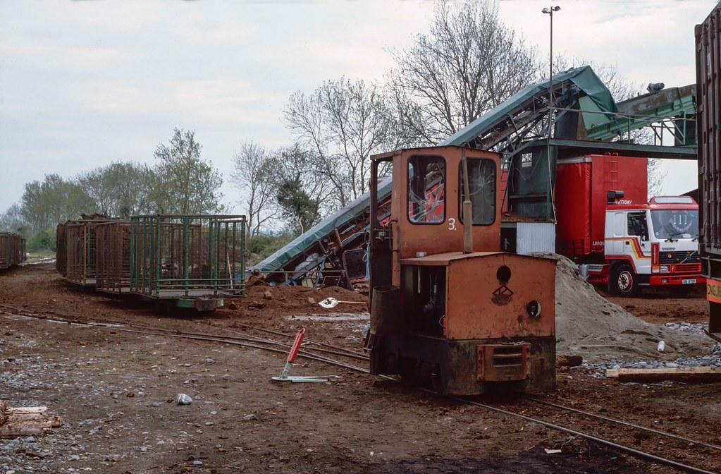
So this is where the confusion begins.
The Lansdale yard branch of the system is the most documented part, and along with that, the most interesting part, however in the available photography the location is credited as being at the works. There a permenant way documented that is around a mile long however with some sources saying there no rail link to the works.
a little contradictory!
Having searched the works area many times and coming up blank, as well as the area around smiths bog for any trace of anything I FINALLY had a breakthrough.
A long time was spent trying to geolocate any trace the elevator in this photo around the works and I just could not make sense of it being anywhere on or near the main plant.
After another while of searching I focused my attention on smiths bog. still after another few evenings of looking i could find no trace of anything, then by chance i set the map imagery to 2024 over a random area and FINALLY I managed to spot a set of rails which were not visible on any other map and sure enough I was able to follow these back to a fairly nondescript yard,
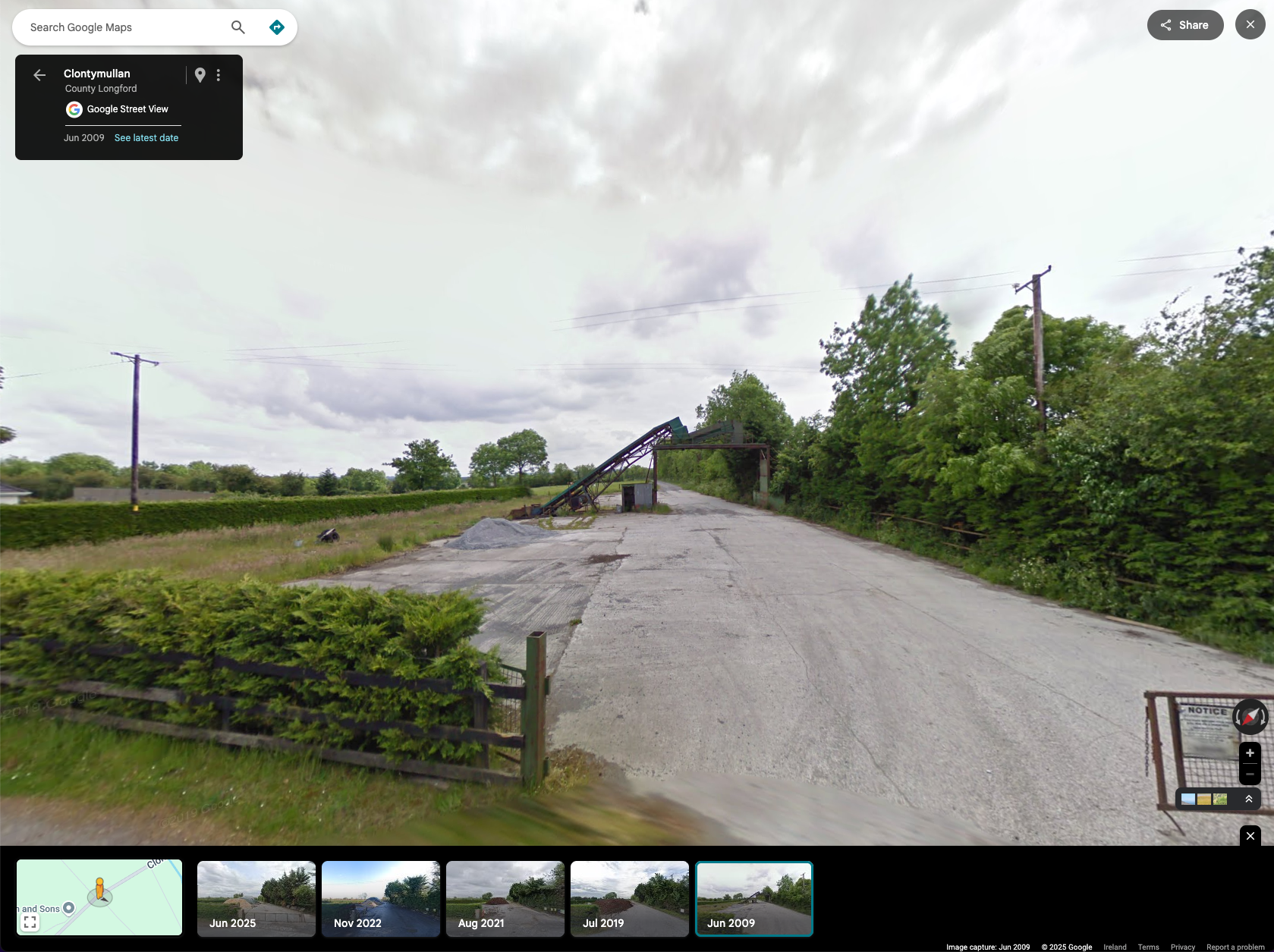
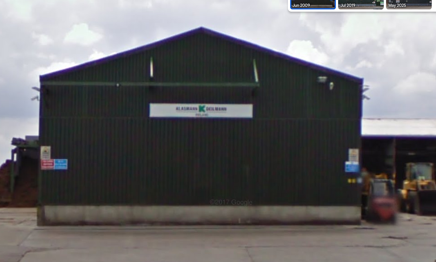
set street view to 2009 .... AND
https://maps.app.goo.gl/YNqCSkfhH1pabVCV6
THIS is lansdale yard.
THIS is the proof! the 2 tracks are still embedded just like in the flickr photo above!
https://maps.app.goo.gl/VCSP532Zt194LtAZA
from What i can make out, this is a surviving level crossing. you can follow the tracks down to smiths bog and back into that yard but you can see where it breaks up at one point, it is said that this branch line flooded and this was the final nail in the coffin for the railway here.
-
4
-
-
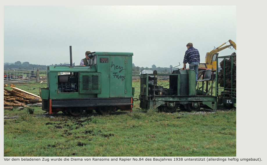
On 21/10/2025 at 11:18 AM, Mayner said:
Midland Irish Peat (Klasmann and Deilmann) had a (possibly 2) 60cm (2') Gauge systems
This particular trope has been really annoying me as i have struggled to geolocate some of the photos whilst others were fitting into place perfectly.
There are infact 2 systems and possibly even a third that isnt documented online but thats speculation untill I see proof.
the locos and rolling stock were moved from site to site as needed
I Initially had been misled as railmap online lists the system as existing northeast of rathowen but once i found out how to get historical google street view working it quickly became obvious that this was a BNM system.
The second piece of misinformation in my brain was that there was a rail connection directly from the peat works out to smiths bog and that lansdale yard existed close to or inside the peat works at killinagh to nessesitate this link
https://www.drehscheibe-online.de/foren/read.php?017,5203442,5203442 this 1993 visit lists the 2 sites as not being connected but this was the only real reference to this i could find. everything else was fairly ambiguous.
Last night I was able to locate landsdale on the map and absolutely everything clicked into place regarding the geolocating.
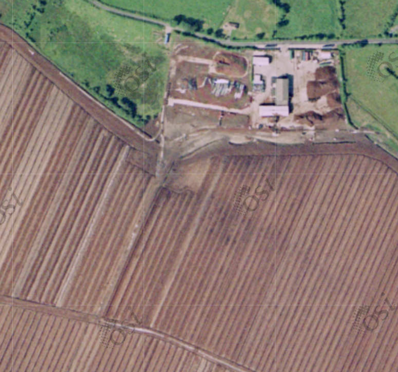
The first system was at the works and there is absolutely no trace of it but the wagons and some track can be seen on the historical imagery and it has allowed me to piece together the layout.
in this 1996 photo you can see the outline of the plastic sheeting they used to lay under the track. there is a line running down the left side of the works which is where they had some sidings and I think the maintenance area adjacent to the road around a sharp bend. the tippler and run around loop are not really visible in this photo. once track goes into the bog it becomes a temporary thing until they work the area and lift the track so no 2 aerials are really the same.
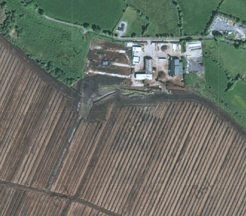
the 2006 photo shows us a bit more. the run around loop at the tippler is full of wagons and there is a separate rake of wagons on the other side of the loop, this is a really crude run around loop that is not symmetrical and this compares well on the photos.
the line that runs down the side of the plant and around the bend now leads into a little shed that wasnt present in the 1996 shot. the trackwork itself is greened over.
This was basically the whole system at the works except for the temporary layinga out accross the bog which would have changed semi often.
-
3
-
1
-
-
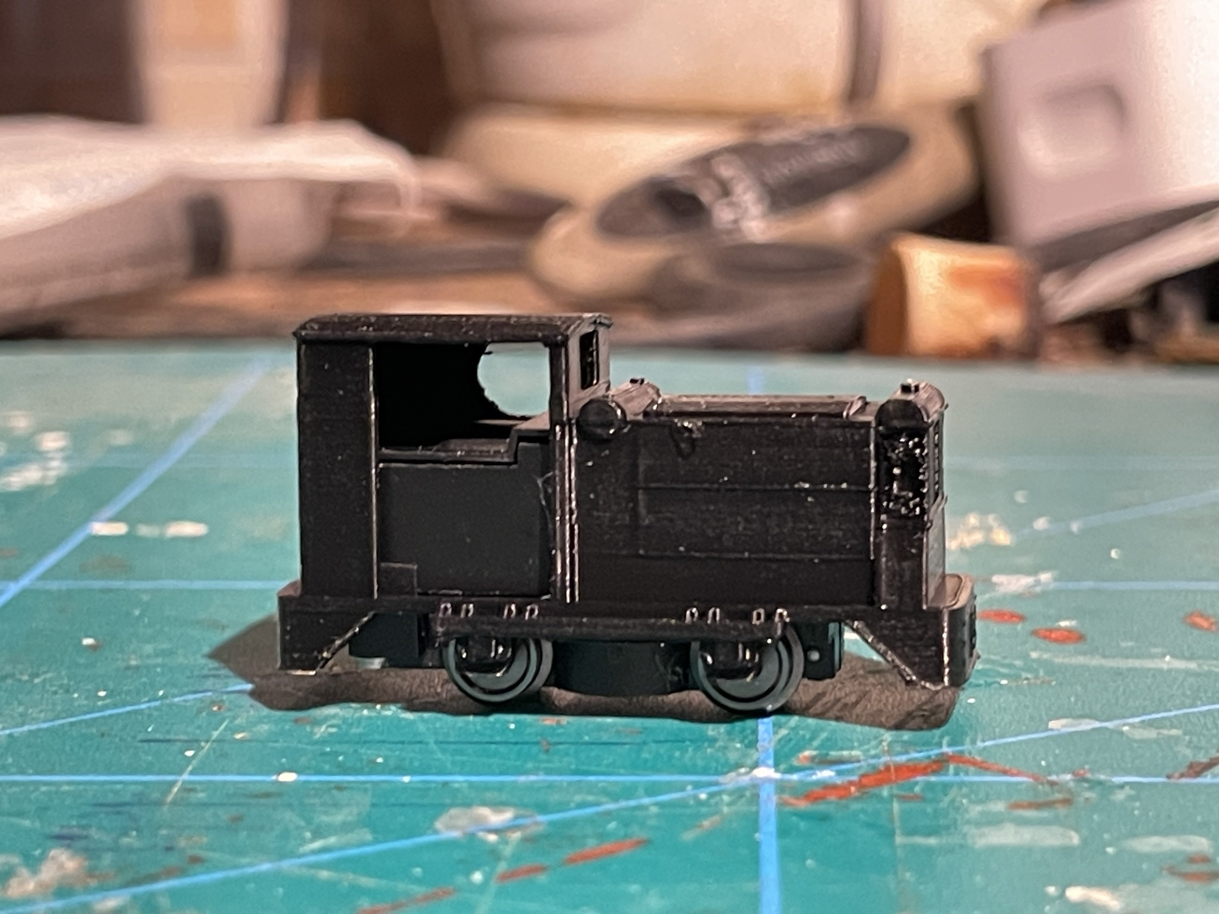
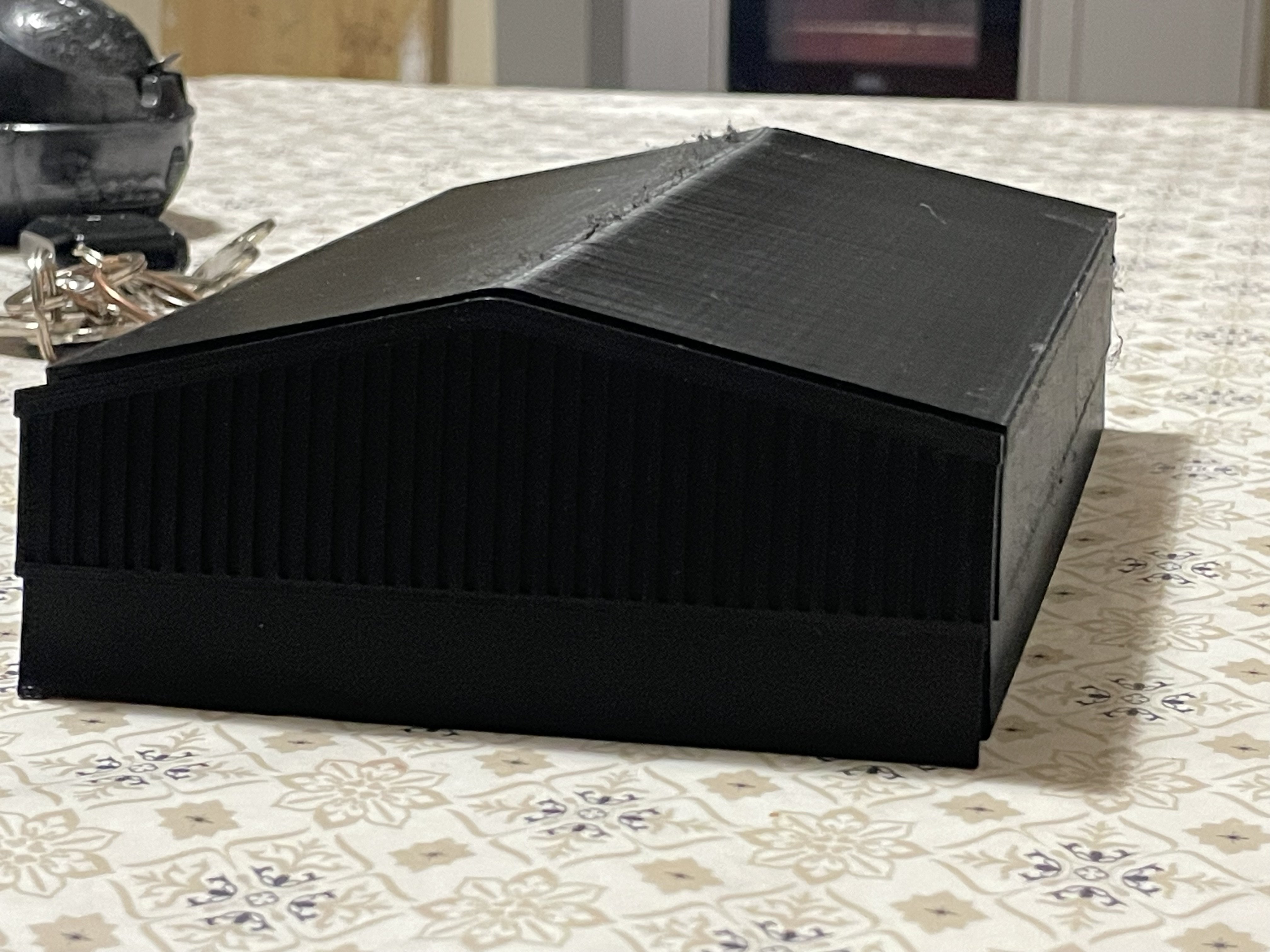
Spent far too many hours altering this last night to suit the chassis, glad with the overall fit though and it should be easier the next time i need to do such a thing!
This is printed with the 0.2 and otherwise default settings, took about an hour so not much longer than the 0.4 settings I had been using.
the most obvious thing is with the roof and the top of the radiator, the stepping on those curved layers iis much less noticable now
another print was done on finer settings which took around 5 hours, but honestly I did not see much if any improvement to that except for a smoother roof and the radiators didnt work on that either.
very happy with this overall, the front grille looks great and the one to the side of the radiators is not reproducing all that ell yet.
-
6
-
1
-
-
Do any of ye know how to actually control the camera in this?

its manageable but i find it a bit all over the place and sometimes if i go way off ill end up refreshing the page to get myself back to where i want to be.
-
1
-
-
Ive been at the same lol.
this is about the only cad program i can wrap my head around so far.
ruston has needed a load of adjustments to fit my chassis but its good now
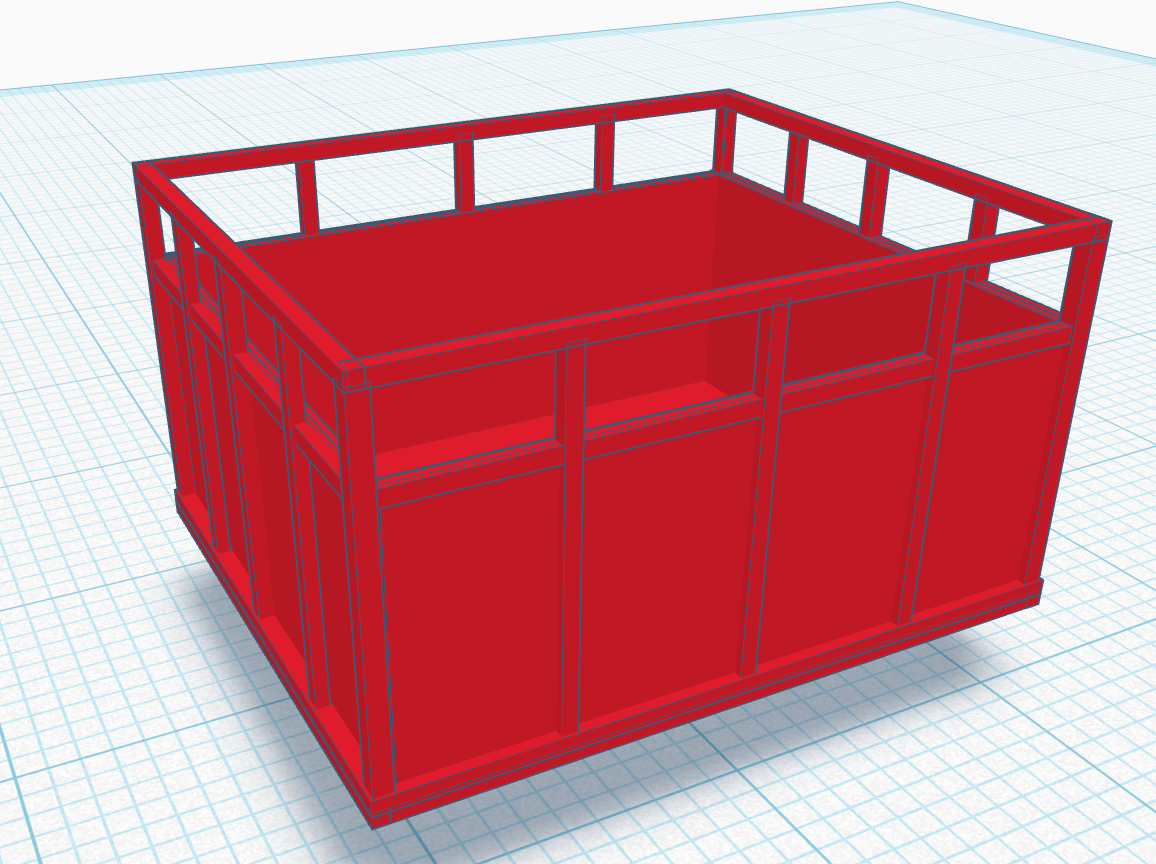
the turf tippler, fine tuned for symmetry LOL
-
3
-
-
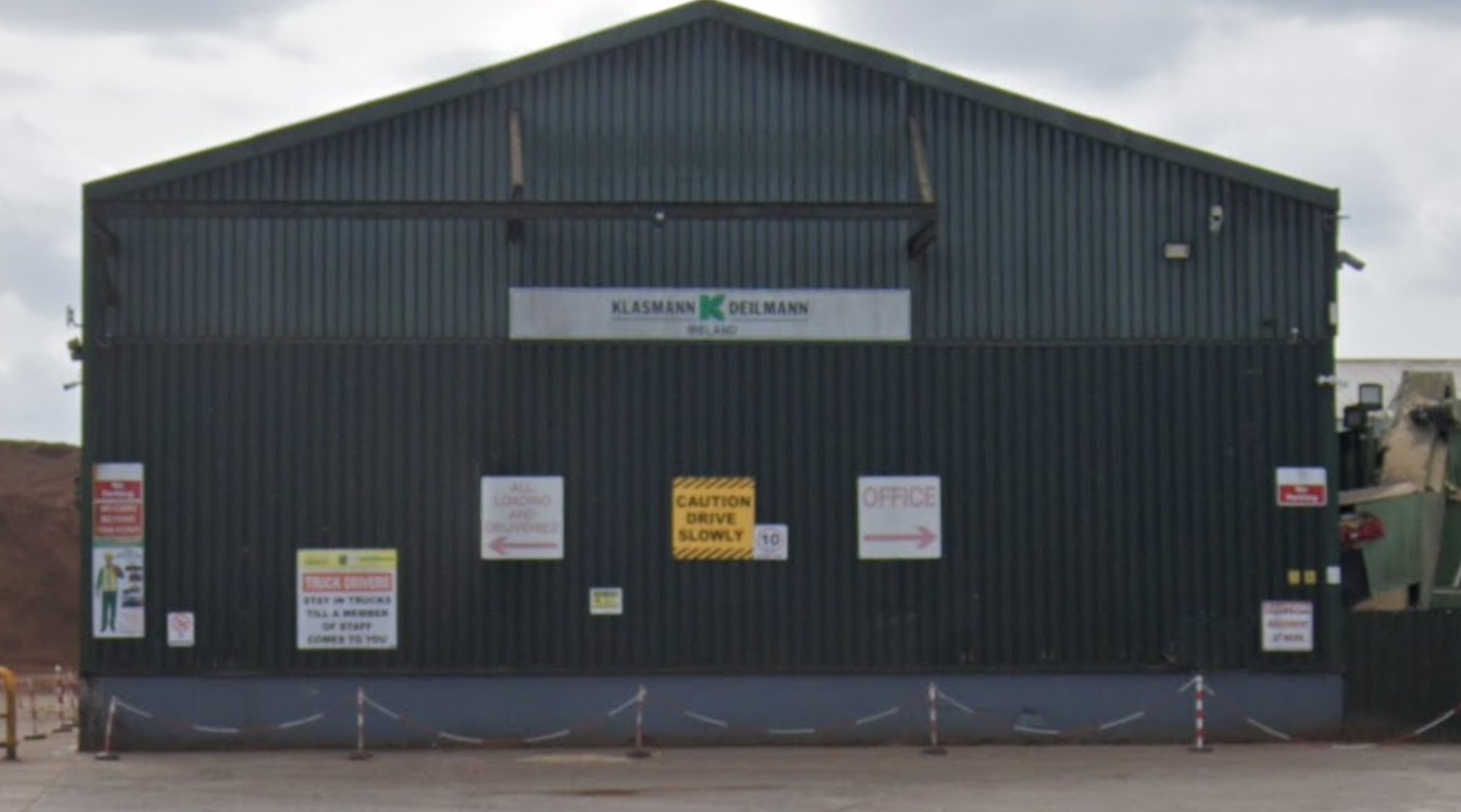
2009 vs Today, Health and safety have come a long way!
-
3
-
2
-
-
ahh my apologies, i hadnt checked your links.
the second one looks exactly like the motor in the busch chassis except the busch motor is 6x15mm so a bit bigger.
micromotor.eu exist as a firm that manufactures 12v replacements for busch.
I dont see any small enough for t but maybe the x12 could be fitted with some fettling
they look like a great upgrade for the busch system that reallly improves running
-
1
-
-
15 minutes ago, LNERW1 said:
Would any of the Tgauge.com motors be of use in HOf?
Nah, h0f is on z gauge track, i couldnt imagine working with T
-
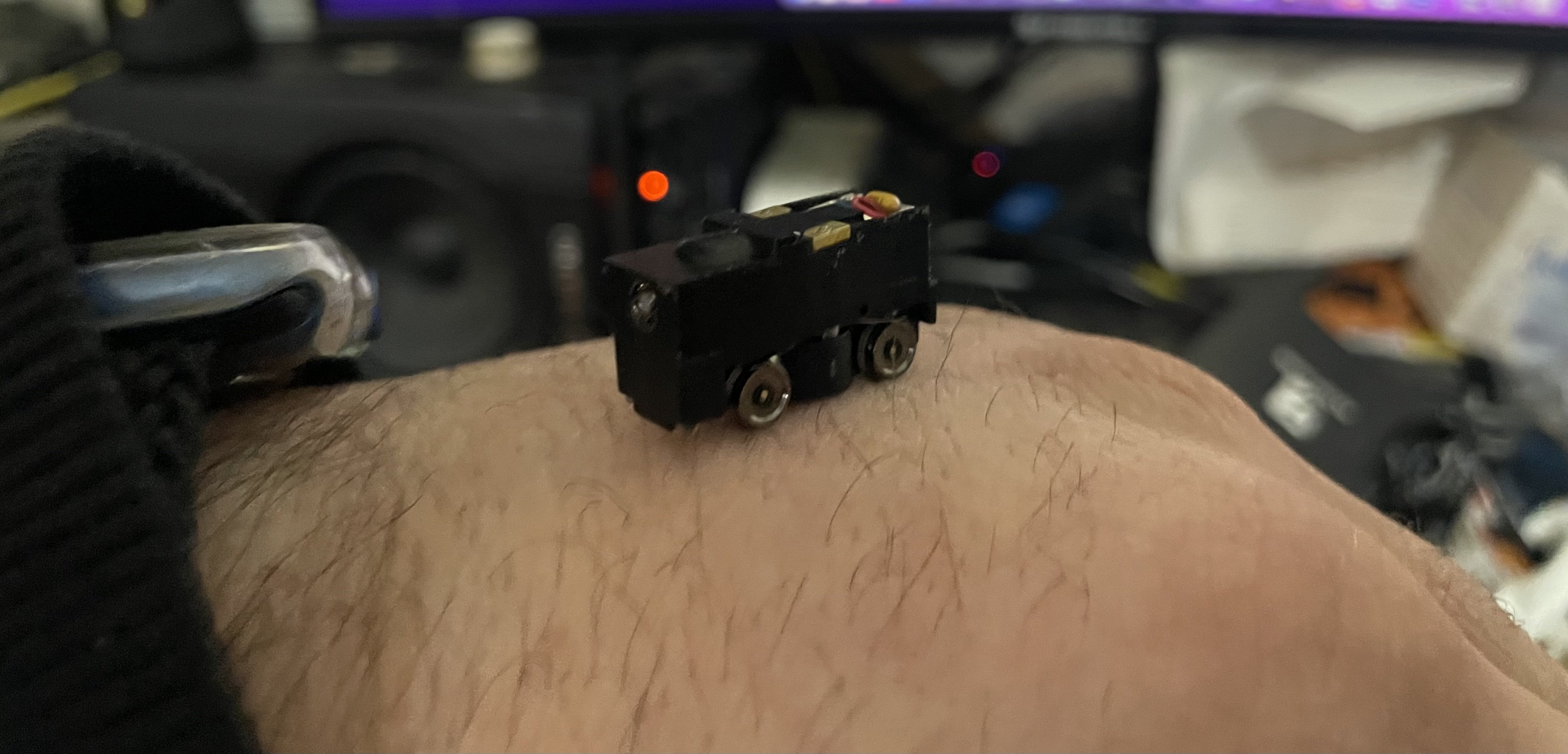
25 minutes ago, jhb171achill said:
How ON EARTH do they get working motors into stuff that tiny?
If extremely small scales like this, or Z, gain much traction, what about a 5mm gauge track to represent 5'3", and Irish models at a scale of 1mm = 1ft!
what I’m working with at the moment!
-
1
-
2
-
-
This is absolutely crazy to me
but its my kinda crazy
Having watched that peco 200 video recently, ill certainly entertain the idea since the space advantages are clear and i love a good micro.
I know nothing about T scale I will admit but i did investigate Z recently and i dont think I could go much smaller than 6.5mm gauge track and mechanisms.
If Z gauge was feasible. you can easily get points and set track as well as flexitrack. the cheapest running mechanism costs 30 euro or so from rokuhan
Dont let this deter you, people said the same things about N gauge for years.
one thing is, ive been told to expect a lot more track and wheel cleaning with this h0f scale, logically this will intensify further if we go down to T.
-
3
-
-
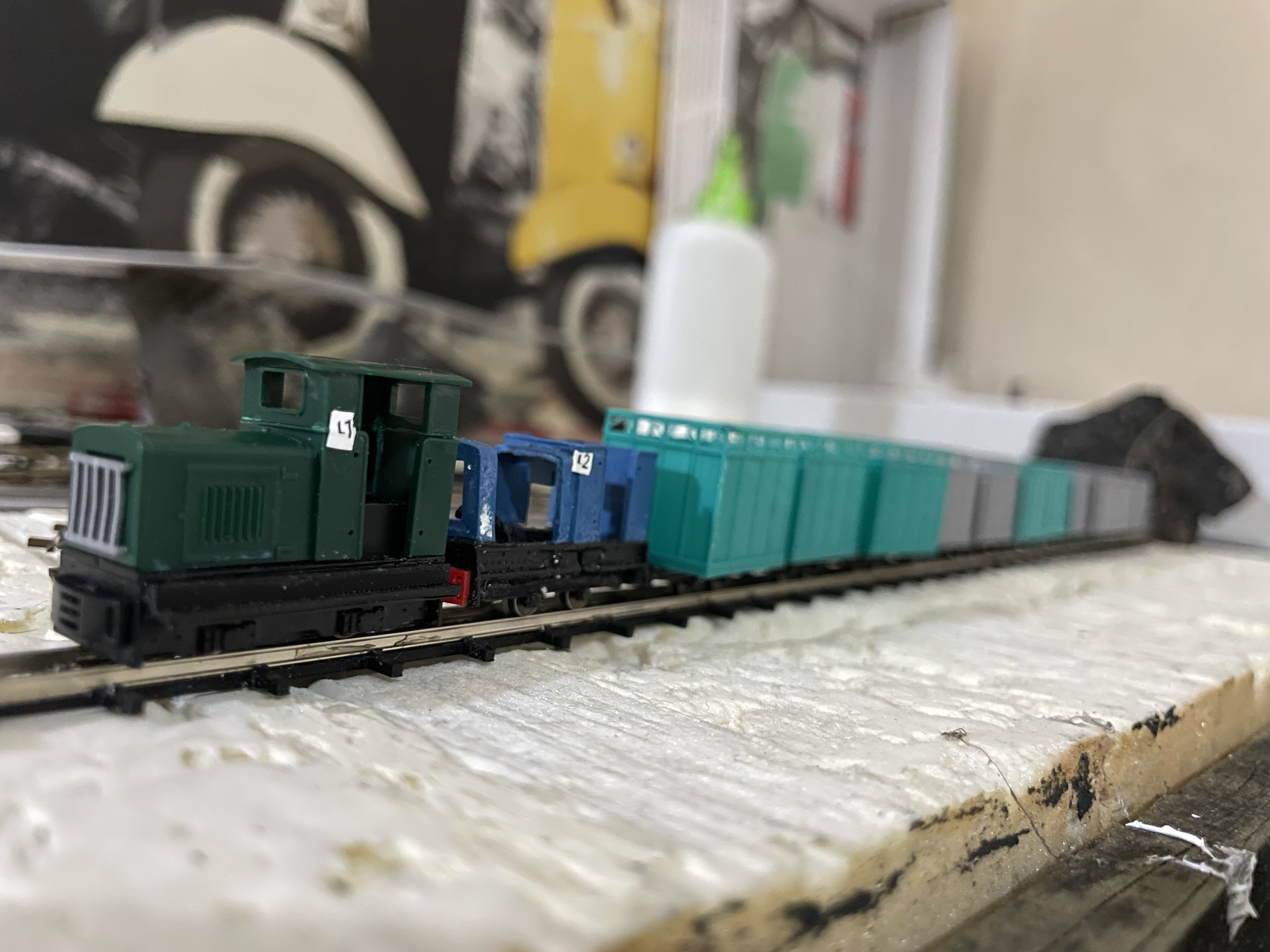
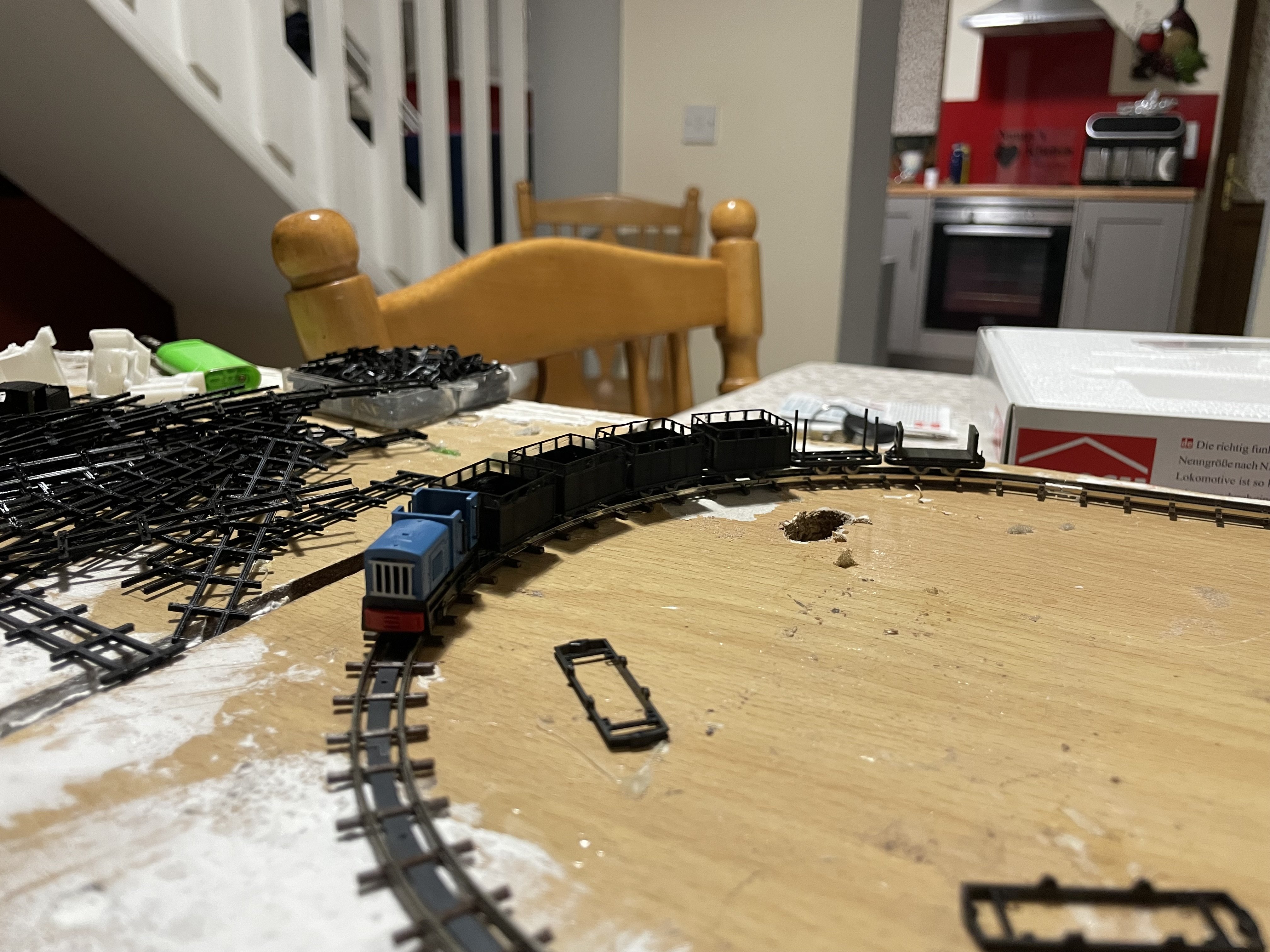
And a little while later we can finally add some wagons

pretty happy with the curves too despite how narrow they may be
-
6
-
-
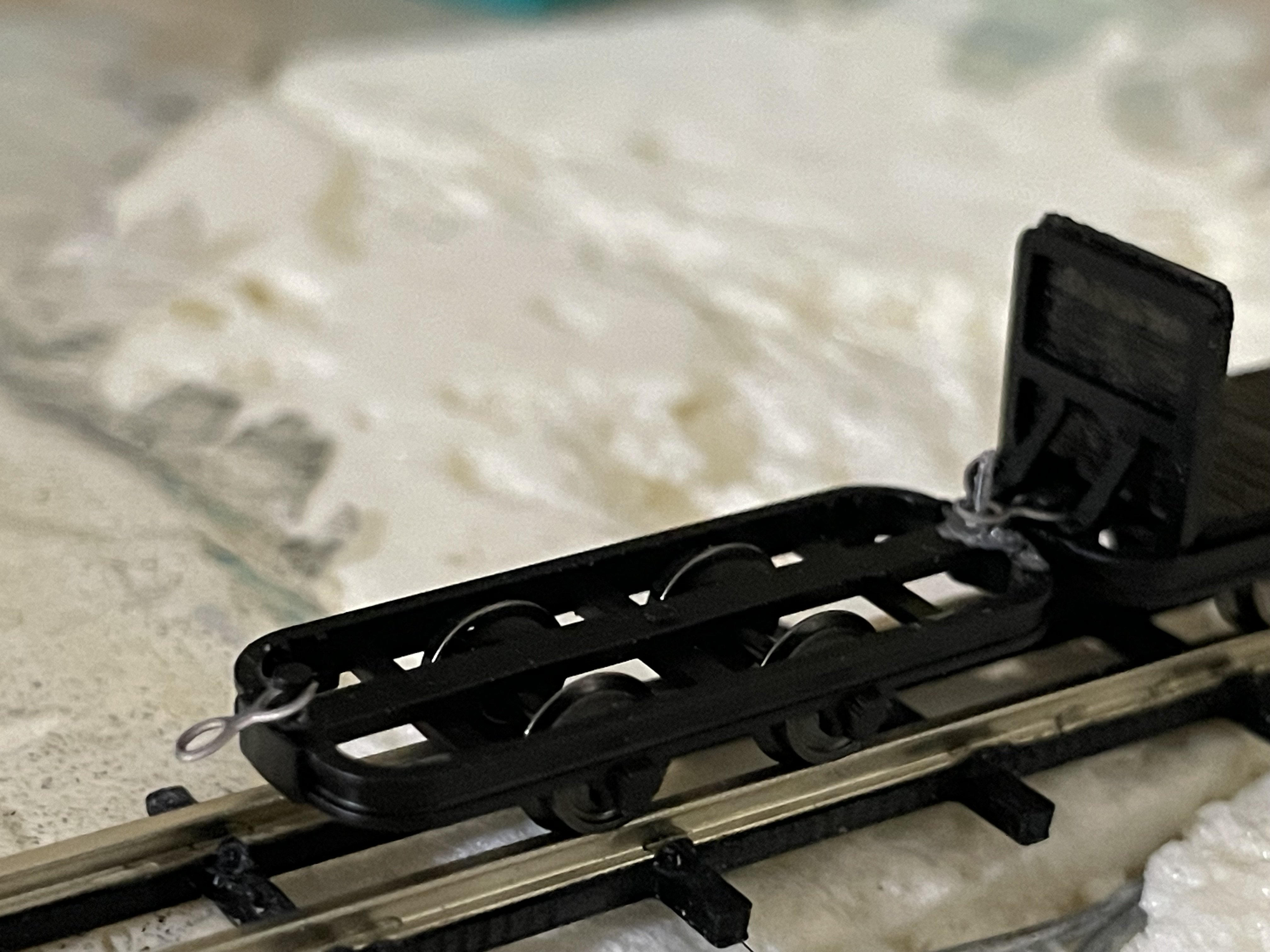
certainly in this case it has been beneficial to begin with the loop of set track.
this system is a little unorthodox in that there’s a magnet on the bottom of the loco and the black strip is steel that is used to pull the loco onto the track for adhesion!
my own track will have somthing similar hidden in the scenery however it was certainly mind boggling trying to see how it worked without actually having some on hand to play with!
the loco is running in and I am assembling 4 wagons on the Busch kits. This way I can get a feel for how the couplings work before I try to add them to my prints!
-
3
-
1
-
-
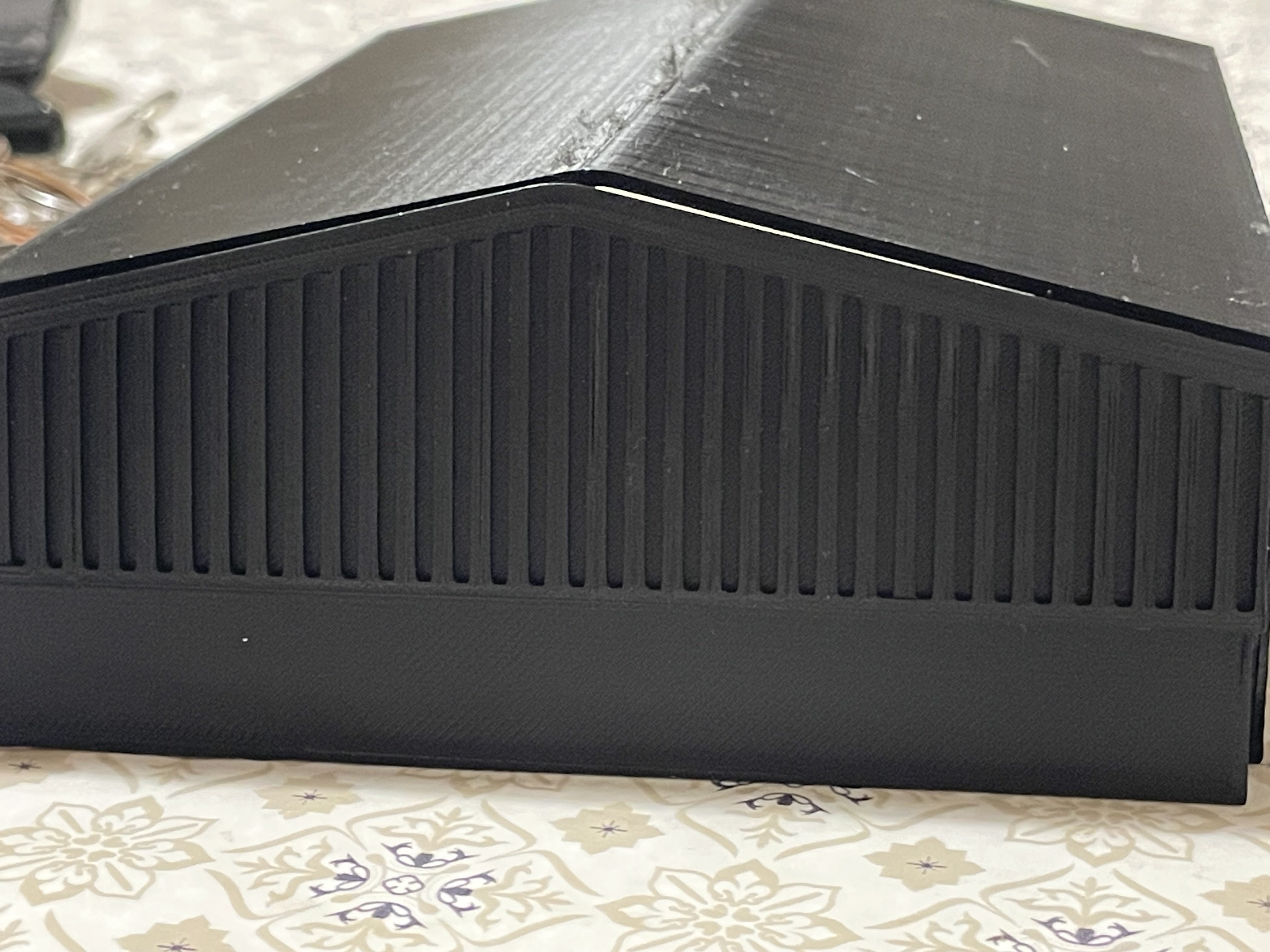
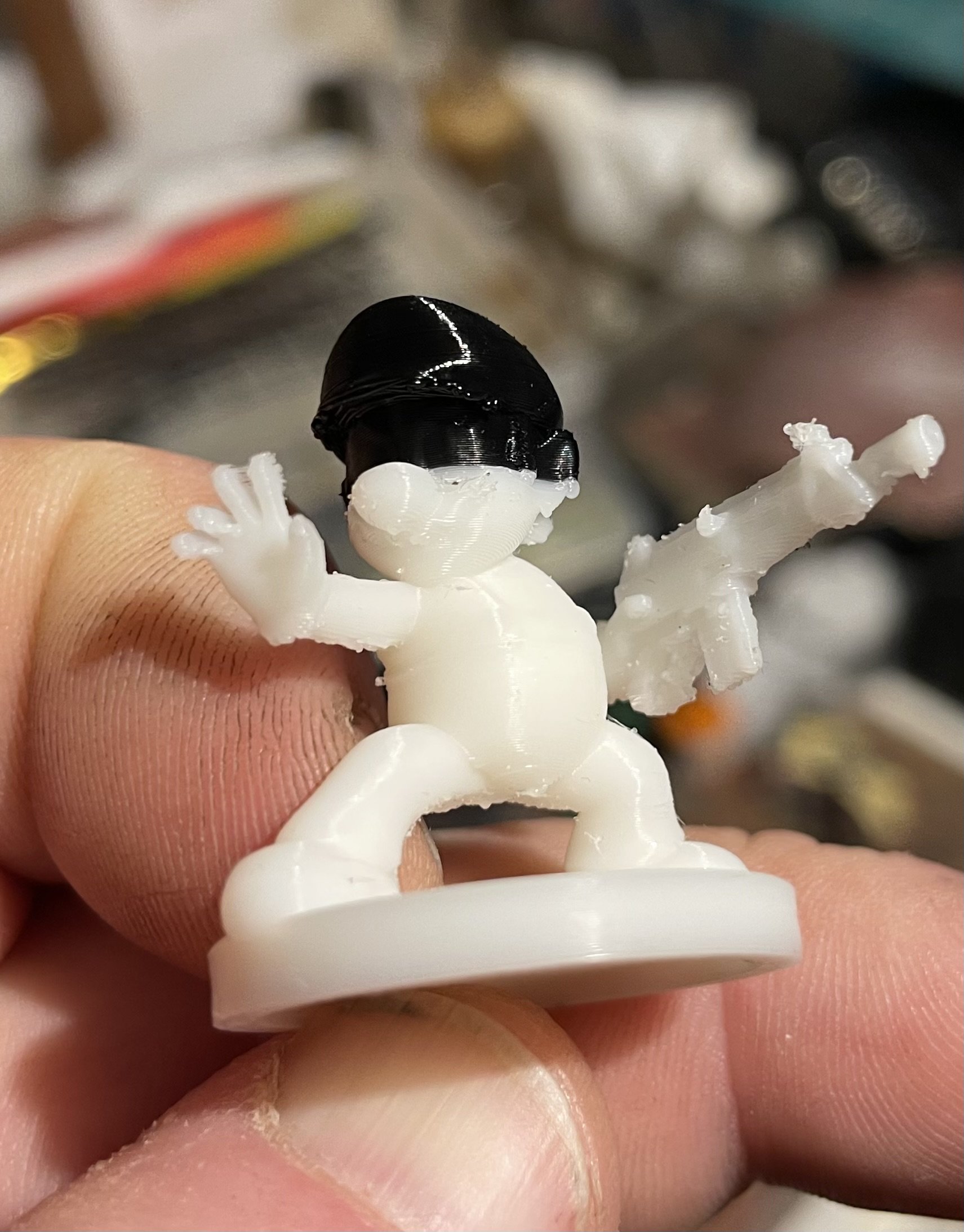
36 minutes ago, Flying Snail said:
Its very impressive to see the level of detail you're getting with FDM printing
It has certainly surpassed my needs and expectations.
this was a bit of a torture test last night!sadly the white filament ran out and the last little bit had to go black
ive ordered a 0.2mm nozzle which should actually increase resolute detail even further but the print times will double and this little guy took 3 hours as it is!
still not too bad once your patient.
-
2
-
-
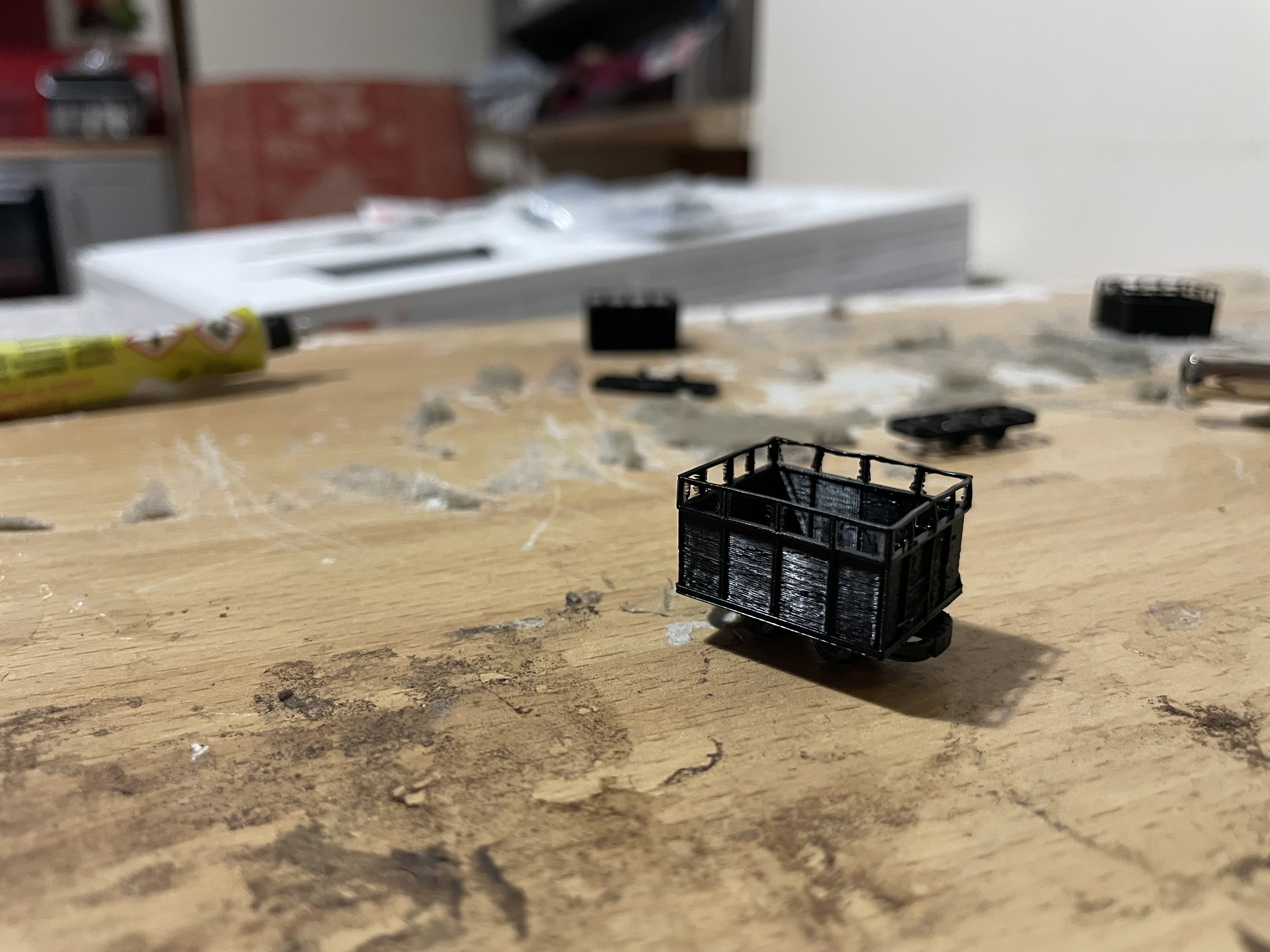
my own first self design is this very tiny turf tippler to sit ontop of the h0f chassis.
I need to order different filament before proceeding as this black stuff doesn’t feel as clean as the white stuff that came in the sample box.
overall I’m delighted with my results
-
2
-

Farcebook IRM RPSI Mk2 set
in For Sale or Wanted
Posted
In all fairness, I have reluctantly listed these based on the current price of IRM NIR MK2 pre orders plus roughly the price i have paid for the MM coach.
It was a very limited set and most likely, once it has left my collection I will never be in a position to get another one, particularly when other NIR coach sets have been going for similar money lately.