

Fowler4f
-
Posts
297 -
Joined
-
Last visited
Content Type
Profiles
Forums
Resource Library
Events
Gallery
Blogs
Store
Community Map
Posts posted by Fowler4f
-
-
Bring them all on !
-
 2
2
-
-
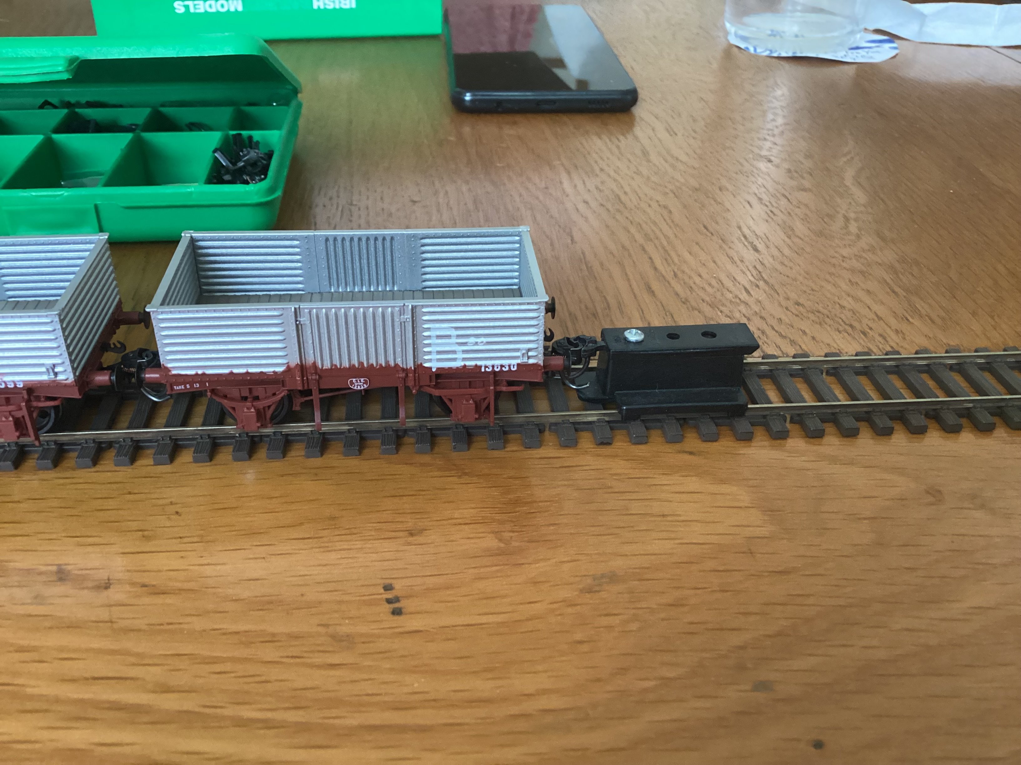
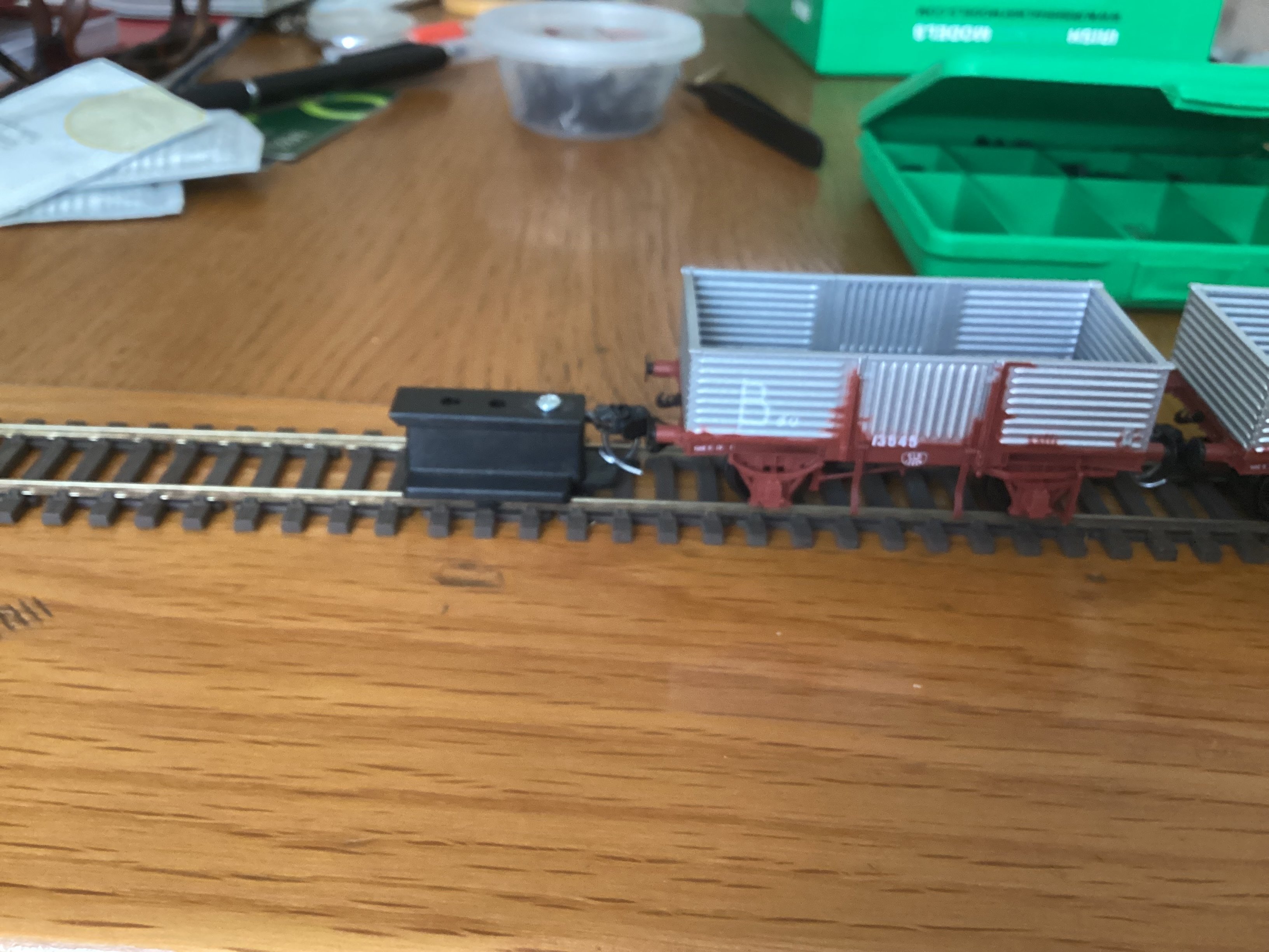
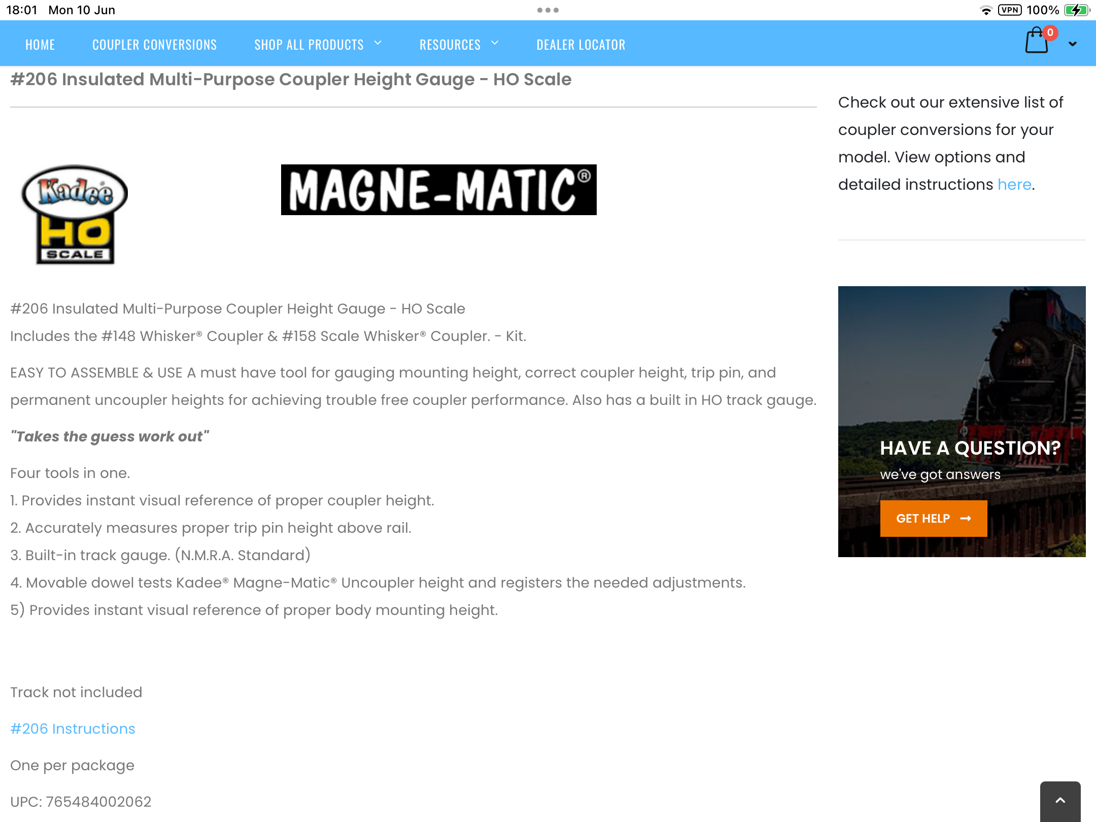
Just fitted Kadee No.17 to all my open wagons and tested with height gauge.
Spot on.


-
7
-
-
-
-
Looked on scale Studio website, sorted plus Ammonia set as well.
Thanks.
-
1
-
-
Thanks, I wasn’t sure if Des did them.
-
I have bought 5 JHA wagons and will paint them yellow, does anyone know who does Irish Rail Auto Ballaster transfers ?
Thanks.
-
 1
1
-
-
On 5/3/2024 at 12:39 PM, Noel said:
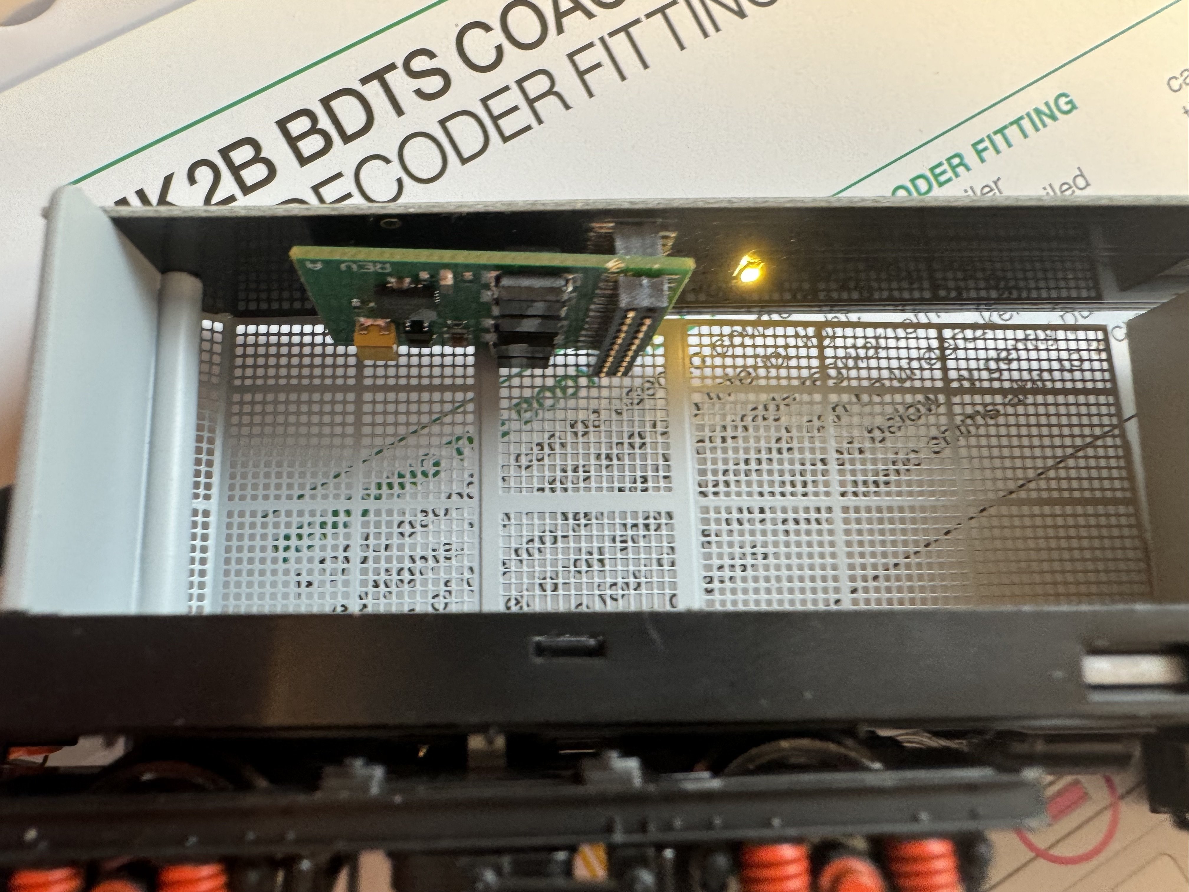
The NIR mk2 DVT needs a decoder if placed on DCC track (ie to get rid of the short and buzzing noise). So fitted a Lenz decoder to the driving trailer yesterday. Easy to get the body off following the instructions. To safely remove the blanking plate and insert the 21pin decoder in I removed the roof level PCB (easy 2 screws). Then popped it on the test track to give the decoder address 916. Body cable easily unplugs from the PCB. Easy Peasy. Magic wand works to turn the main coach interior lights on and off but not the front end of the coach since decoder fitted. I can't figure out which functions switch the other lights on or off other than the usual F0 for the running lights which alternate between white and red based on direction chosen. Very nicely engineered model. It would have been nice if the interior lights worked out of the box on DCC track without opening up the body to fit a decoder. The interior lights in other coaches and my other two sets work fine on DCC track out of the box using just the magic wand. Will have fun with these when I've completed the respray of IR 085 into NIR 112 livery. Happy days.
Hi Noel, if I understand it is the cab light you are referring to ?
I used DCC Concepts AED Decoder, setting CV 39 to 0 switched off cab light, also I gave BDTS same address as loco that is permanently to set.
In the 90's I used Lenz decoders and came with booklet. It should tell you which CV controls light function other than F0.
Trust that helps.
-
 1
1
-
-
*
-
 1
1
-
-
The Key Board Monkey, who at best can only Snipe, whinge & whine.
-
 1
1
-
1
-
-
When taken for a Fool, the Wallet shuts.
-
ZZZZZZZZZZ !
-
The 056s body on the irreparable A46 chassis will sit outside the repair shop awaiting the scrap man’s cutting torch !
-
The sooner the better !
-
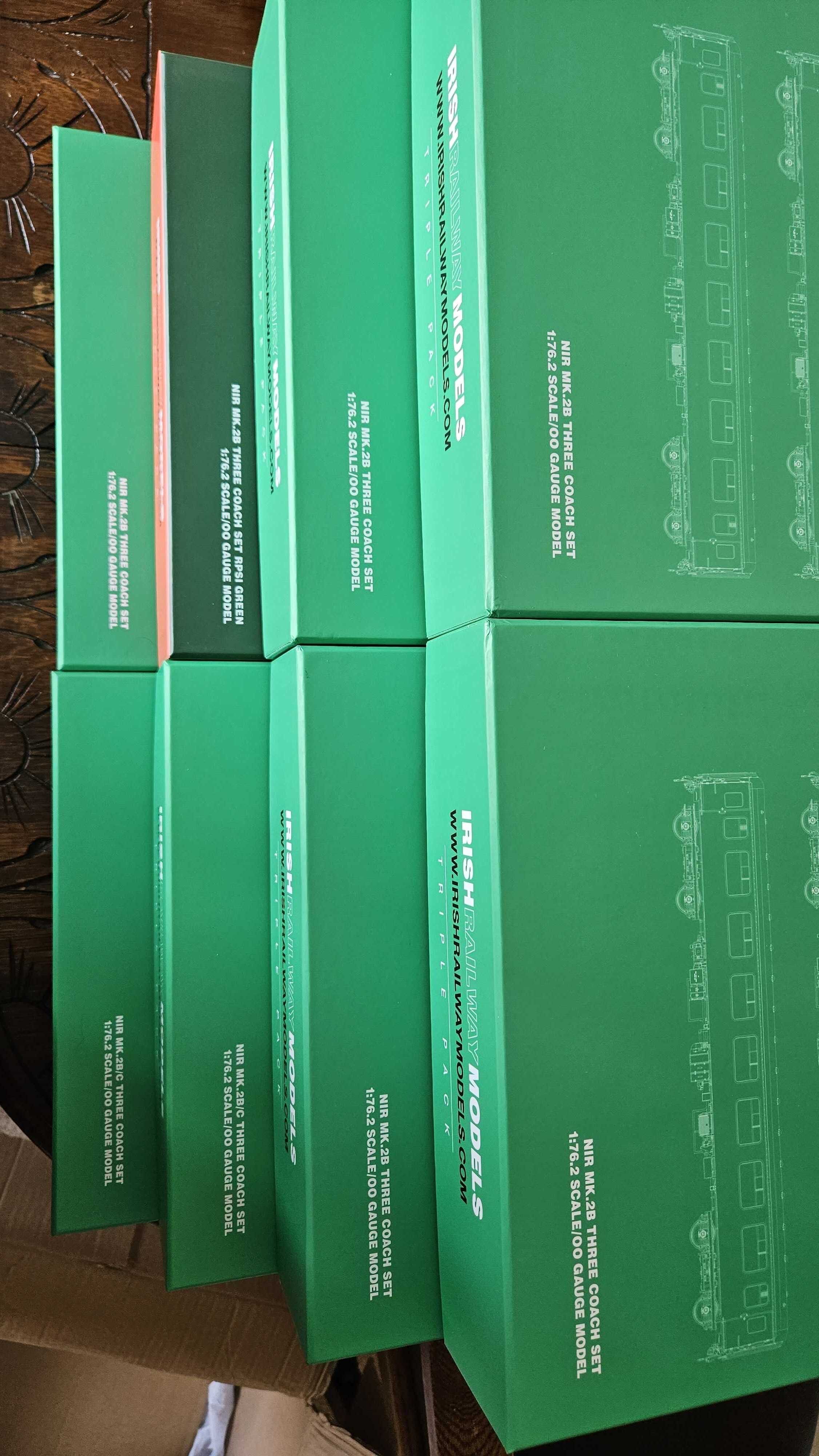
Looking forward to delivery.
-
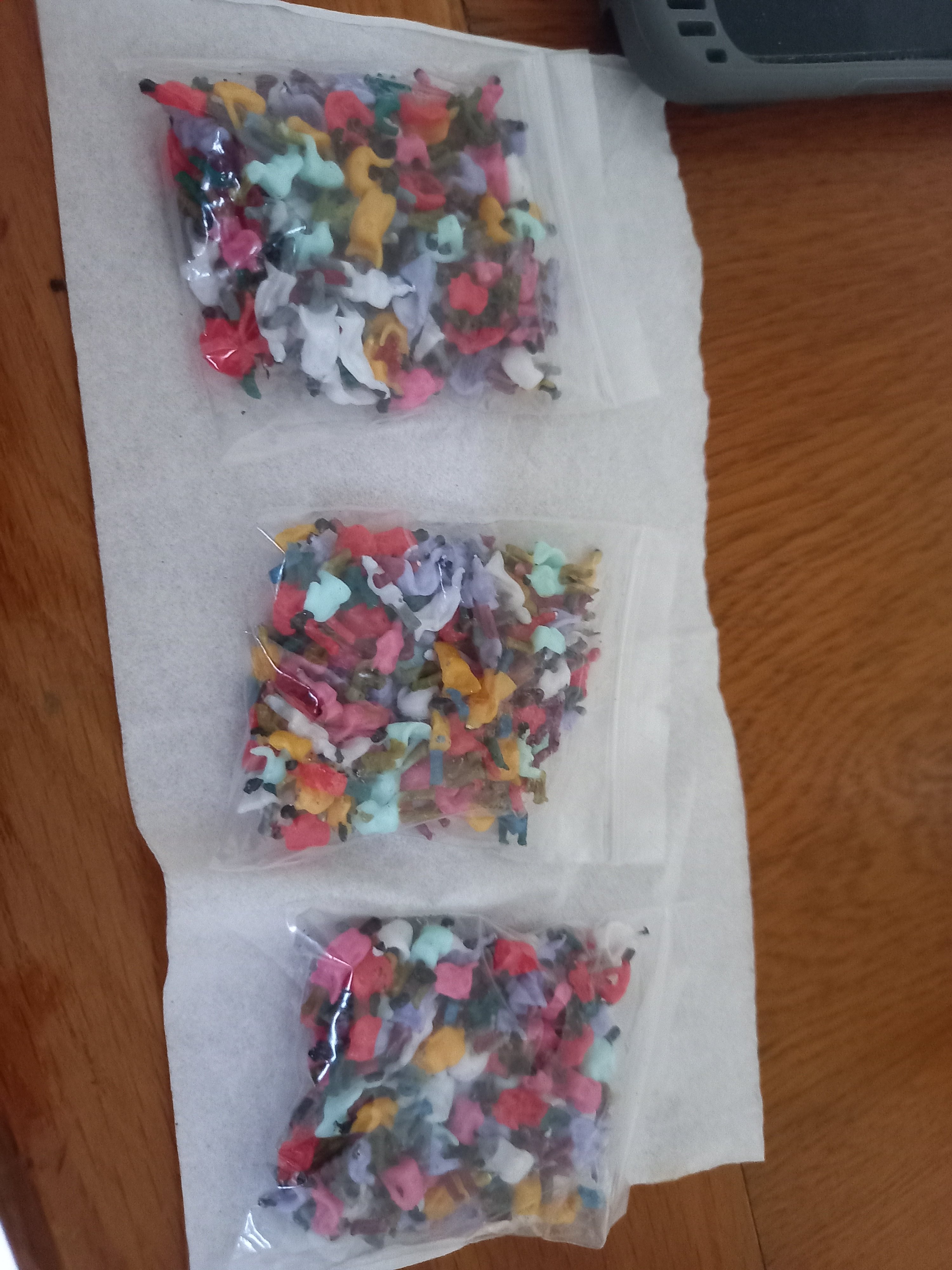
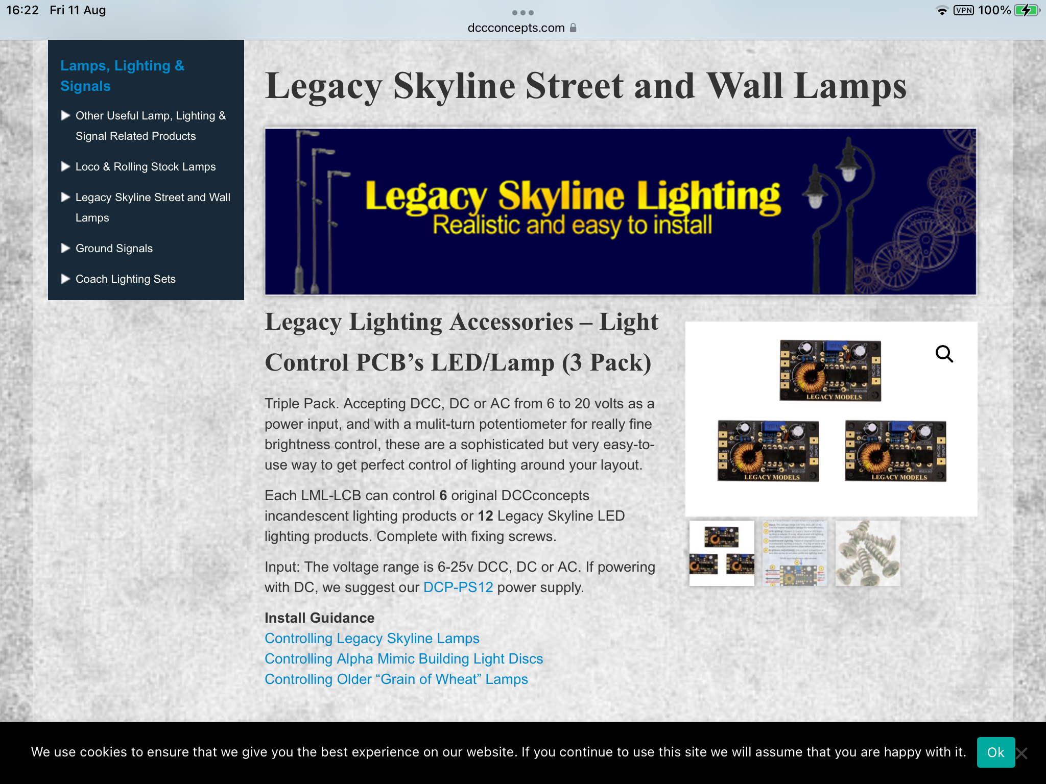
These lighting control units are a doddle, 12 LED’s per unit and no need for resistors.
-
1
-
-
4 hours ago, BosKonay said:
They’re here !
-
1
-
-
Always remember to wash your hands after handling solder.
-
I should mention that I have rewired all 19 of my A Class locos quite some time ago.
A46 met with an accident recently, breaking off both bogies, the drive shafts & buffers. I purchased a replacement loco 056s from Chris Dyer and swopped A46 body with 056s body, hence the need to rewire the loco.
-
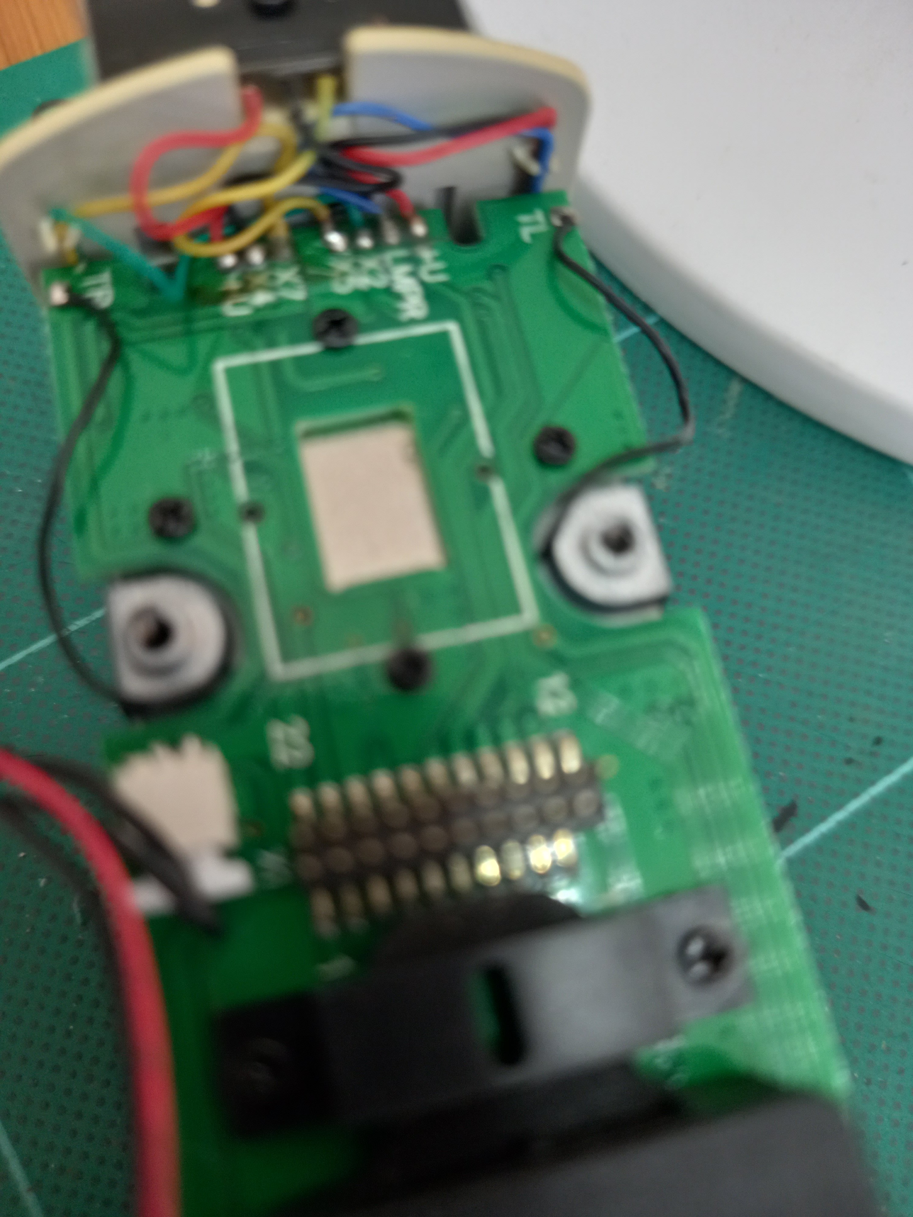
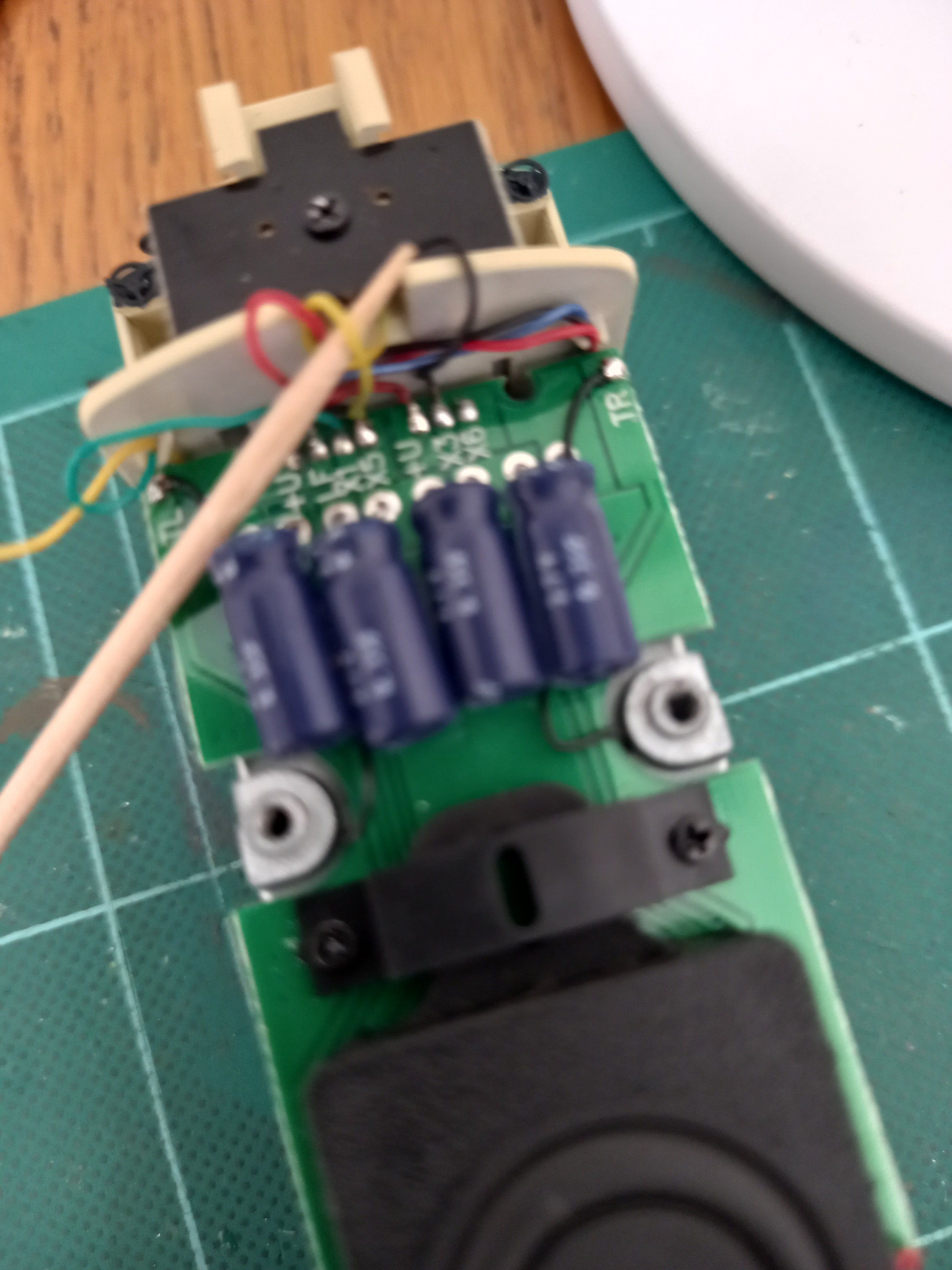
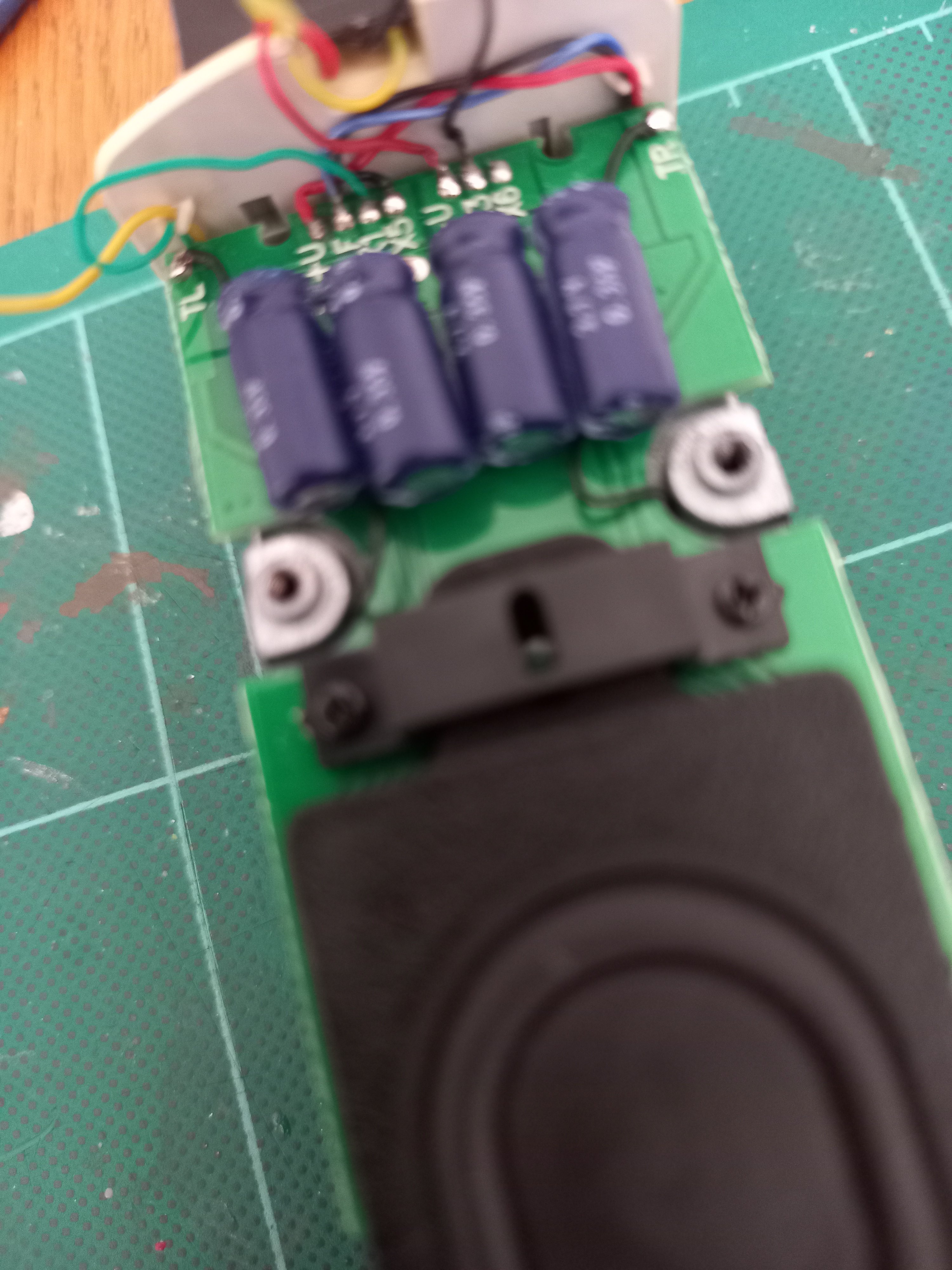
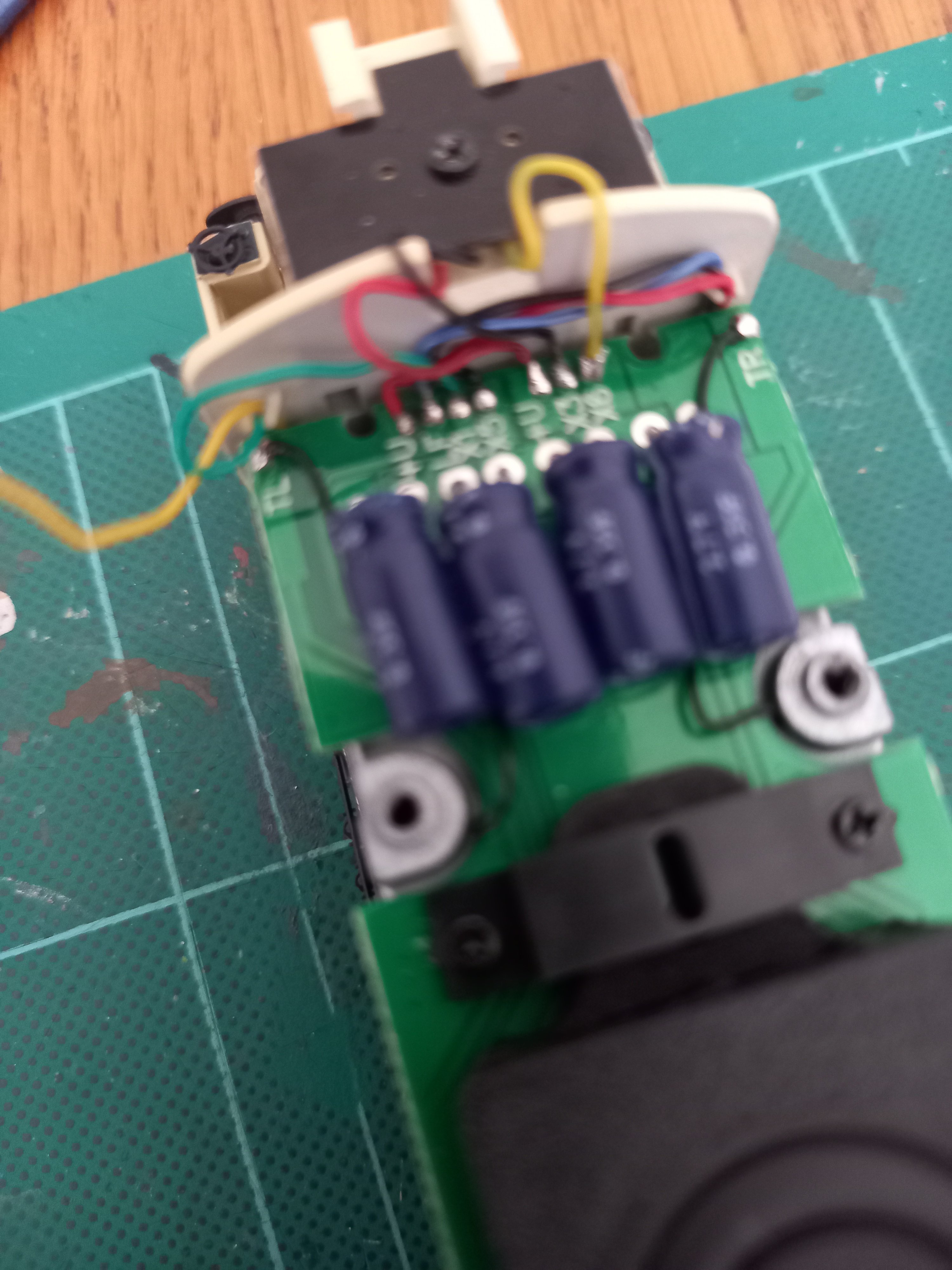
A Class Cab Light Directional Rewire.
All the wires that need swapping over are yellow. 2 wires at decoder end & 2 at stayalive/capacitor end.
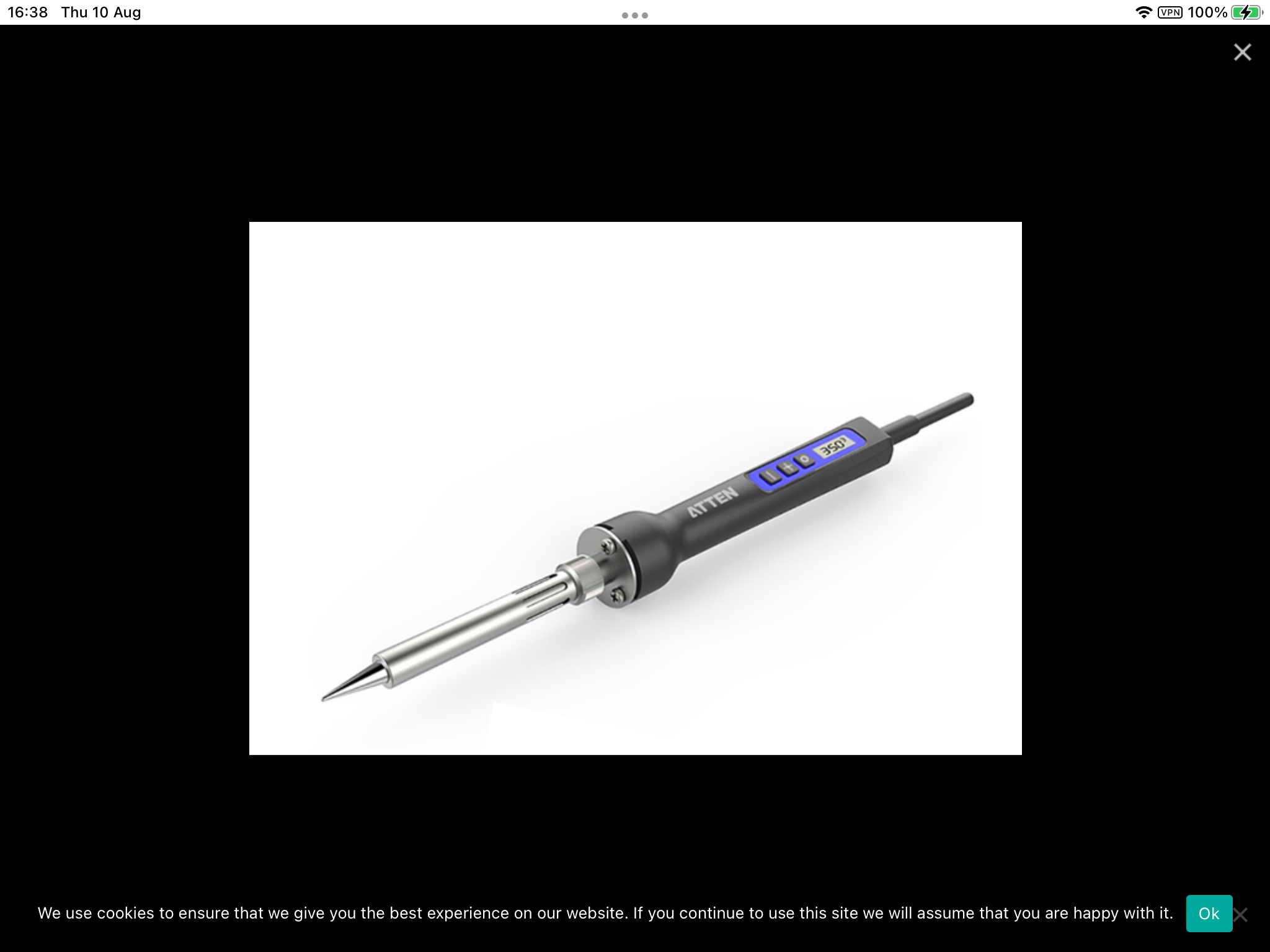
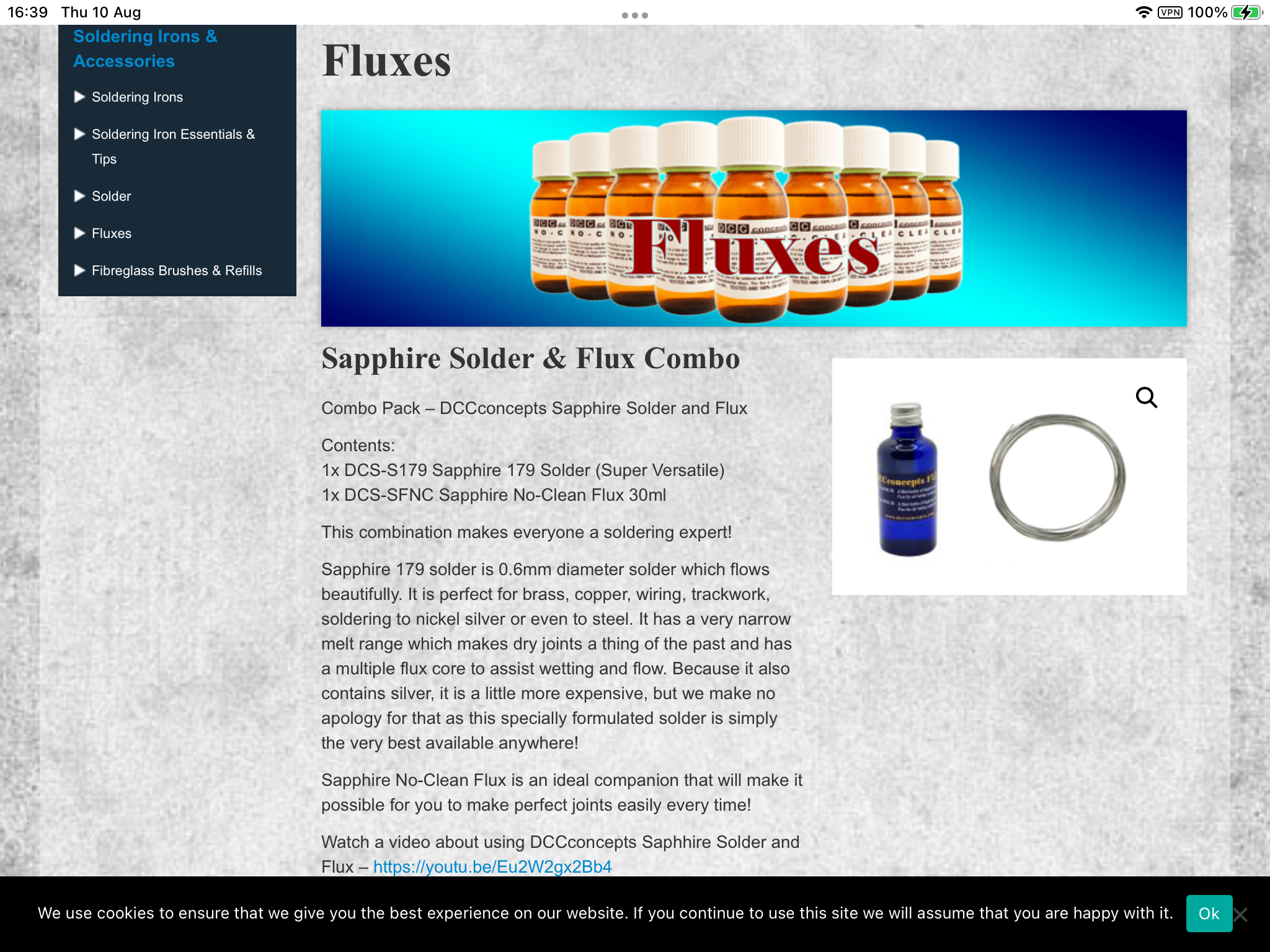
Tools needed : a good soldering iron @ 400° with a clean fine tip, solder & flux, a pair of fine nosed tweezers and a cocktail stick.
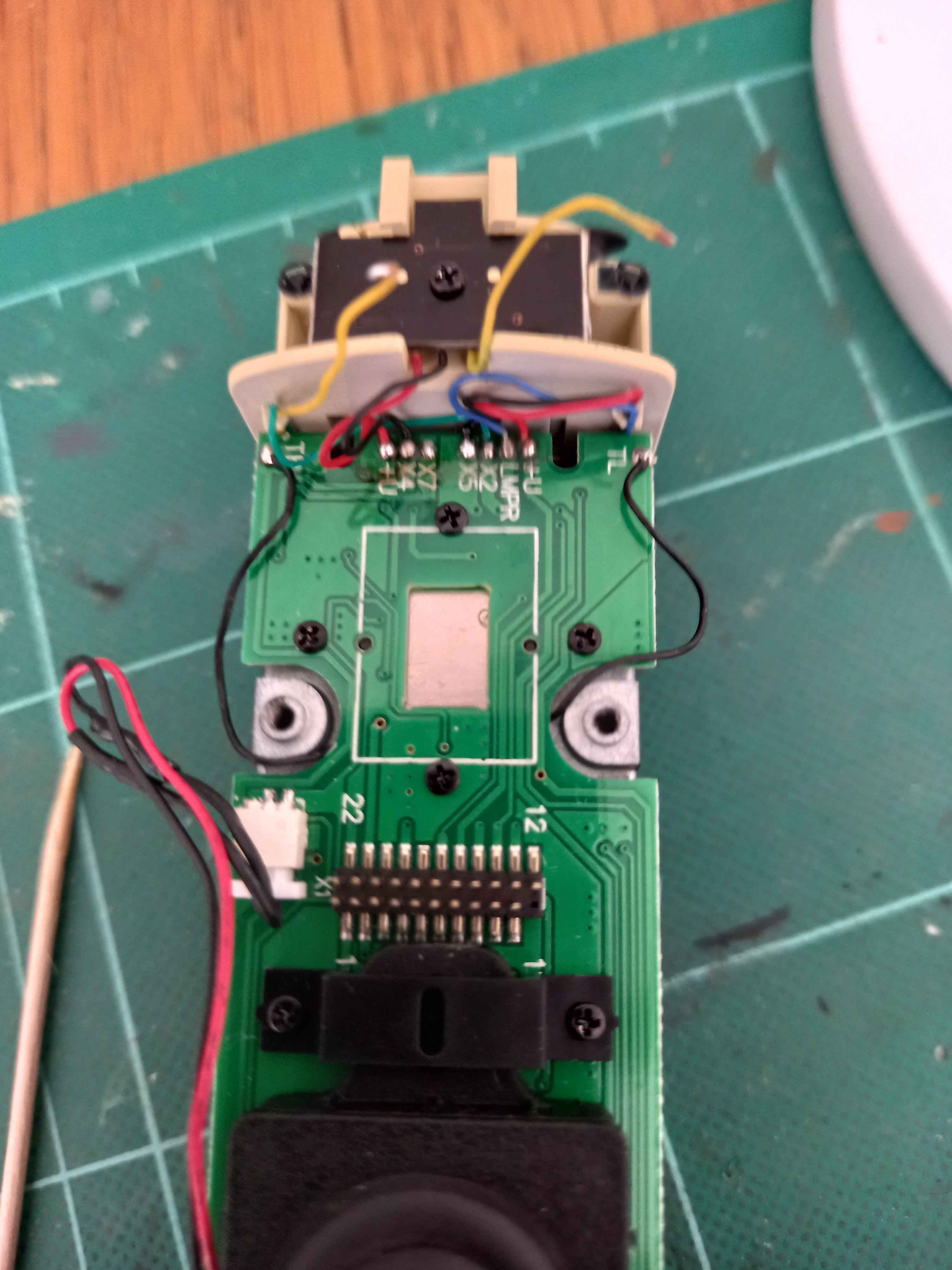
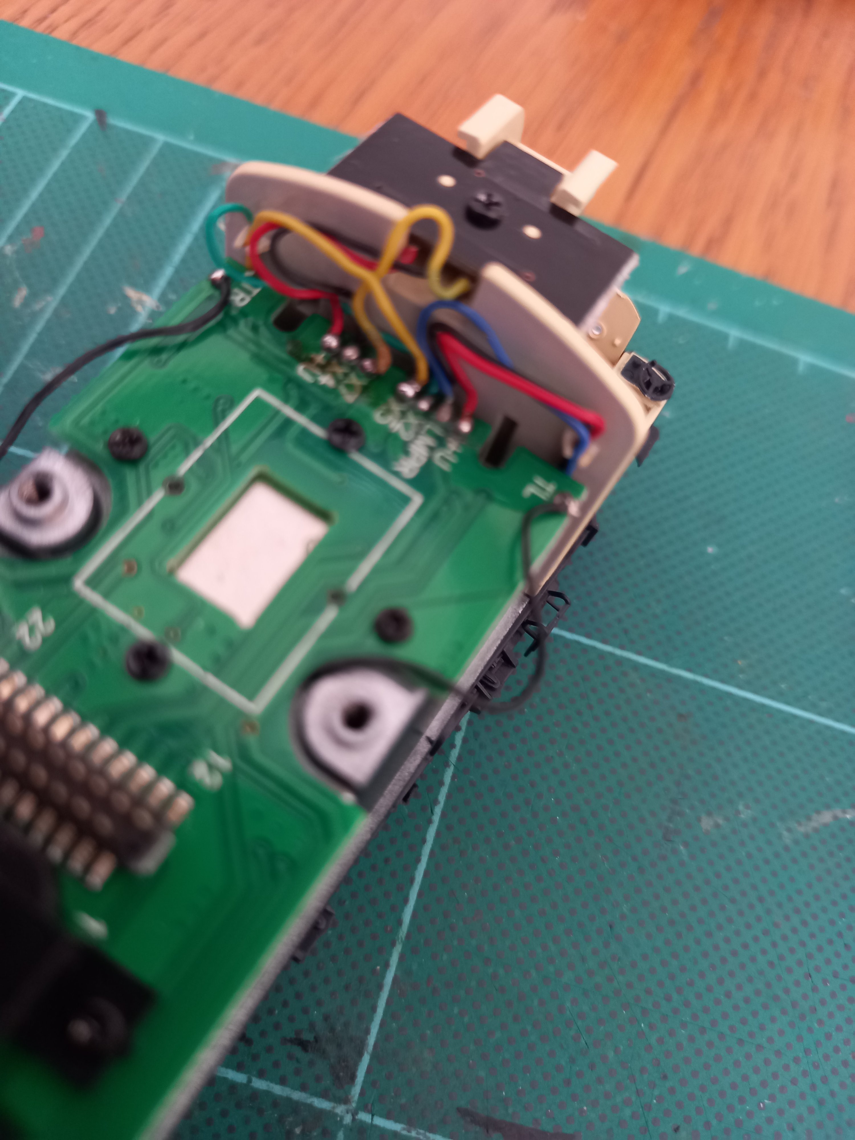
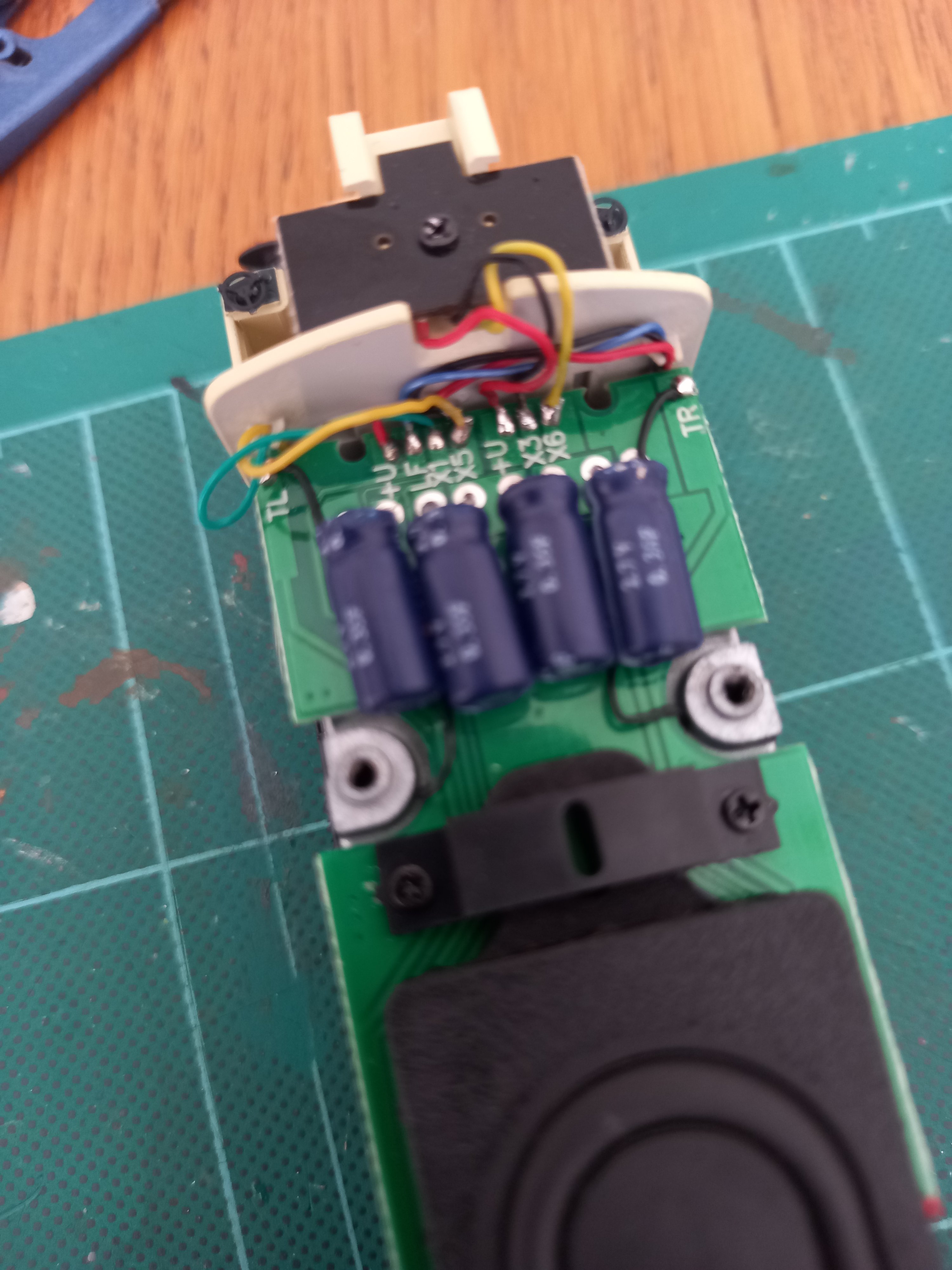
Decoder End : Remove the decoder as that allows a clear area to work in. The cab light wire is set on X5, this needs to be reset on X7. Thread the cocktail stick through X5 wire so you can lift it away when you apply soldering iron to tab, apply a tiny dab of solder to iron before unsoldering X5 wire, be careful as there is a black wire soldered to the same tab underneath. When you have released X5 wire, re tin the wire end. Clean the iron after each step.
You may now need to move other wires out of way to access X7 wire that comes in from side of cab back wall , again use cocktail stick to tension wire and apply tiny dab of solder to iron then release X7 wire from tab. Again re tin X7 wire end.
Apply tiny dab of solder to iron and using tweezers hold X5 wire to X7 solder tab & solder X5 wire to X7 tab. Try to keep tweezers away from tinned wire end as it dissipates heat from iron as wire is very thin.
Same procedure & solder X7 wire to X5 tab.
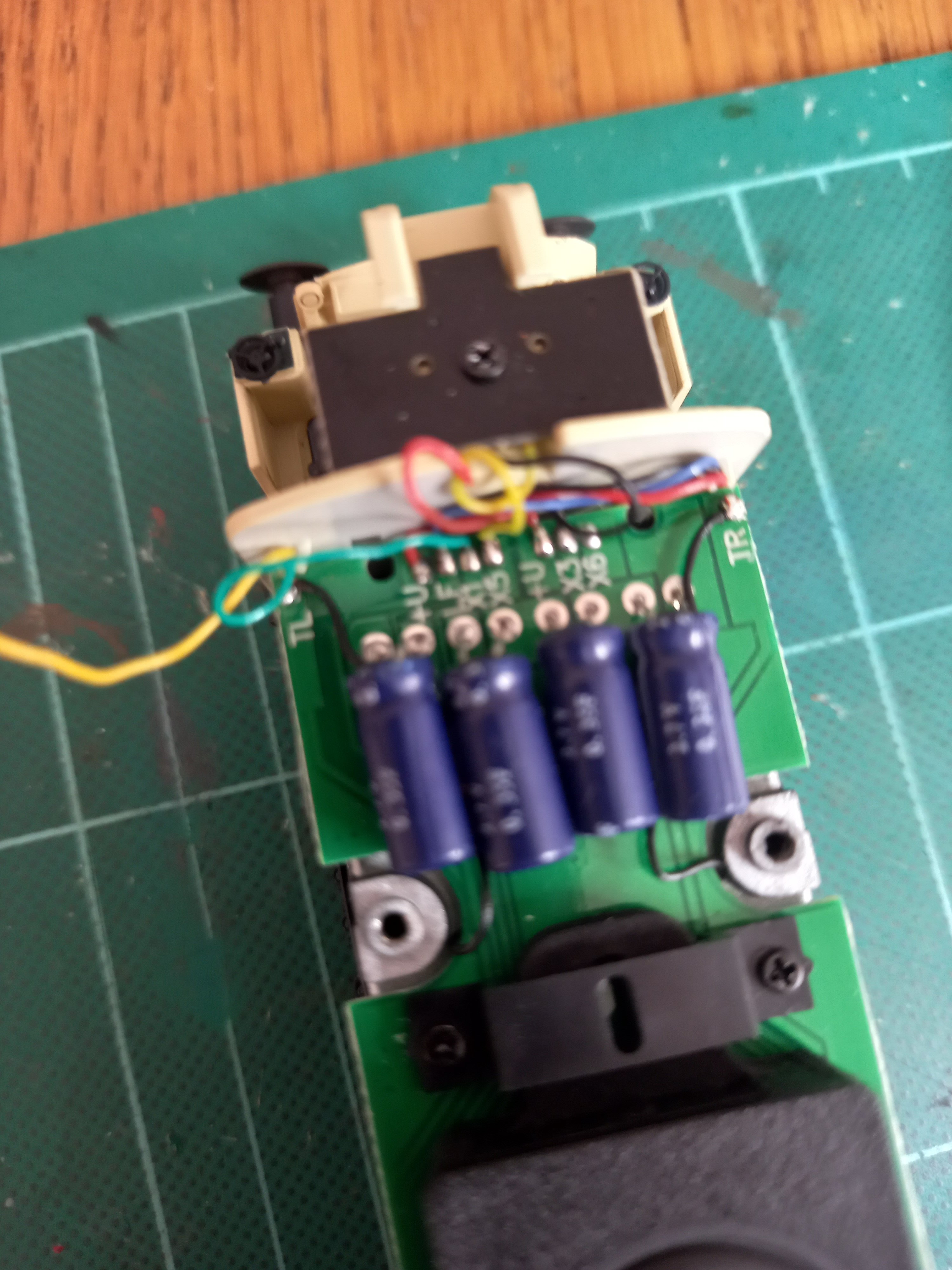
The Capacitor End : Not a lot of space to work in, same procedure as above, except start with releasing X6 first and then X5. The cab light wire is X5, again there is a black wire soldered underneath to X5 tab. If you are unlucky enough to release black wire resolder it back before doing anything else and give it time to cool, hence only tiny dab of solder to iron. The other wire is X6. Same procedure as before. X5 wire then goes to X6 solder tab & X6 wire goes to X5 solder tab. Using metal tweezers dissipates the heat from the iron through the wire as the wires are very thin. Try to hold the tweezers as far away from iron/solder tab as possible. Don't forget to clean iron after each step. You will see from photos other pcb wires moved out of way, you do not want to touch any wire cover with iron as the cover will melt instantly.
Apologies, the first photo is a little blurry, it shows the wires ex factory.
The last 2 photos show the iron, flux & solder I use.
Good luck & feel free to ask any question.
-
1
-
3
-
-
12 minutes ago, Noel said:14 minutes ago, Noel said:
Is there a published fix for the cab lighting, or how to do this on the IRM support site?
There is a video on YouTube, but I can’t remember where, it was mentioned on here but again I can’t remember where.
I have some photos on my phone that I will post with an explanation of what to do. I’m on IPad just now.
-
A46 sorted at last. Rewired for directional cab lighting, Crossley Sound, drivers and Kadees fitted.
Video is a bit stop n start, be patient.
-
2
-
-
Picked up a Heljan TT for £250 from Rails Sheffield. Looking forward to turning 121 loco’s on it.
-
1
-
-
Noel, did you manage to remove the bogies and what make did you replace them with ?


IRM Working Tail Lights.
in Irish Models
Posted
Looks interesting. And not expensive !