

Richard EH
-
Posts
163 -
Joined
-
Last visited
Content Type
Profiles
Forums
Resource Library
Events
Gallery
Blogs
Store
Community Map
Posts posted by Richard EH
-
-
Very much looking forward to this one!
Richard.
-
Hi all,
Happy New Year to all on the forum!
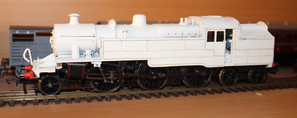
Managed some progress on the WT over Christmas in between all the celebrations and mince pies!
Really all I've now done is completed the riveting on the side tanks using the archer resin rivets. As mentioned previously, I've used the sample pack to get the various spacing of rivets. The tricky bit was getting the corners right and I've generally cut each rivet out and applied them individually. Done a few at a time and then applied some matt varnish to make sure the next set didn't lift the previous set... was straightforward but was time consuming...!
Next step is to sort the cab steps, cab rainstrip, relocate the whistle, and sort some steps for the back of the bunker. That'll sort the body I think ready for painting and after that it's about looking at some replacement wheels as helpfully set out upthread.
All the best for now.
Richard.

-
ooooh yes.That's good, so very good!!
Very well done!
Kind Regards
Richard.
-
And as a postscript, I hope they can do some good quality lining on the u for the price.... That'll be tricky having tried it myself!
Richard
-
This is a great development, and although pricy, is one I look forward to supporting.....
A u/ug cuts down on development time and therefore cost as the tender, cab, boiler and smoke box are the same... So you get two for most of the development costs of one....
Richard
-
Hi all,
Many thanks for the kind comments. progress stopped for a while whilst I awaited a new tin of testors dullcote: until I could put a quick blow of varnish over it, I couldn't make progress with the rivet detail. That's now arrived and by coincidence it's currently drying as I've pretty much finished the left hand side, rear bunker and have made a start on the right hand side.
Will post up a photo or two when the rivets are done. Just a bit of detailing I think then, cab steps and maybe relocate the whistle. Thanks for the clues on the driving wheels, will take a look at those and see what I can get hold of.
Richard.
-
They do look good. You get what you pay for and of course, you don't have to buy them....I'll keep an eye on their website and see if anything of interest for me emerges.
Kind Regards
Richard.
-
Many thanks for the kind comments all, that's much appreciated!
I've done some experimenting, and what seems to work for the curved section of rivets is to:
1. cut out a line of rivets
2. cut into individual rivets on the cutting mat
3. then move into a small puddle of water on the cutting mat so that the water is soaked up
4. pick up with the knife when loose and apply carefully
5. Repeat.... a lot!!
Gonna be here a while....! Will update when I've some pore progress to report....!
Cheers for now
Richard.
-
Looks good Richard. PS can you answer your PM please?
Apologies, PM sent!
Richard.
-
oh well! Another cunning plan, dashed!! Clearly you've looked into it in some detail=D
Kind Regards
Richard.
Hi Richard,Unfortunately they are quite different designs...
Thanks for the order.
-
Had a closer look and the hopper does seem very similar, the axles/supports look more modern, not a surprise I guess...
oh, and order placed as well, good luck with the project!
Richard.
-
Hi guys,
The hopper looks very similar to the GRNi one as well as shown in the oakwood press book - not sure if they share the same design, but there may be an additional opportunity for a model if they are the same! (and one which would appeal to steam era modellers as well.....)
Kind Regards
Richard.
-
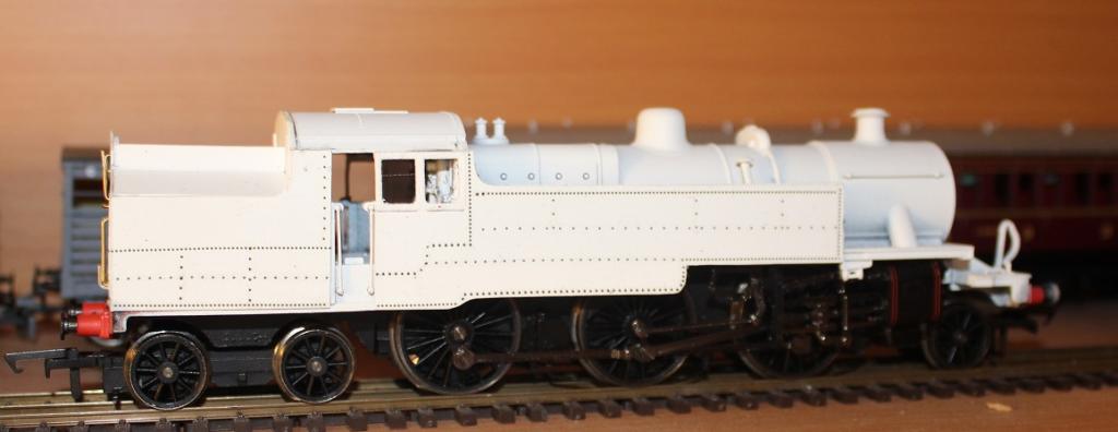
Hi all,
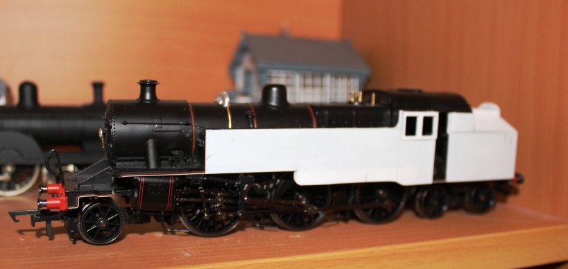
Quick update as I've progressed a bit further. I've shortened the cab at the rear and replaced the rear spectacle plates with a new plasticard back to the cab. I've also completed the platework on the bunker - though it needs a bit more work at the back of the cab.
The main bit of progress is a quick blow over with some white primer, and I've started to add the archer resin rivets. The pack I've bought was the demo pack with a variety of rivets per centimetre, so I've been poring over some of the good side on shots of these machines to get the right look to the multiple rows of rivets. The main problem with these is that all of the rows are in straight lines, so I'm mulling over how to apply the rivets on the few curved sections on the tank. I think the best way will be to cut individual rivets out on their strip, soak on the workbench then pick up with the knife and apply gently....I've already put a thin coat of dullcote on so the existing rivets won't be going anywhere...
Final bit of progress is the handrails going onto the rear of the bunker.
Anyhow, looking good for now,
Cheers for now!
Richard -
This is a fantastic development, well done!
Not quite my era.... but, ok, I'll go for a set I think!
Richard.
-
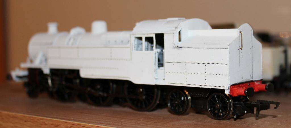
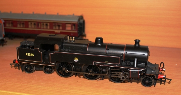
So I’ve been giving the WT some thought and went to expo em the other weekend.
I’ve decided to take option B and shorten the cab on what is, by using a fowler tank as a base, not a 100% WT clearly! I do wonder if the loading gauge is slightly bigger compared to the fowler tank as it just seems a bit… fatter… all round.
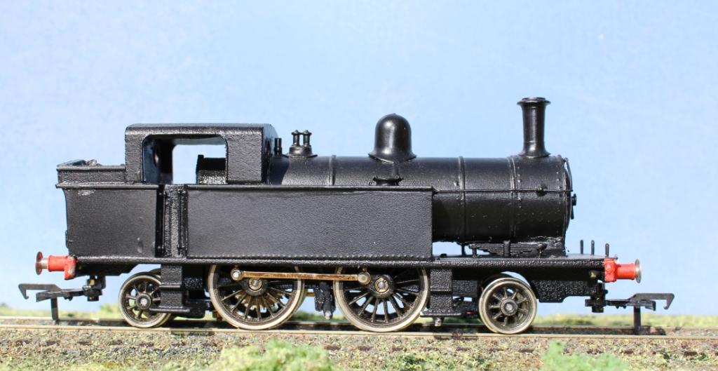
In any case, the photo shows the chopped cab in profile which I think looks pretty good. Certainly matching it with some of the side on shots in ‘parting shot’ seems to give something which doesn’t cause any problems for me and I think looks the part.
I was wandering round Expo em to search for some etched rear cab spectacle plates but there didn’t appear to be anything suitable, so the next step is to make something suitable up in plasticard, remake the top of the bunker behind the cab after the razor saw has been at it and make good. After that, lots of fun with rivets beckons for the tank sides, and some scrap etch for the cab steps.
Cheers for now.
Richard.
-
Looking good!
You're right about the cab being too long. It's also too far back - the GA drawing appears accurate in this respect. Ideally the cab needs cut free, moved forward a little and a bigger slice taken vertically out of the rear. I think the front and rear cab sheets fold up from the floor unit which latter can be trimmed accordingly and the rear, then re-attached. Just cutting away some of the excess length at the back will make a difference (you may want to increase the width of the top, open section of the coal bunker, at the same time, to improve the cross-section). But leaving the cab front where it is, means the cab front, the last step in the side tanks and the rear driving wheel centres don't line up right, in profile view.
I would definitely suggest trimming away the little 'skirt' under the footplate/running board all the way along, rather than taking the new plasticard tank sides all the way down to it. It's not that deep, but it's enough to make the big side tanks look too deep, at the front - all the way along, in fact. It'll leave a little gap above the cylinders, unless you can move them up a little, but better that, than deepening/distorting the outline of those distinctive side tanks.
May seem like a lot of bother for comparatively little return but you are already doing a fairly major conversion job and might as well make those few extra cuts that will make all the difference to the accuracy of the finished model, rather than (as I have done in the past!) hold back, thinking 'It'll be near enough!', then wishing after I done all the painting and finishing that I had gone a bit further!
Many thanks for the details there, I'll mull over and think through a way forward - three options, I think:
1. Stick with the cab as is:
2. Shorten in the same place:
3. Shorten and move forward.....
All of which have their pros and cons - and as it's a fowler tank anyway, some compromise is inevitable....
Cheers for now.
Richard.
-
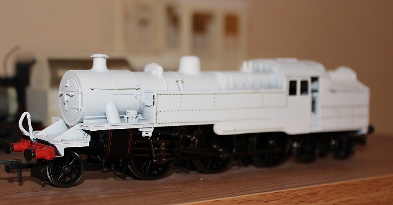
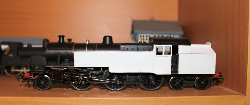
A quick update on progress since my first update.
I’ve fitted the piping into the new whitemetal top feed which I think looks the part.I’ve also now added the 3rd printed window frames on one side. I’ve used both on one side as they were a bit thin – I’ll need another pair for the other side – but it will allow me to fix some glazing for the cab side window and then a little bit of glue to stick the remaining fame over the top which should make a nice clean job of this part of the cab.
Also now added are plasticard overlays to the tank and bunker sides. This has allowed a clear view of how it looks without being distracted by the BR lining, number and crest. What seems clear is that the rear section of the cab is too long and it needs to be shorter. I need to use caution here clearly as the cab roof is a clearly visible part so it’ll be some careful work with the razor saw, I’m not too concerned with the loss of the rivet detail(see below), but it will need to be a precise job. The additional benefit is that it will allow me to get the rear cab windows the right shape so I’m on the lookout for some suitable etches for these and the protective bars over the windows.
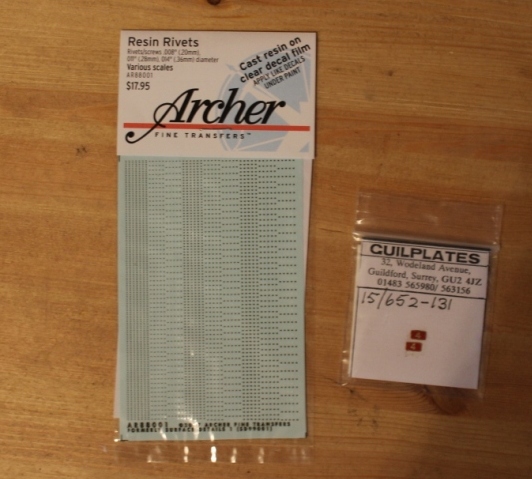
I’ve also now received the sample pack of archer rivets – picture attached. These look like they’ll be great and I’ll be able to carefully mark up the lines for the rivets on the white plasticard sides and then cut out an appropriate length. The tricky bit is likely to be the curved sections on the base of the tanks – but I think tha just needs a bit of care. Also now received are the set of numberplates from guilplates, and very nice they look too!
Just need to order a set of window frames and I’ll have all the parts I need to complete. Not as quick a job as I was expecting but coming together well.
Cheers for now.
Richard.
-
Well, you can buy the body here: http://www.shapeways.com/product/322AX6GR7/4mm-scale-gnri-jt-tank-body-shell-16-5mm-gauge?li=search-results-1&optionId=8347275 and frames here: http://www.shapeways.com/product/UREBHFRZB/4mm-scale-gnri-jt-class-2-4-2-tank-chassis?li=search-results-1&optionId=7571758
But bear in mind the side tanks are plasticard overlays, the owner has explained how he gets such a good result but I can't find the post.
The JT is one of mine, and it does indeed use a lot of plasticard to get a smooth surface on the side tanks - one of the reasons for this is that I tend to use the Shapeways WSF material for cost reasons....
Kind Regards
Richard.
-
Hi guys,
Many thanks for the words of encouragement.
I should say the 3d windows are 3d window frames, all window glazing on the side windows will be conventional clear plasticard if required! The drawing is the one on the forums resources, however, as I'm working from the hornby fowler tank anyway - it's following the principle of if it looks right, it is right.....!
I've now received the archer transfer pack, and they look rather nice. The guilplates numberplates have also now arrived and look good too, so once the window, frames, arrive, I'll have all I need to proceed - I'll be sure to post some updates as it develops!
-
Hi all,
First post in a while, but that doesn’t mean that I’ve not been building, just that I’ve not had time to write some stuff up!
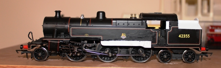
So a long time loco on my wish list is a WT 2-6-4 tank. I’ve read a lot of the good work others have done on this forum, and in New Irish Lines over the years, and decided that I’d give it a go as a quick conversion (Why does that always turn out not to be the case!). Managed to pick up a nearly new Hornby Fowler tank - the new version with finer valve gear and detailing to use as a basis for about £50. S and J models in Northwich was the source for this, and started mulling over the plan to get it as good as I can, and to use as much of the good detail work that this model possesses.
First action was to print off the drawing in the resources section of this website, which correctly has the double drop on the side tanks – I’ve seen another drawing which doesn’t have this, and to work out what to remove, and what to keep. So, to remove, I decided on the following:
• Bottom section of the tanks
• The radius on the running plate above the cylinders
• Cab side sheet(to insert the side windows)
• Smokebox clips
• Rear bunker behind the cab(retaining the middle of the moulded coal to retain the fixing screw
• Rear bunker detail
• Cab steps
All of this was done with careful work with a razor saw for the bunker and side tanks, scalpel for the minor detail and drill/scalpel to remove material from round the cab side sheet. The plastic this model is made from cuts and glues very well – it’s a dream to work with.
To add:
• New section of the side tanks from plasticard
• Top feed on the boiler (from spares box) and pipework form brass wire
• Smokebox wheel (made from a 16ba bolt, brass wire and a washer soldered up and filed down)
• New bunker (from plasticard
• New cab windows (3d printed – on order)
• Numberplates (on order from Guilplates, decided to go for No.4 so I’ve plenty of time periods to run it from the 40’s to present day
• Rivets on the side tanks (I’ve a set of the resin rivet sheets on order from Archer in the USA which should do very nicely.
• Various handrails/steps/lamp brackets etc( to add from brass wire, etc)
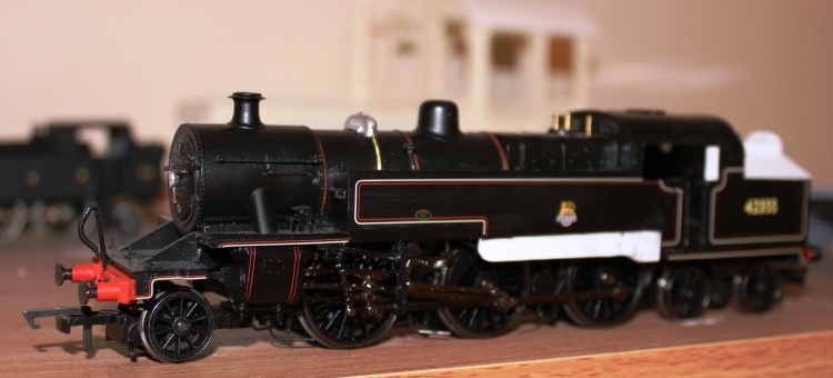
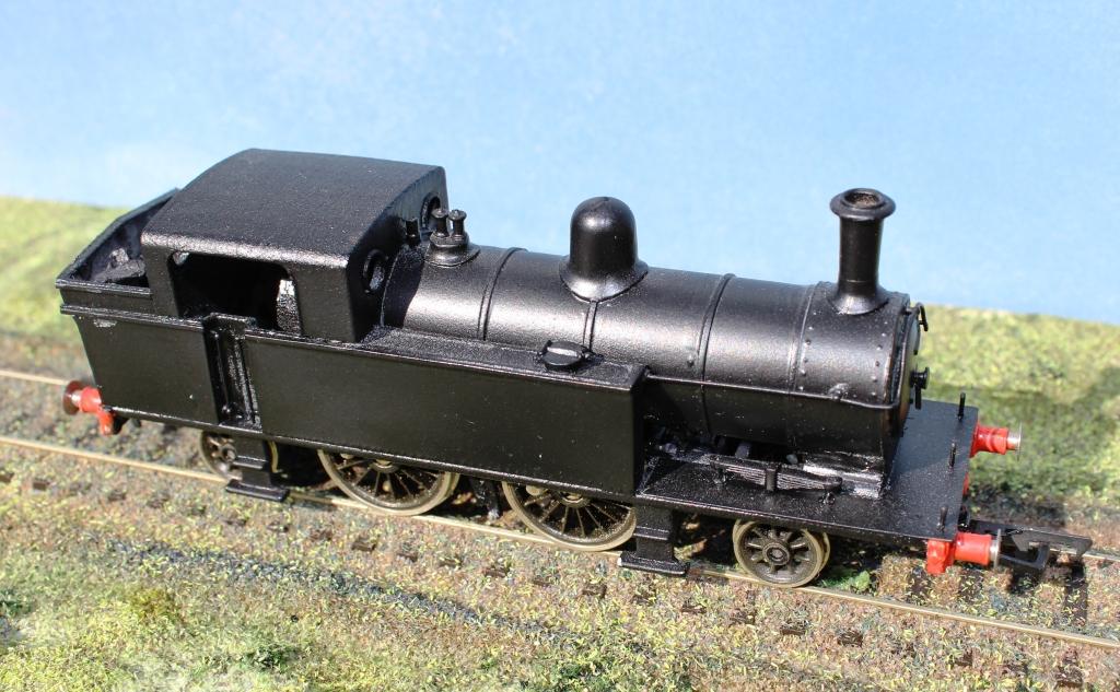
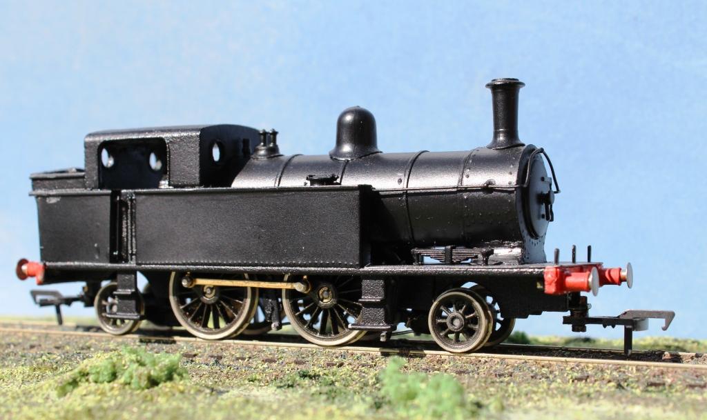
Please find below a few photos illustrating where it’s currently up to. It’s quite a straightforward conversion really – the only bit that really isn’t quite right is the rear section of the cab which is a few millimetres too deep but seeing as it’s the wrong gauge anyway, I’m not too worried….
I’ll add some photos as this develops, but it may be a while before I do!
-
I've just received one of these GNRi Gardner buses and I have to say, to my mind - it's a lovely resin kit! Well recommended if you're thinking of taking the plunge and ordering one! Very nice set of transfers included as well.
Regards
Richard.
-
Thanks for the kind comments guys! I'll post up some photos of 93 in the next week or so.
Regards
Richard.
-
]Hi David,
Thanks for that!
No, the boiler is a plasticard overlay, and the bands are plastic strip overlaid on top.
My website has further details :http://www.glr3dmodeldesign.co.uk
Attached are a couple more photos taken at the weekend, wonderful light on sunday, always nice to get in the garden and get some nice natural light photos!
Regards
Richard.
[ATTACH=CONFIG]13818[/ATTACH -
Given the interest on another thread in my 3d printed JT tank, I thought I’d start a specific thread detailing the approach to creating this model.
I should say at the outset that it is available to buy, if you’re interested – however, I know there are diverging views on the suitability of 3d printing, currently, for modelling. I think I’ve found a way here which makes the best of the technology, and mitigates some of the problems – surface texture being the key one. I have to say there doesn’t seem to be much demand for it, however I could do with a couple at least for my own layout – I plan to model Ballyhaise at some point…. So clearly it’ll be a great loco for me to model.
This project was actually started around 3 years ago. I wanted a JT tank, and having the opportunity of some time whilst ‘between jobs’ I taught myself how to use google sketchup. At the time, I couldn’t find a proper set of drawings for the JT, only outline side elevations in a couple of books – plenty of pictures though of them in their final years on the Belturbet branch. Clearly, there’s a preserved one, and Mark Kennedy kindly took a tape measure to it, to provide an overall width – most helpful!
Supplied with that information was enough to draw it up. <Photo>. Given that it is quite a simple 2-4-2 tank, I split the frames so that the driving wheels are supported on quite a thick short chassis for strength which is printed in White Detail which is very rigid and works well so long as it’s thick enough – it can be a bit brittle so thickness here is essential. I designed in some holes for supporting the brake gear, and a between wheel bracket to support the pick ups <Photo>.
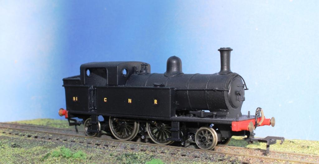
The front and rear fames, both bogies and chassis are printed in white strong and flexible, which gives reasonable support, wall thickness and is relatively cheap. I designed the body to omit the smokebox, chimney, dome, whistle etc – these are all best done, certainly in my view, by using existing brass or whitemetal castings. To get around the texture issue, which I don’t find a huge problem (it’s all in the finishing – see below), I clad the running plate, bunker sides, boiler and smokebox in 10 thou plasticard embossed with rivet detail. It’s not easy or really possible to do the curve of the cab roof so I’ve lived with that.
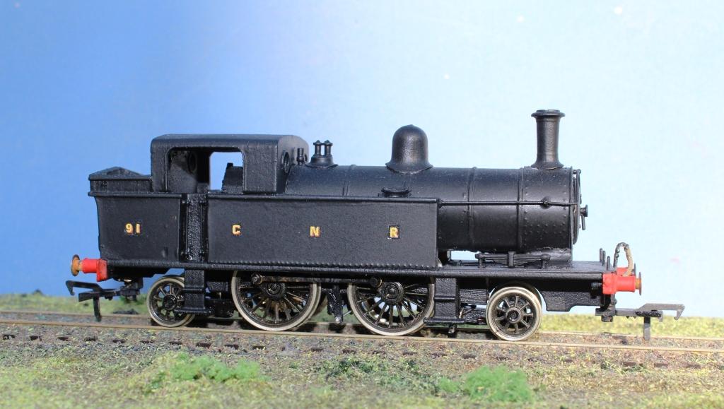
The final piece of 3d printed detail is the most interesting one – these are the 3d printed brass connecting rods. Given that it’s my own chassis and wheelbase that I was using, I drew up the two rods, joined them with a sprue and printed them via imaterialise in brass. I’ve bushed them, and they’re fitted onto standard Romford wheels and crankpins. So far, they’ve proved robust.
The build was quite straightforward really, detail the body with the plasticard, add the chimney etc. For the chassis, I used a mashima motor and a branchlines 40:1 gearbox. Romford wheels and crankpins. The brakes are alan Gibson plastic parts with wire for the brake rigging.
The finishing was interesting, a blast of Halfords car primer, and the secret with the WSF is to give it a good scrub with a toothbrush and water to remove any loose bits and get it as smooth as possible before the final coats are applied. I managed to source some transfers from <<>>> but then when I applied the varnish, found that it had got cold and when sprayed on resulted in a snow like appearance. Luckily a wash and partial repaint meant it was rescued, so 91 is now ready for service.
93 isn’t far behind now!
Anyhow, I hope that is of interest, and gives some background to the build process. I can post more on the 3d printed GNRi passenger brake vans if there is interest.
Regards
Richard.
-
 1
1
-


4mm scale 'WT' rebuild from a Fowler 2-6-4T
in Irish Models
Posted
Hi Guys,
Many thanks for those kind words, will keep the thread updated with progress.
Kind Regards
Richard.