wiggy Posted March 17, 2013 Posted March 17, 2013 (edited) Anyone converted a Silverfox NIR 106 from DC to DCC.? Not sure what the donor loco is, either a class 22,29 or 73 but I think they are all the same. I've removed the non driving pickup bogie and there's 2 wires coming from it so obversely it picks up from both tracks. I've removed the driving bogie and there is one wire from the axle pickup on one side. This pickup wire then goes back towards the rear of the loco. I am assuming that there is a circuit board in the body that my have been used to work a head lighting board.(yes can see it when I pull the wires) Then from the rear of the loco comes another 3 wires. 2 go to a capacitor and the other goes to a axle pickup on the motor bogie which is a bit strange as that side of the axle has traction tyres on. All wires are Black so no help there. I've taken some photo's to help. Anyone done one.? Might end up cutting the wires and pulling out the circuit board to see what it dose unless anyone has a Hornby class 22,29 or 73 with a body removed. Thanks, Wiggy. Edited March 17, 2013 by wiggy
0 ger711 Posted March 17, 2013 Posted March 17, 2013 Looks like there is a wire from both sides of the Motor Bogie and also the non powered Bogie which are linked up via a small circuit board and fed back to the Motor via the Capacitor. Have a look at this Service Sheet for Class 73 http://www.hornby.com/downloads/locomotive-maintenance-sheets/?page=4. It's the sixth one down. It might take a while to figure out but I don't think there is any lighting wiring. To simplify it, if you joined the wires from Positive side of both bogies to one side of the motor and the same for the Negative wires to the opposite side of the motor, you have in effect 2 wires. They just link them via the circuit board probably to help with DCC. Ger.
0 wiggy Posted March 17, 2013 Author Posted March 17, 2013 Looks like there is a wire from both sides of the Motor Bogie and also the non powered Bogie which are linked up via a small circuit board and fed back to the Motor via the Capacitor. Have a look at this Service Sheet for Class 73 http://www.hornby.com/downloads/locomotive-maintenance-sheets/?page=4. Ger. Thanks Ger, But that looks like a DCC ready loco. If i could find out where the + & - to the motor are then I could try that. I'm not sure but I think the 2 wires that go to the capacitor are the + & - but its that circuit board I'm not sure about. Thanks, Wiggy.
0 Flying Scotsman 4472 Posted March 17, 2013 Posted March 17, 2013 Wiggy call me tomorrow (Monday) and I'll talk you through it
0 wiggy Posted March 18, 2013 Author Posted March 18, 2013 Turns out it's a Hornby class 73 DCC ready so of with the body (fingers crossed) and in with a chip. Ta, Wiggy.
Question
wiggy
Anyone converted a Silverfox NIR 106 from DC to DCC.?
Not sure what the donor loco is, either a class 22,29 or 73 but I think they are all the same.
I've removed the non driving pickup bogie and there's 2 wires coming from it so obversely it picks up from both tracks.
I've removed the driving bogie and there is one wire from the axle pickup on one side.
This pickup wire then goes back towards the rear of the loco.
I am assuming that there is a circuit board in the body that my have been used to work a head lighting board.(yes can see it when I pull the wires)
Then from the rear of the loco comes another 3 wires.
2 go to a capacitor and the other goes to a axle pickup on the motor bogie which is a bit strange as that side of the axle has traction tyres on.
All wires are Black so no help there.
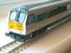
I've taken some photo's to help.
Anyone done one.?
Might end up cutting the wires and pulling out the circuit board to see what it dose unless anyone has a Hornby class 22,29 or 73 with a body removed.
Thanks,
Wiggy.

Edited by wiggy4 answers to this question
Recommended Posts
Create an account or sign in to comment
You need to be a member in order to leave a comment
Create an account
Sign up for a new account in our community. It's easy!
Register a new accountSign in
Already have an account? Sign in here.
Sign In Now