

Fowler4f
-
Posts
288 -
Joined
-
Last visited
Content Type
Profiles
Forums
Resource Library
Events
Gallery
Blogs
Store
Community Map
Posts posted by Fowler4f
-
-
The Key Board Monkey, who at best can only Snipe, whinge & whine.
-
 1
1
-
 1
1
-
-
When taken for a Fool, the Wallet shuts.
-
ZZZZZZZZZZ !
-
The 056s body on the irreparable A46 chassis will sit outside the repair shop awaiting the scrap man’s cutting torch !
-
The sooner the better !
-
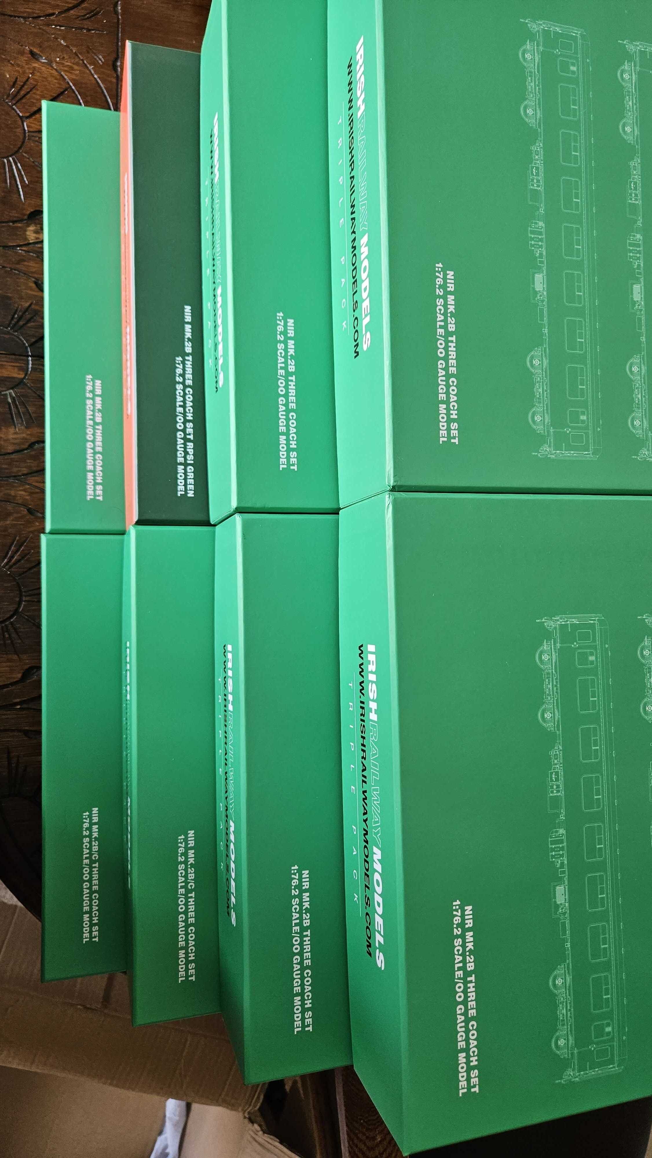
Looking forward to delivery.
-
These lighting control units are a doddle, 12 LED’s per unit and no need for resistors.

-
 1
1
-
-
4 hours ago, BosKonay said:
They’re here !
-
 1
1
-
-
Always remember to wash your hands after handling solder.
-
I should mention that I have rewired all 19 of my A Class locos quite some time ago.
A46 met with an accident recently, breaking off both bogies, the drive shafts & buffers. I purchased a replacement loco 056s from Chris Dyer and swopped A46 body with 056s body, hence the need to rewire the loco.
-
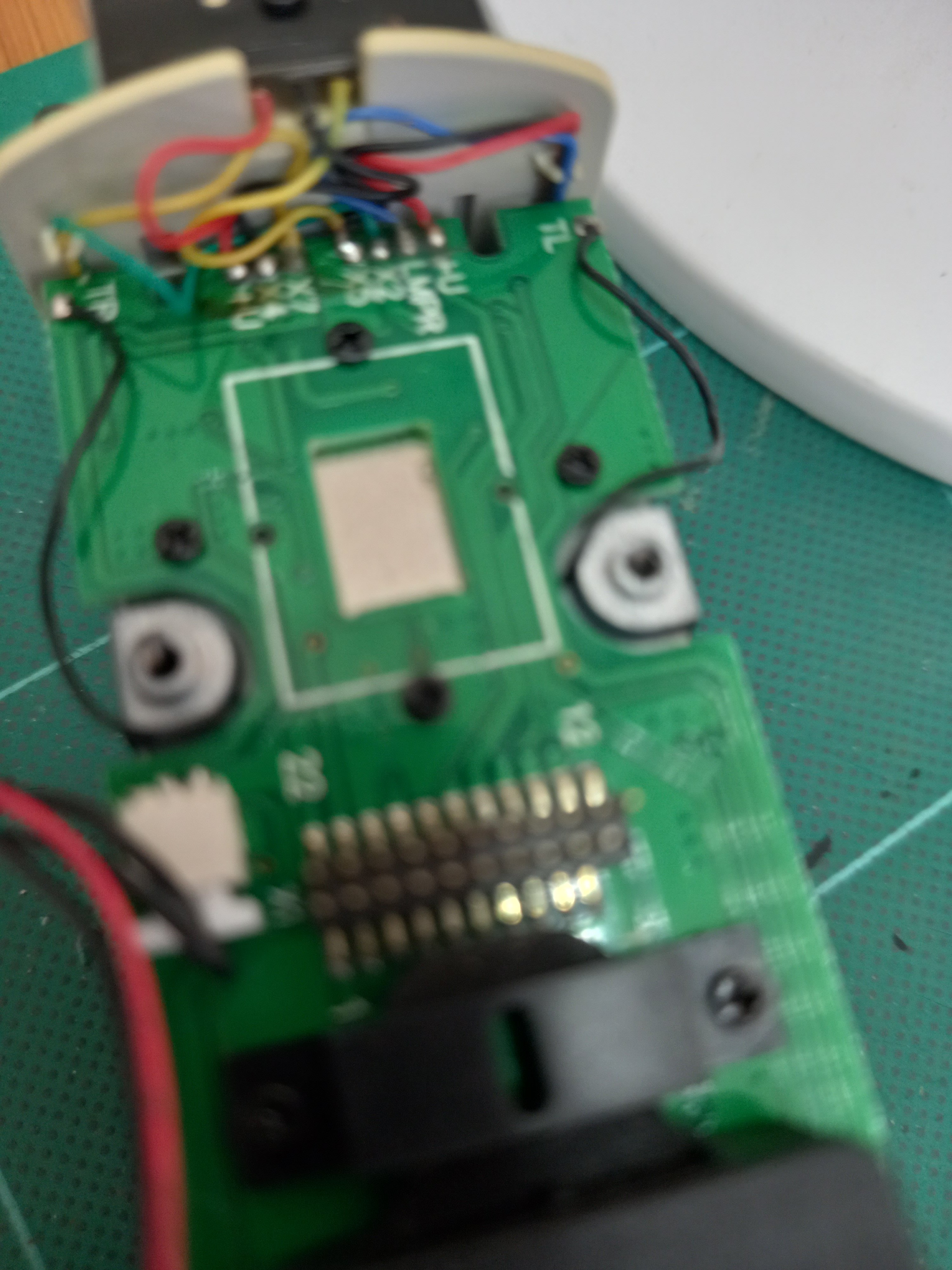
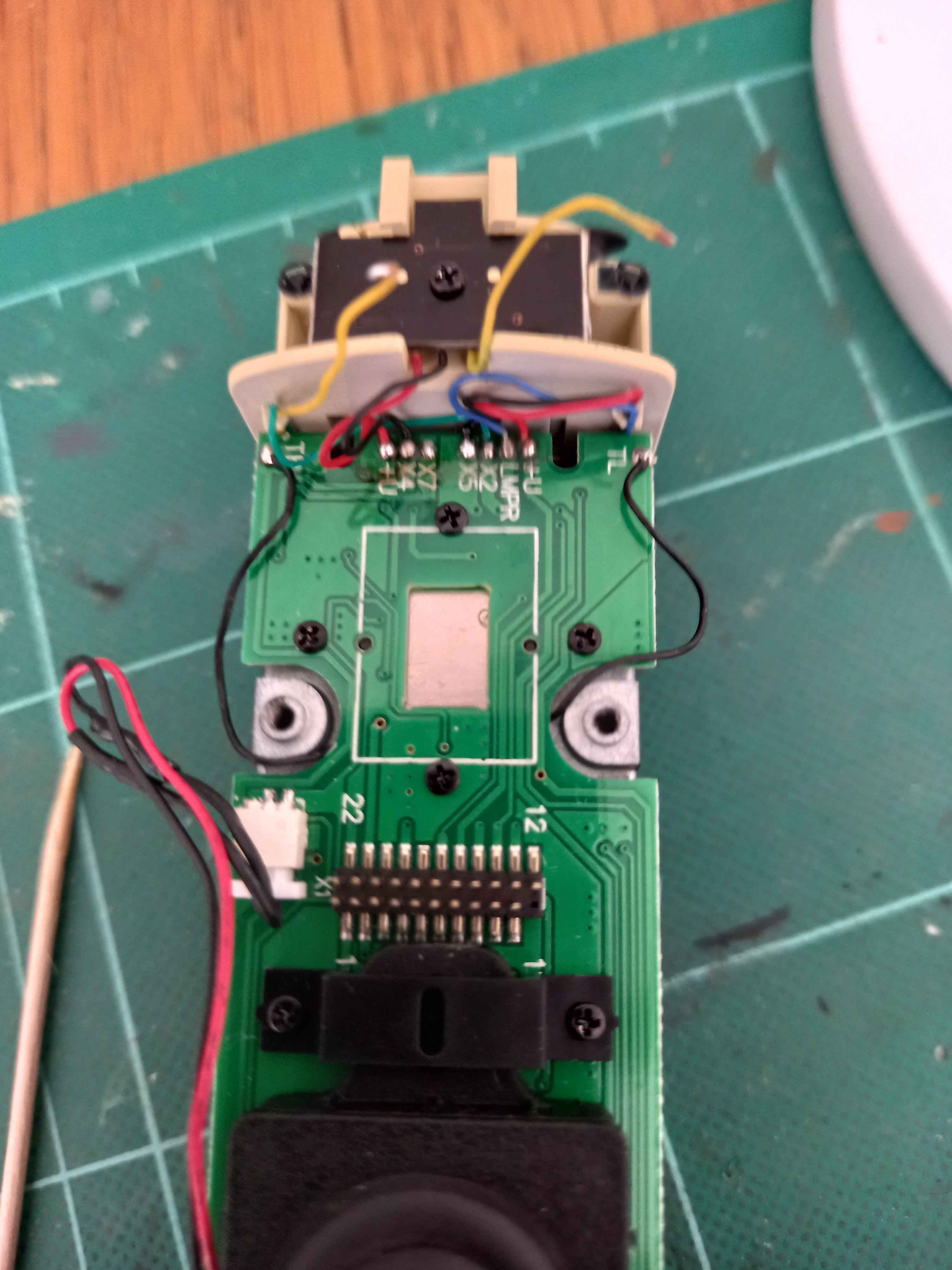
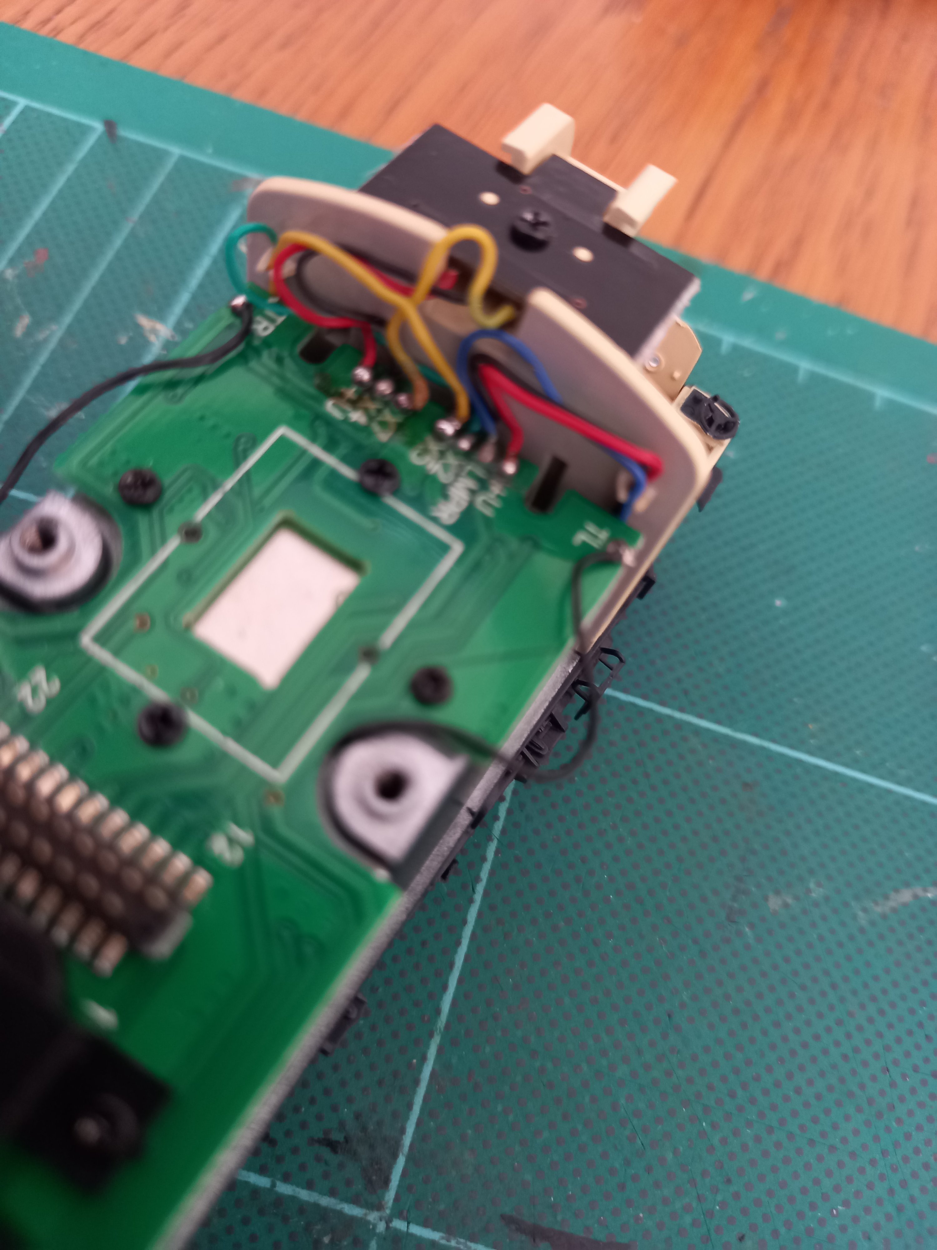
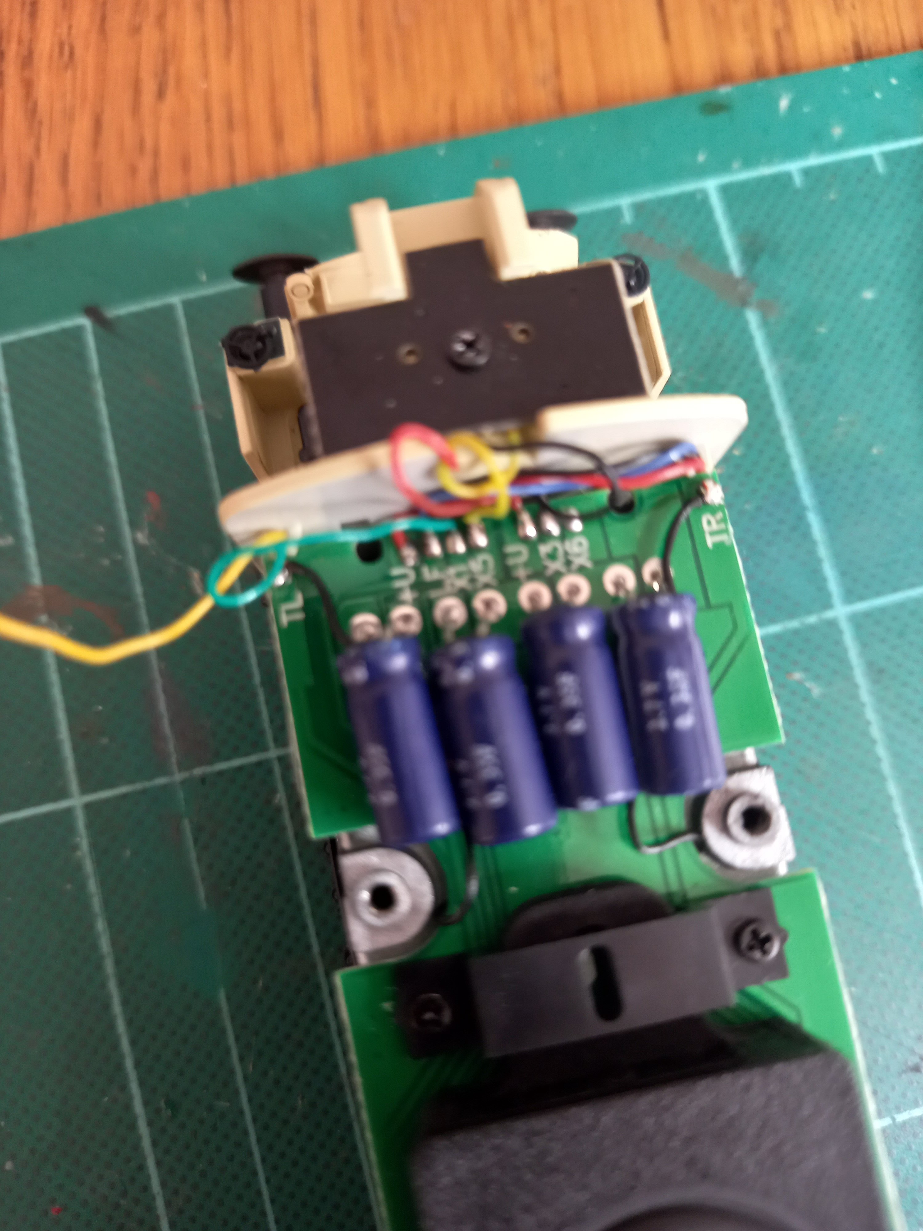
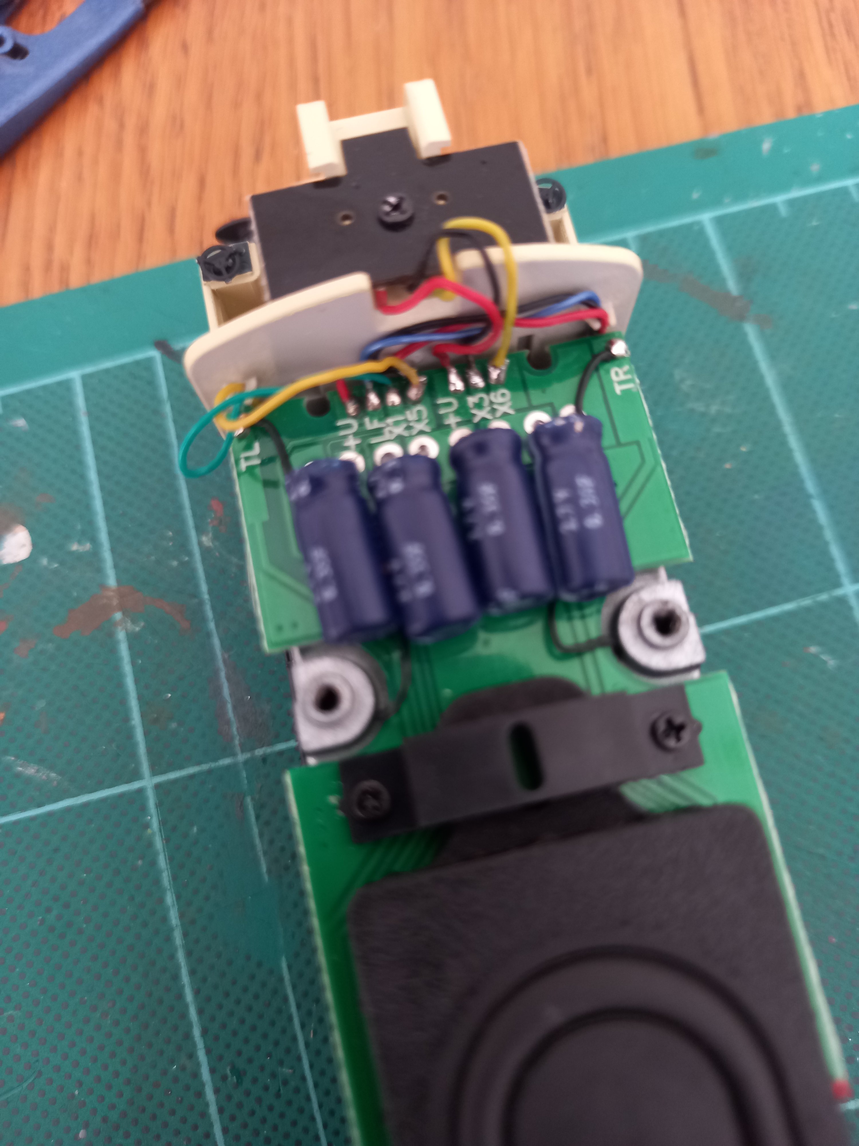
A Class Cab Light Directional Rewire.
All the wires that need swapping over are yellow. 2 wires at decoder end & 2 at stayalive/capacitor end.
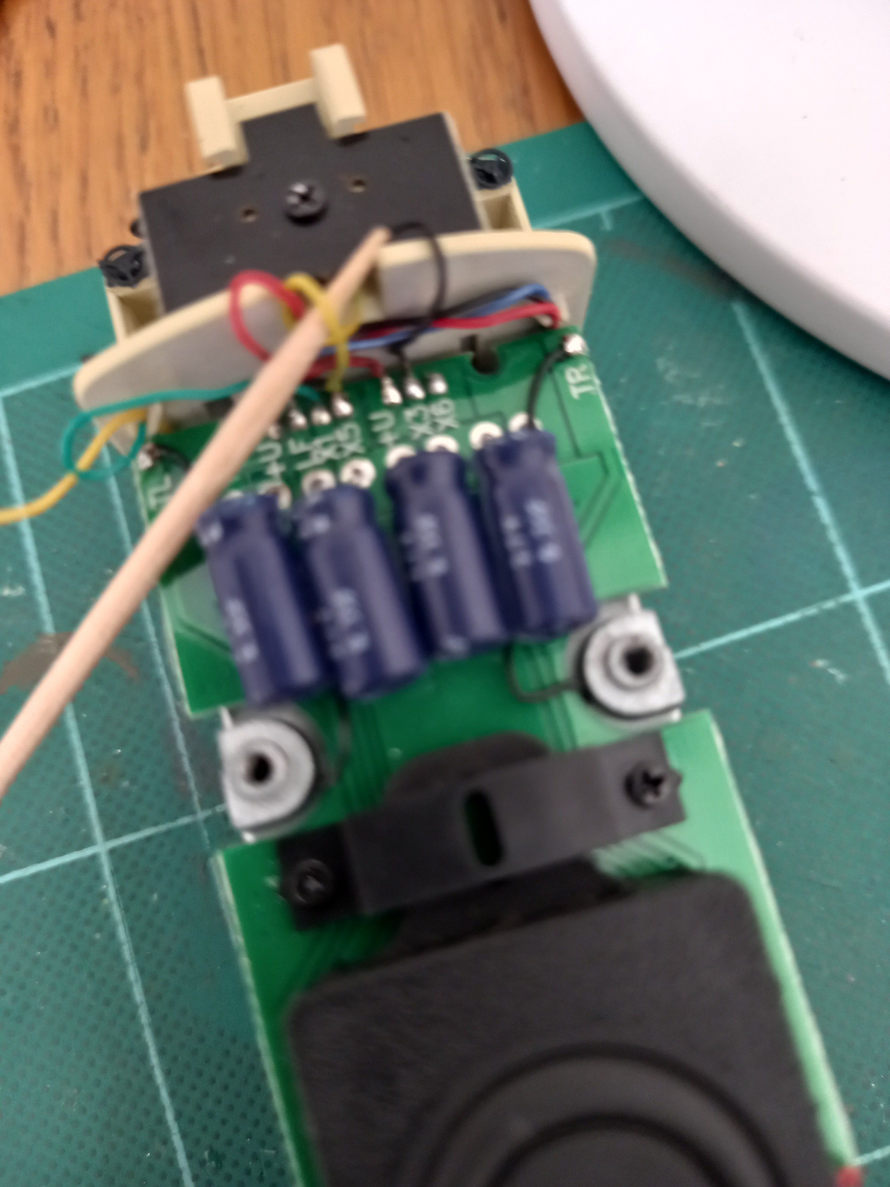
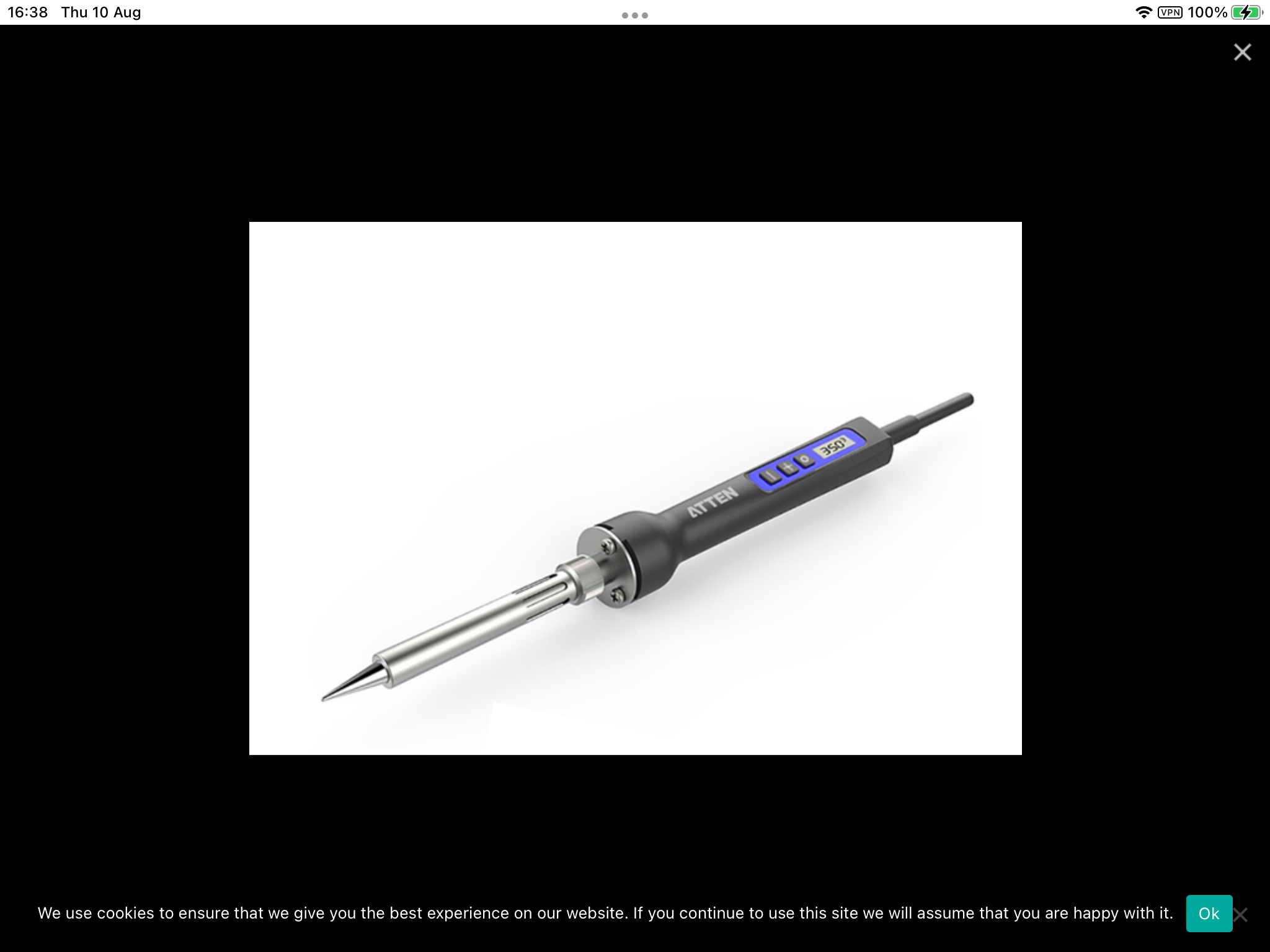
Tools needed : a good soldering iron @ 400° with a clean fine tip, solder & flux, a pair of fine nosed tweezers and a cocktail stick.
Decoder End : Remove the decoder as that allows a clear area to work in. The cab light wire is set on X5, this needs to be reset on X7. Thread the cocktail stick through X5 wire so you can lift it away when you apply soldering iron to tab, apply a tiny dab of solder to iron before unsoldering X5 wire, be careful as there is a black wire soldered to the same tab underneath. When you have released X5 wire, re tin the wire end. Clean the iron after each step.
You may now need to move other wires out of way to access X7 wire that comes in from side of cab back wall , again use cocktail stick to tension wire and apply tiny dab of solder to iron then release X7 wire from tab. Again re tin X7 wire end.
Apply tiny dab of solder to iron and using tweezers hold X5 wire to X7 solder tab & solder X5 wire to X7 tab. Try to keep tweezers away from tinned wire end as it dissipates heat from iron as wire is very thin.
Same procedure & solder X7 wire to X5 tab.
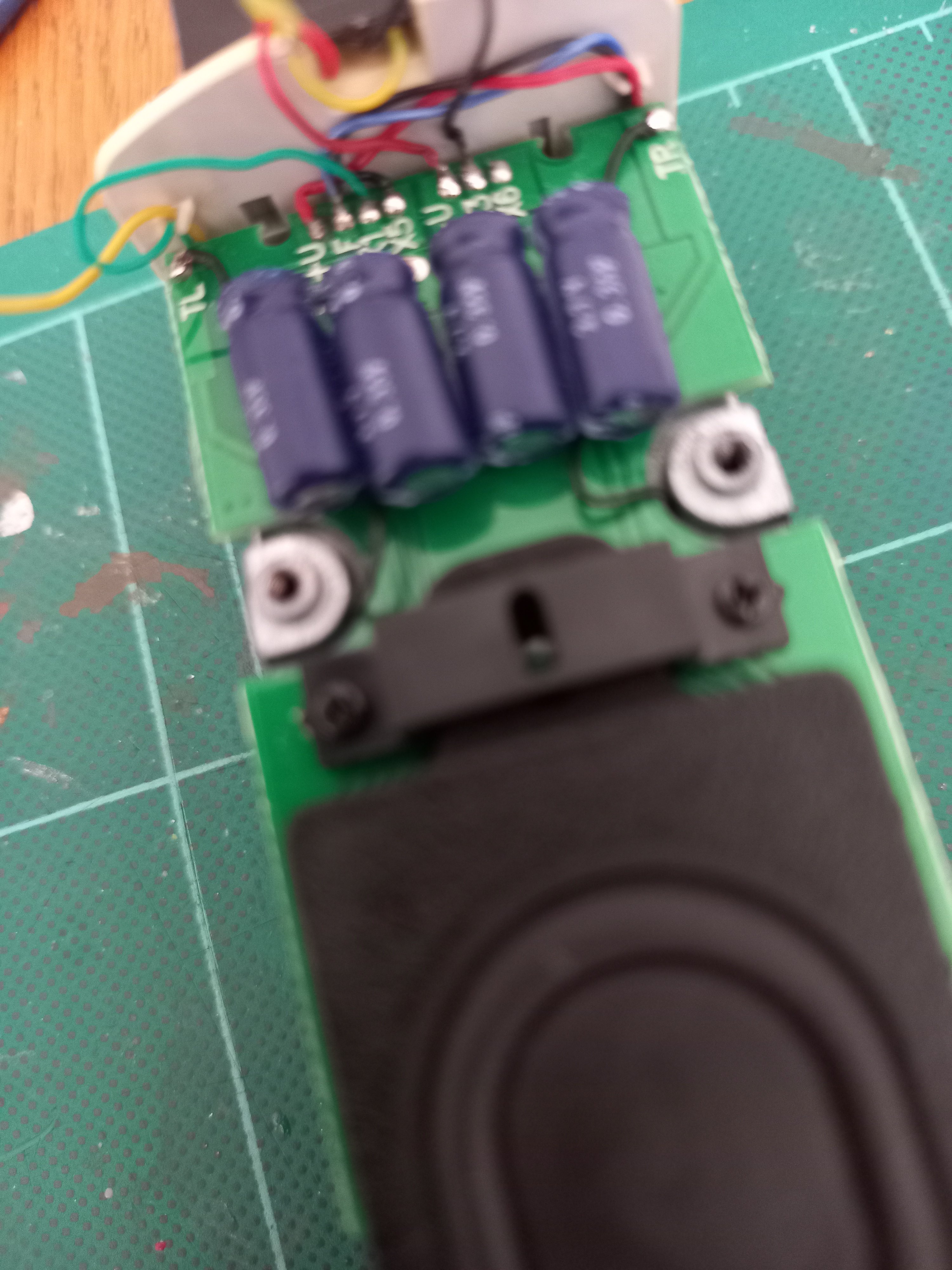
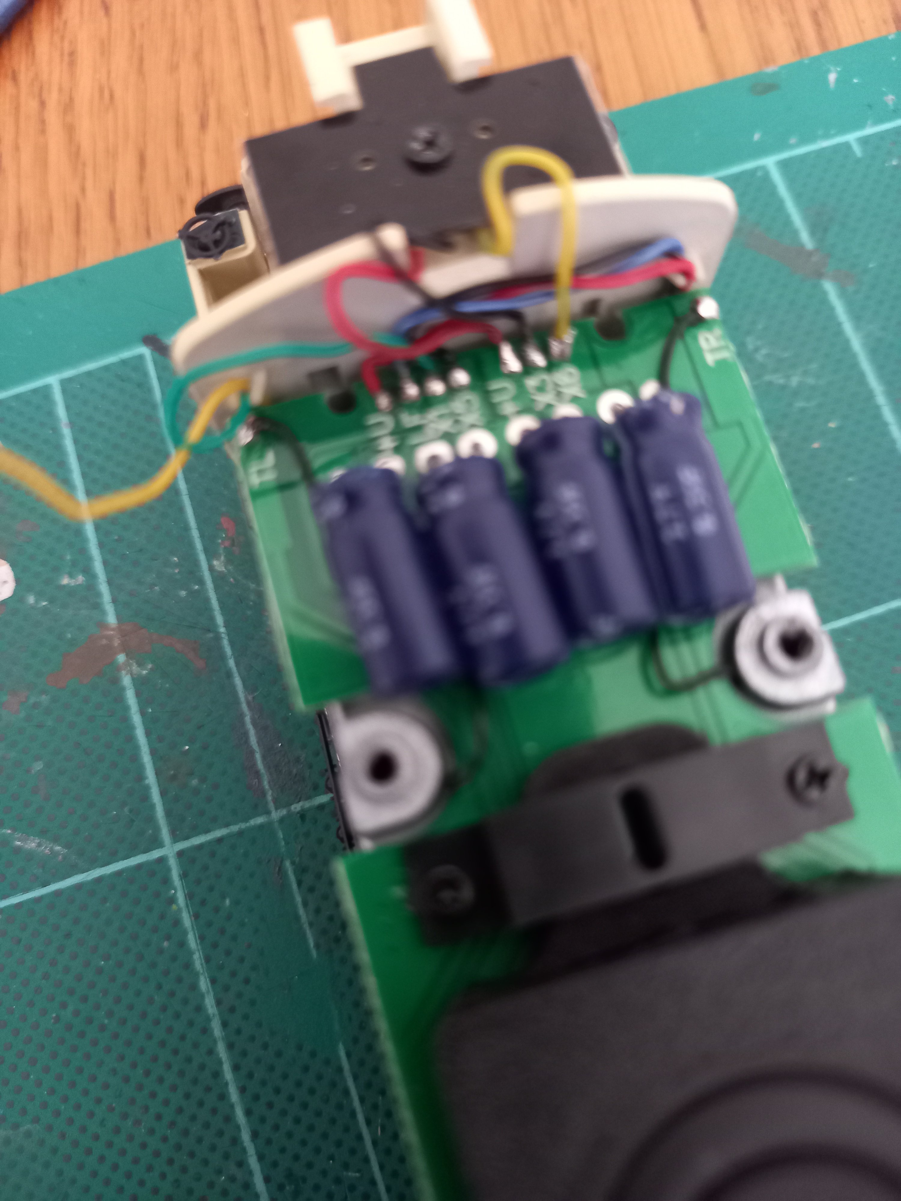
The Capacitor End : Not a lot of space to work in, same procedure as above, except start with releasing X6 first and then X5. The cab light wire is X5, again there is a black wire soldered underneath to X5 tab. If you are unlucky enough to release black wire resolder it back before doing anything else and give it time to cool, hence only tiny dab of solder to iron. The other wire is X6. Same procedure as before. X5 wire then goes to X6 solder tab & X6 wire goes to X5 solder tab. Using metal tweezers dissipates the heat from the iron through the wire as the wires are very thin. Try to hold the tweezers as far away from iron/solder tab as possible. Don't forget to clean iron after each step. You will see from photos other pcb wires moved out of way, you do not want to touch any wire cover with iron as the cover will melt instantly.
Apologies, the first photo is a little blurry, it shows the wires ex factory.
The last 2 photos show the iron, flux & solder I use.
Good luck & feel free to ask any question.
-
1
-
3
-
-
12 minutes ago, Noel said:14 minutes ago, Noel said:
Is there a published fix for the cab lighting, or how to do this on the IRM support site?
There is a video on YouTube, but I can’t remember where, it was mentioned on here but again I can’t remember where.
I have some photos on my phone that I will post with an explanation of what to do. I’m on IPad just now.
-
A46 sorted at last. Rewired for directional cab lighting, Crossley Sound, drivers and Kadees fitted.
Video is a bit stop n start, be patient.
-
2
-
-
Picked up a Heljan TT for £250 from Rails Sheffield. Looking forward to turning 121 loco’s on it.
-
1
-
-
Noel, did you manage to remove the bogies and what make did you replace them with ?
-
1 hour ago, Jonathan_RK said:
I have just noted a Digitrains video on Youtube.
https://www.youtube.com/watch?v=TJHAZB-pft0
This looks like a demo of an IRM A Class loco with Crossley sound, sound decoder produced by Digitrains.
Presume this is a Digitrains project using their decoder complete with Crossley sound.
Has anyone posted a video of an IRM A Class loco running with Crossley sound, using the IRM ESU sound decoder ?
Tara Junction from Noel of this Parish. As Boskonay said, you can reset decoder as many times as you need.
-
 1
1
-
-
58 minutes ago, Jonathan_RK said:
Quick update - have succeeded in getting A55 to move in each direction, with LokSound decoder, CV29 set to 34, and long address set to 1055. Also works with CV29 set to 32. However, no lights or sound. Haven't changed anything else to impact sound or lights. So at least the LokSound decoder is viable for traction purposes !
I have Larry Pucketts book DCC Projects and Applications Vol 4.
Hi J, have you done a decoder reset as previously suggested by Noel, CV8 to value 8 just in case you mistakenly altered 1 or more CV’s easily done ! We have all been there.
Then set CV 29 to value 34 and set address as well.
-
1
-
-
21 hours ago, Jonathan_RK said:
In response to SP:
I've read the value of CV2 from the LOKSOUND decoder, which was 0003, so I set it to 0001. Alas, this didn't solve the problem. I'll check the value of CV2 on the LOKPILOT decoder, just for comparison.
In response to Noel: If I do a decoder reset on the LOKSOUND, will the reset have any effect on the Crossley sound file ?
In response to F4F: Thanks for your advice. I'll check CV29 and set it to 34 and see what happens.
I have three A Class, one MM B181, and one MM B121, so my address list will be a bit shorter.
Model Railroading No. 47/48 videos.
-
44 minutes ago, fishplate7 said:
Hi James R.
Try Neil Smith at Wheeltappers in the UK.
His website is http://www.wheeltappersdccsounds.co.uk/
His Irish decoder sounds are excellent. But beware, you'll be paying importation duty etc., on them as they come from the UK!
Hope this helps!
Eamonn
I have all my MM locos, 33 in all fitted with Neil’s sound decoders, but I’m UK based.
-
1
-
 1
1
-
-
28 minutes ago, Jonathan_RK said:
In response to SP:
I've read the value of CV2 from the LOKSOUND decoder, which was 0003, so I set it to 0001. Alas, this didn't solve the problem. I'll check the value of CV2 on the LOKPILOT decoder, just for comparison.
In response to Noel: If I do a decoder reset on the LOKSOUND, will the reset have any effect on the Crossley sound file ?
In response to F4F: Thanks for your advice. I'll check CV29 and set it to 34 and see what happens.
I have three A Class, one MM B181, and one MM B121, so my address list will be a bit shorter.
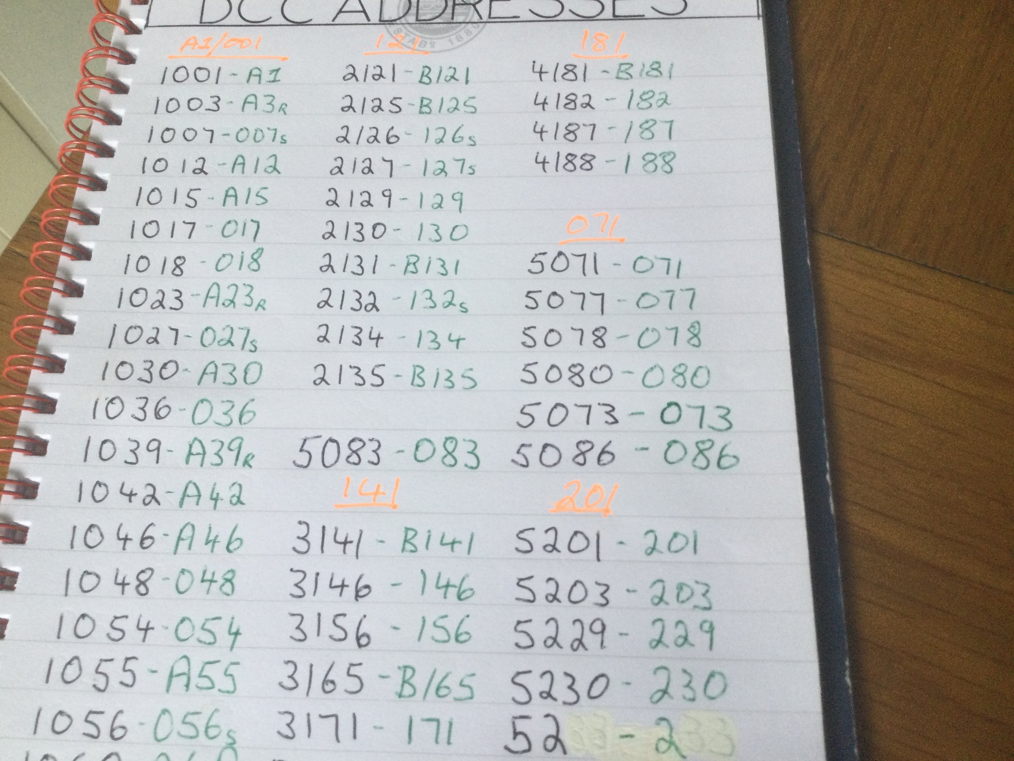
Using 4 digit addresses avoids the problem with any new locos factory set addresses to 3.
-
7 minutes ago, Gabhal Luimnigh said:
Is that how many locos you have?

Yes, 52 locos & four 22000 sets on order, and no I’m not a millionaire, just a retired UK based train driver with a pension and no mortgage.
-
1
-
2
-
2
-
-
Hi J_RK, Good advice from SP & Noel, when you read the sound decoder did you switch off Analogue Control ? If not I believe that could be the cause of your problem. If you are using a 4 digit address, Set CV 29 to value 34, that gives you 4 digit address, 128 speed steps, analogue off, & forward direction of travel. You must use programming mode and on rolling road or circle as previously advised. Look up Model Railroading on YouTube, Larry Puckett has 329 videos one or more that deal with programming decoders using Digitrax. Attached a photo why I use 4 digit addresses.
Let us all know how you get on.
-
2
-
4
-
-
Hi J-RK, I only use ESU Sound decoders, it works fine, moves in both directions with all functions working. Same for A12 & A30 all 3 with the Crossley decoders. A15, A42 & A55 are fitted with EMD decoders.
I should also mention that all 19 of my IRM A/001 class locos have been rewired to enable F11/F23 to work as per the instruction sheet. -
Hi, I use ECoS 52100 Controller. I have had a problem with A46, eventually the problem was sorted with the screws holding the body to the loco. I resolved it by not replacing the 2 screws at the capacitor end. There are 2 black wires that go down by the screw fixings seemed to make the problem. Just be careful how you lift the loco. Feel free to clarify any issues.
Regards
F4f.
-
1
-


Past-Avenue 3D prints
in Workbench
Posted · Edited by Fowler4f
Edit
*