RichL
-
Posts
164 -
Joined
-
Days Won
4
Content Type
Profiles
Forums
Events
Gallery
Blogs
Everything posted by RichL
-
D&B/County Donegal Drewry Railcar Interior Query
RichL replied to RichL's question in Questions & Answers
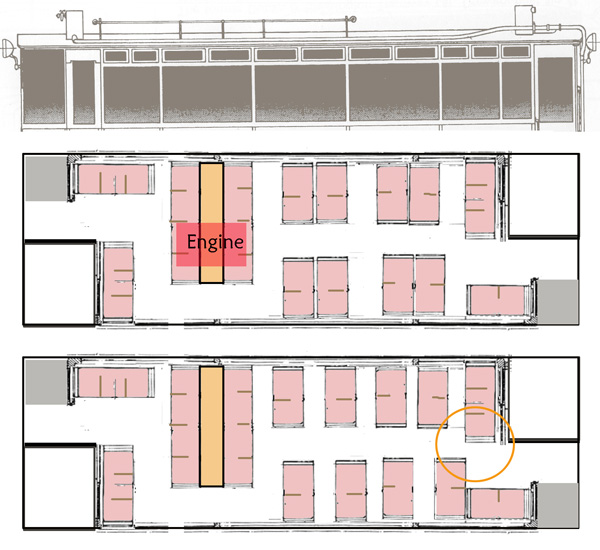
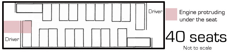
Last stab at ideas, then I really will have to put this aside for a while and catch up with everything else. I decided to try doing a proper scale plan of what the original interior might have looked like with the engine stuck in the middle of the passenger saloon. I found a scale drawing of a contemporary (1920s) tram interior and scaled seats and seat spacings from that. What quickly became evident is that there isn't a lot of space inside the saloon! I don't see how room could be made for all the passengers unless some sat over the engine. The best I could manage was a 35 seater. That was the original specification, but not what people generally assume. Apart from the IRS Drewry book, everyone states 40 seats - but I wonder if that was based on observation after the vehicle was converted to a trailer? It would be interesting to find out when the 40-seat capacity idea first appeared. I think we can reasonably assume that the seating was rearranged once the engine was gone. After all, having all the seating facing in one direction appears to have been a common characteristic of Donegal trailers. This seems a bit unlikely to me whilst the vehicle was a bi-directional railcar. Surely, there would have been seats facing in either direction, or possibly tramcar-style reversible seats? Removing part of the cab partitions increased the space available for seating too. Firstly, I tried the engine in dead centre, but that doesn't work very well. It wastes seating space. Also, it looks messy from a mechanical point of view. When I looked at the Kalka Simla drawing and a similar drawing of the Drewry Barbados bogie railcars, it is evident that engine, clutch, gearbox and chain drive were all arranged in a line. Getting some of it to double back to the centre of the vehicle would be a bit awkward. Maybe the comment about the engine being placed centrally is being taken too literally? Eventually, I placed the engine more or less where it would have been located on the West Clare railcars, for which we have some positive information. Here, the engine seems to have been placed more or less over one of the axles. There were back to back seats over the top of it, placed widely apart, with some sort of cover in-between the backs. This gave a much better use of the space. Even so, I could only reasonably come up with 35 seats. Other assumptions were that the driving cab filled half the width of the vehicle, which I raised a few posts ago - and that the aisle went one side of the engine, not both. The best I came up with was this - but with only 35 seats, as I said earlier. With the driver's cab filling half the width, there was not enough room for 2-aside lateral seating at the ends. The second plan shows an alternative with as few back-to-back seats as possible, but the orange circle highlights why it wouldn't have worked very well. This is an attempt at a scale layout, whereas my previous sketch a few posts ago was just a sketch. It could also be completely wrong!
-
D&B/County Donegal Drewry Railcar Interior Query
RichL replied to RichL's question in Questions & Answers
I've had a look through my copy of 'Classic Tramcars' by Wiseman. Tram manufacturers had distinctive house styles. Both Brush and Preston (Dick Kerr/English Electric) both used wide side windows with two half-length toplights like the D&B car. Brush built batched of the distinctive Sheffield 'Rocker Panel' cars with very curved windows at the front corners up to 1925 - only a year before the D&B car was built. I know I am making 2 + 2 equal 100, but Brush might be a good place to start looking for the body manufacturer for the Blessington railcar. I had a look online at the Crich Tramway Museum collection. Nothing useful that I can find. They do have a good collection of Dublin Tramways images online though. Also, I notice from the book that upholstered, reversible seating was pretty standard on new trams by the 1920s. It might well make sense for whoever built the body to use what was available rather than make custom seats specifically for one railcar. -
D&B/County Donegal Drewry Railcar Interior Query
RichL replied to RichL's question in Questions & Answers
I've had a thorough look through the IRS Drewry book, which draws from original records. This specifically mentions the D&B railcar as a chassis, rather than a complete railcar. This is mentioned in a summary of Board minutes, where the Baronial Guarantee system is explained in relation to whether the D&B could pay for the machine. It is also mentioned elsewhere in the text and in the Builder's List. The latter is very comprehensive - even listing the ship and destination port for most overseas orders. It is silent on how the D&B chassis was despatched, though the West Clare railcars were despatched by the LMS. I wonder if Drewry supplied the chassis and maybe the body was added by another English contractor before it went to Ireland. That might give most observers the impression that Drewry supplied the lot. Brush/Falcon was only just up the road from Baguley's Stafford works, in Loughborough, for example. I suspect they had supplied at least some stock to the D&B in the past. One of the double-deck tram trailers (at least) looks pure Falcon. They certainly built tram and bus bodies. Dick Kerr in Preston was another contractor building tram bodies. They did other work for Drewry, I believe. -
D&B/County Donegal Drewry Railcar Interior Query
RichL replied to RichL's question in Questions & Answers
The Kalka Simla car was designed to provide an express service for first class passengers, so probably a bit upmarket for Blessington requirements -
D&B/County Donegal Drewry Railcar Interior Query
RichL replied to RichL's question in Questions & Answers
This page on Drewry gives a rough idea of what the chassis must have looked like - but with the engine somewhere in the middle. It is a slightly smaller car built for the narrow gauge Kalka-Simla railway, but with a slightly larger engine - and a driving position at one end only. See photos and drawings dated July 1921 -
D&B/County Donegal Drewry Railcar Interior Query
RichL replied to RichL's question in Questions & Answers
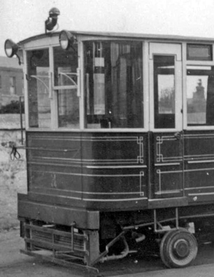
Wow! Parts of that are very different to what is told elsewhere! There would only have been one motor, at least according to Baguley/Drewry records. If Drewry built the whole thing, then the Staffordshire Records Office Baguley records looks like the place to explore without a doubt - they built the railcar. Drewry was just a sales organisation. The problem might be that a lot of drawings and photographs are apparently missing. If you look very carefully at the front of the railcar in the original photo, there is clearly like a handrail with some loops attached, just below the windscreen. This must be part of the bicycle-carrying setup, I guess. What we have found out so far just goes to show you shouldn't take anything for granted. Mind you, if I had not asked a simple question, I could probably have built a railcar by now Still, I do feel we are making progress! Many thanks again for your excellent help. -
D&B/County Donegal Drewry Railcar Interior Query
RichL replied to RichL's question in Questions & Answers
Thanks JHB. Help much appreciated! Just as an addendum to my last post, I got 'The County Donegal Railways Companion' through the post today. This clearly shows the side that definitely had a driver's door - with the door replaced by panelling and windows. It also says there were originally 2 driver's doors. The curved glass panels for the driver's cabs lasted into Donegal days before being replaced by solid panels. Even the starting handle was moved. There is a photo of the interior, looking towards what I have called the A end, but only after final withdrawal. There were 3 or 4 different radiator arrangements too. Despite a reputation for economy, the Donegal seems to have done a fair amount of fiddling around with this railcar. The big problem with research will be that no one seems to know who built the bodywork - and therefore designed the interior. I have a horrible feeling I will end up with a good understanding of the exterior and its history, but very little to do with my original question -
D&B/County Donegal Drewry Railcar Interior Query
RichL replied to RichL's question in Questions & Answers
For anyone modelling this vehicle accurately, even in CDR days, it seems a minefield. Even in the short time it was a powered in CDR days it seems to have undergone several changes. I am going to have to put this on the back foot for a while, so I can catch up on other things but will come back when I have found more photos and possibly have a few more answers. Many thanks everyone for your help. -
D&B/County Donegal Drewry Railcar Interior Query
RichL replied to RichL's question in Questions & Answers
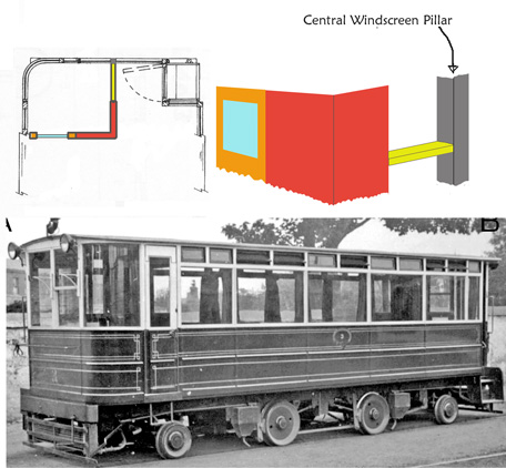
Here's my interpretation of the cab areas, from careful examination of the early photo of the D&B railcar. It is garishly coloured to aid identification. Looking closely at the interior, both ends appear to have an L shaped partition with a small window behind the driver's position. The partition extends to roughly level with the passenger door, from where it is open. There is what appears to be a metal or wooden bar(yellow bit)extending from the end of the partition to the central pillar of the front windscreen (in grey), just above the bottom of the windscreen. Looking at more recent photos, the part of the partition colour coded red was removed at some stage, leaving just the orange coded bit with the window. This part still exists in preservation - at least at one end. Here is the combined version
-
D&B/County Donegal Drewry Railcar Interior Query
RichL replied to RichL's question in Questions & Answers
Many thanks for that link, Garfieldsghost. I had an idea to find out where the Drewry records are kept, but you have saved me the trouble. That is much closer to me and fairly easy to get to. I will make further enquiries. Incidentally, one of my newly-ordered books arrived today - The Light Railcar In Western Europe by WJK Davies. This states that the engine was centrally mounted at and above floor level. Some of his information about other railcars conflicts with other sources (like in the case of the WC&P car, where he states the engine was transversely mounted, whereas the IRS Drewry book shows it was in line). His statement on the D&B car does seem pretty definite though - and feasible. If he is right, then I suggest it is likely to have been mounted centrally on the chassis, supported by the frames. Information on the West Clare cars suggests that their engines were mounted this way too - though towards one end of the body. The West Clare cars had two four-seat bench seats mounted back to back, mounted over the engine, with an aisle at one side. Certainly, a centrally mounted engine on the D&B vehicle would kill the idea of a central aisle all the way along the saloon in its original form. The railcar was converted to a trailer in 1941. The removal of the engine could (I assume) have been a reason to change the seating. The more I find out, the deeper the mystery gets. I thought it was just a quick and easy query when I started the thread! The book also includes a good 3/4 view of the railcar after conversion to a trailer. -
D&B/County Donegal Drewry Railcar Interior Query
RichL replied to RichL's question in Questions & Answers
Just found a spanner in the works regarding my driver's door theory. The photo in the 7mm Narrow Gauge Association's drawings book seems to show the same side as the top photo in my last post, but with what looks like a driver's door. The image is poor quality, but it definitely doesn't have the toplight. That might mean the driver's door/doors were rebuilt - possibly when the vehicle was converted to a trailer? I need to look at more photos, I think! I have also been examining the interior of the car, as shown in the photo in original condition. Hopefully, I can convert what I see into some drawings sometime soon. There appears to be an L shaped partition around the driver's cabs coming across more or less to the centre line of the car. Much of this seems to be missing in CDR days, with just a small windowed partition behind the driver. -
D&B/County Donegal Drewry Railcar Interior Query
RichL replied to RichL's question in Questions & Answers
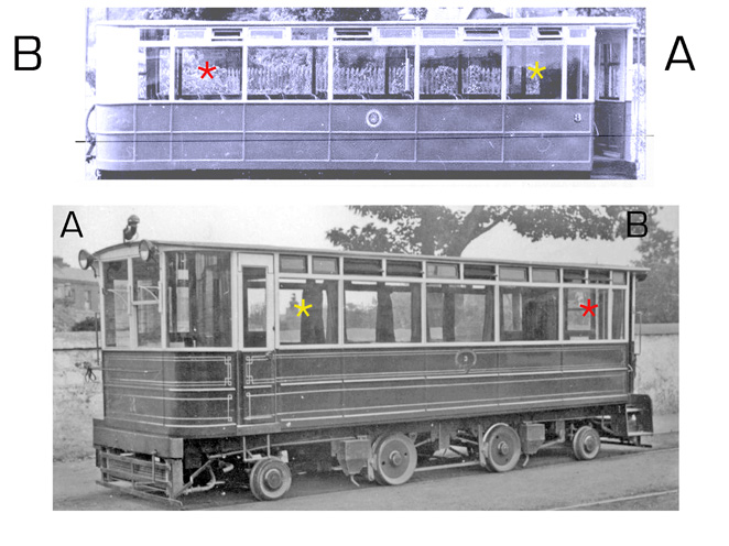
Just to try and make a few things clearer, here's a composite image of the railcar in its original form (lower) and final form (upper) End A is where the engine would be sited - on the lower image you can just see the starting handle and the exhaust pipe. End B would be engineless. End A on the lower image clearly has a driver's door. End B on the upper image doesn't - but it is in its final form so could have been removed. How do I know we are looking at the railcar the other way round? It's easy. The coloured asterisks show the windows that are opposite-handed on different sides of the railcar. The red asterisked windows are wider than the yellow asterisked windows. One other point. You can clearly see the tops of the seat backs in the top picture. No sign of them in the bottom picture. Admittedly the vertical angle the photos are taken is very slightly different, but I would have expected to see at least a hint of the tops of the seat backs on both. Possibly proof that the seating was different in later life, but I'm not going to put any money on it just yet. I really need to find more photos to work from. I have a few County Donegal books on the way. Unfortunately I can only find 2 photos in D&B days, one of which is very poor.
-
D&B/County Donegal Drewry Railcar Interior Query
RichL replied to RichL's question in Questions & Answers
Sorry, there were a few railcars pre-WW2 with underfloor engines, like the Leyland railbuses for the LMS - but thse had a lot more space under the floor. The D&B car had a vertical Baguely engine, as I said earlier. The wheels, pony trucks, springs and transmission would more or less have filled the entire underside of the D&B car. As far as I can tell, all other Baguley-built railcars of this period had the engine above the floor - either in a boxed structure or under seating. -
D&B/County Donegal Drewry Railcar Interior Query
RichL replied to RichL's question in Questions & Answers
Unfortunately there was definitely no room under the floor for the engine. I have looked at the drawings in 'The Engineer' for the very similar Drewry Kalka-Simla railcar. The pony trucks and their springs, the main wheels and the transmission filled the entire area under the floor. It was only once horizontal engines were developed (after WW2?) that underfloor engines became practicable for railcars, I think - and when Drewry designed their first ones (for New Zealand), they had to use engines from FIAT which were then the only ones available. The railcar was definitely fitted with a Baguley engine. This is recorded in Baguley-Drewry records, which still exist. The Baguley engines all had vertical cylinders - though not particularly big. They were low enough to fit seats over (as in the West Clare cars), but not to walk over. The only place for the engine was above the floor. I think it could only have been at the end next to the driver - and sticking slightly into the passenger saloon. Otherwise why have a driver's door at all? If there was no engine in the way, the driver could have easily got in and out using the passenger door. Regarding the driver's door, I think I may have confused everyone. It was at one end only - the end where the engine was sited. As far as I can tell, it lasted into the CDR period. The end where it looks like the driver's door was filled in maybe never had a door at all - there would have been no need for one, as the engine was at the other end of the vehicle. Similar railcars were also built for Tasmania. These too had the engine in the same place - though more powerful. The bodies were built locally though, so otherwise there is little to learn from them. -
D&B/County Donegal Drewry Railcar Interior Query
RichL replied to RichL's question in Questions & Answers
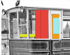
Here is said door, from the photo we think is of the railcar when brand new. This is definitely the opposite side to the one shown above (comparing a photo with the drawing)
-
D&B/County Donegal Drewry Railcar Interior Query
RichL replied to RichL's question in Questions & Answers
Agreed the corner is different - but looking at photos, the panel was a direct replacement for a curved window. There definitely was a door for the driver at one end, so that's 3 doors altogether. See my original photo, left hand side which clearly shows a door handle, door edges and a step below.... ...whereas the latest photo shows just a plain, narrow window (wider than the one in the door) with panelling below. This is definitely the diametrically opposite corner to the one with the driver's door. I have worked out that the saloon windows were arranged in a different order, so I can now tell which side is which. Assuming the engine was at the front, the driver would need a door to get into the cab. Otherwise he would have to climb over the engine. At the other end of the railcar there would be no such obstruction, so he could use the passenger door. -
D&B/County Donegal Drewry Railcar Interior Query
RichL replied to RichL's question in Questions & Answers
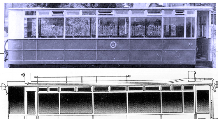
To be honest, my sketch of a possible interior was never drawn to scale. I really ought to do that to get a better idea of what would have been possible. I still feel strongly that 2 + 2 seating with a central aisle at the engine end would have been impossible, because I feel the engine would obstruct access to the passenger door. Here is my best proof that the well known drawing of the railcar is slightly wrong about the side windows The two windows either side of the central group of three are definitely noticeably different widths in the photo, but not in the drawing. On the other side of the body, these windows are swapped over so that the wider window is to the right. The photo strongly suggests no driver's door at one end too.
-
D&B/County Donegal Drewry Railcar Interior Query
RichL replied to RichL's question in Questions & Answers
Many thanks JHB - I will definitely bear that in mind. Very kind of you -
D&B/County Donegal Drewry Railcar Interior Query
RichL replied to RichL's question in Questions & Answers
Those photos do sound rather interesting...... -
D&B/County Donegal Drewry Railcar Interior Query
RichL replied to RichL's question in Questions & Answers
Thanks again for all the help and advice - and confirmation of the engine position. I have good drawings for the Kalka-Simla 2-4-2 railcar which must have had a lot in common, including a wealth of detail of the underframe and controls. They might help me build up an good picture of the details - thoughthis car was slightly smaller and had a slightly larger engine. The difficulty is that Drewry only supplied the chassis, so the internal layout of the body could have been a one-off, with no resemblance to anything else. The body looks very tram-like. Not sure if the bodybuilder was copying a tram style, or actually was a tram body builder using standard parts. It seems to be unknown who built it. The windows do bear a close resemblance to the parts in a Kiel Kraft Birmingham tram kit in 4mm scale, so I may cannibalise one of those for my model. The body is peculiar with the narrow entrances and the deeper cabs - and the engine would have to protrude into the passenger compartment to some extent, but would comfortably fit under seating. If I were designing a railcar body for 2 + 2 seating all along, I wouldn't lay the body out quite that way. But then, who knows what constraints and opinions gave us that design anyway I am in no rush to start work on the model as I have lots of other things on my plate at the moment, including organising my mother's 90th birthday. Plenty of time to think and possibly unearth other information. A visit to Cultra would be very expensive - I would probably have to try and make the flight worthwhile by staying in Ireland for a holiday or something. Maybe next year, as there look to be lots of interesting things to see there. My worry would be that, short of dismantling some of the interior, much of what I would be interested in would be invisible under the flooring. -
D&B/County Donegal Drewry Railcar Interior Query
RichL replied to RichL's question in Questions & Answers
I have thought a lot about the D&B Drewry railcar over the last few days (as well as steep inclines). My gut feeling, based on the layout of the other 2-4-2 Drewrys is that the engine on the D&B version was probably at one end, above floor level and more or less on the centre line of the chassis. There wasn't room under the chassis. The only other place it might have been is under seats in the passenger saloon, like the West Clare railcars. Either way, a central aisle all the way along the passenger saloon would not be practicable with the engine in place. The aisle would somehow have to shift sideways to get around it. Here is just one thought on how the interior could have been laid out originally - making sense of my guess on the engine position, the size and position of the doors and the position of the partitions behind the driving 'cabs'. Of course, once the engine was removed there would no longer be an obstruction, so full 2 + 2 seating with a continuous central aisle would be more practicable. My theory would only work if the current interior is not quite original. It has already been pointed out to me that it is unlikely the County Donegal would spend money on refurbishing the railcar, so I could well be completely wrong.
-
D&B/County Donegal Drewry Railcar Interior Query
RichL replied to RichL's question in Questions & Answers
Hopton Incline 457 yards (418 m) 1 in 14 gradient Taken from Wikipedia, but confirmed elsewhere -
D&B/County Donegal Drewry Railcar Interior Query
RichL replied to RichL's question in Questions & Answers
The D&B wrote to Drewry specifically mentioning the requirement for a railcar to get up their steepest gradient which was 1:17 for a distance of 50 yards. They sent a full gradient profile with the letter. The 1:14 gradient is on the line in Derbyshire - nothing to do with the D&B -
D&B/County Donegal Drewry Railcar Interior Query
RichL replied to RichL's question in Questions & Answers
There was a 1:14 gradient on the Cromford & High Peak Railway in Derbyshire, England but it was only approached at a rush and with just a couple of wagons. This was originally a rope worked incline. I finally found a side elevation photo of the Drewry, though in unpowered trailer condition. It confirms my suspicions that the Beattie drawing is wrong about the width of the different saloon windows. It also suggests there may only have been a driver's door at one end. That implies to me that the engine was situated next to the driver at one end of the vehicle, unlike the West Clare 4-wheel railcars where the engine was underneath seats in the passenger saloon. Only a guess, but it is looking more likely than before. -
D&B/County Donegal Drewry Railcar Interior Query
RichL replied to RichL's question in Questions & Answers
The specification for the Drewry ralcar apparently required the design to achieve 6mph over the max. gradient of 1 in 17 and a max. speed of 16mph on the level. Not very ambitious, but I assume the line must have been subject to severe speed restrictions with it running next to a road nearly all the way (officially, anyway!)