
RichL
-
Posts
164 -
Joined
-
Days Won
4
Content Type
Profiles
Forums
Events
Gallery
Blogs
Everything posted by RichL
-
Many thanks everyone for your help and enthusiasm! Fairbairns are great if you are modelling the Waterford & Tramore, but 'Victoria' has all the hallmarks of being designed by someone who didn't really know what steam locos were supposed to look like It is very unusual in a number of ways. Of course, some of the oddities might date from when she was running on the NW&R, but we shall probably never know. The GNRI book suggests she was originally built for an exhibition in Dublin in 1850 and later bought by Dargan to run on the NW&R, which he operated under contract for a while. The spacing of the wheels, with the front axle so far forward almost suggests that it was originally planned as a 2-2-0T I think there was an article on Grendon locomotives some time in the 1970s or 1980s in the IRRS Journal which might give a few more details. Otherwise, I suspect the photo is all I really will ever have to work from. The only other actual Grendon loco I have seen a drawing of is on p29 of the same GNRI loco book. This is an 0-4-2 tender loco of 1849. The book suggests it is a conjectural drawing and it shows little detail. Incidentally, there are some other really tasty locos in that book, including a couple of 2-2-0 tanks - maybe for another time! No point in getting too obsessed though - if the consensus is that you all want me to have a go, then I shall have to go with what we have. I do have quite a few drawings of other locos of the period, so feel sure I can cobble something convincing together in due course
-
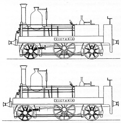
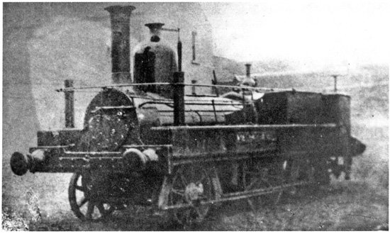
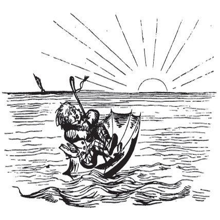
Now that my 21mm/12mm gauge test track is finished I really need to get some stock built. It is a kind of catch 22 situation though. Whilst I pore over countless books getting a hold on the exact nature of my new layout, I have no precise idea of what stock I shall need. Some stock needs building though, if only to build up experience and fill in time before the layout is ready to be built. Firstly, there are a few Dundas Models Irish NG wagons on the go. I needed to get these running to test the test track. I hit a problem with excessive side play on the wheelsets though. Either the axles are shorter, or the bearings are different to those that the chassis were designed for. I have paused on these whilst I work on a solution. I guess that squeezing the bearings in a little should work. I also have a couple of ideas for quick and easy motive power. More about this another time. For 21mm gauge, I have a few wagon kits to put together and an out-of-period diesel to convert to the correct gauge. I am really itching to do a steam loco though. Whilst browsing through my ever growing collection of books, I came across a drawing and photo of a tiny loco for the Newry, Warrenpoint and Rostrevor Railway on page 67 of Locomotives of the GNRI. At around 3" long, it is really tiny in 4mm scale. It is so weird that I really fancy a model. Crazy, but true. So, I have decided to evaluate it to see if I really can model her. It was too hot to do anything energetic this afternoon so I decided to take a deep look at the design. The photograph in the book is very poor ( it was taken in 1885 or thereabouts, so fair enough). The drawing was probably made from the photo. Comparing the two, it seems to me that the drawing is not quite right. Perspective problems on steam locos make accurate scaling from a photo a real challenge, even when you know key dimensions. I scanned the images and started playing around in Photoshop. Firstly, here is the image in the book enhanced a bit to bring out more detail. This shows a few details not in the drawing, like the name of the loco seems to be on a small rectangular projection from the side of the loco, for example. The brakes appear to be only on one side of the loco. The rear bunker appears to be very rounded with pointy ends on the rear buffer beam. Using perspective and scale corrections I then stretched the photo to get a reasonably accurate idea of the proportions of the loco Because the loco photo is taken at around 45 degrees and from near ground level it is impossible to get a true side and end elevation from the photo directly. You can work out the relative proportions though by doing several different perspective corrections independently. The main conclusion so far is that the front end has been drawn too short. Here is the original with a very rough correction below just to give you the idea. . Whether I pluck up the courage to build it or not is a matter for another day, but I am finding the loco thoroughly addictive to study. My next step is to work out more of the relative dimensions more accurately and then maybe build a mock up in card to compare with the photo. The only useful dimension quoted in the book is the driving wheel diameter at 4ft. It was built by Grendon in 1850. Not likely to be any more information to go on. Even the frame details in the drawing are probably conjectural, I guess, as you can't make much out in the photo. Looking at contemporary designs may give me a few pointers to fill in the gaps. By coincidence I already have wheels suitable for her. I would be happy just to see it move under its own propulsion. Being able to haul something would be a bonus.

-
The SL&NC does extremely well!
-
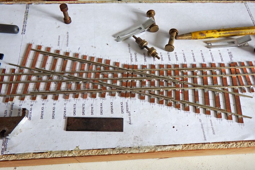
According to this photo it wasn't quite the same as the 3-way drawing - the point blades for the two turnouts look clearly separated to me
-
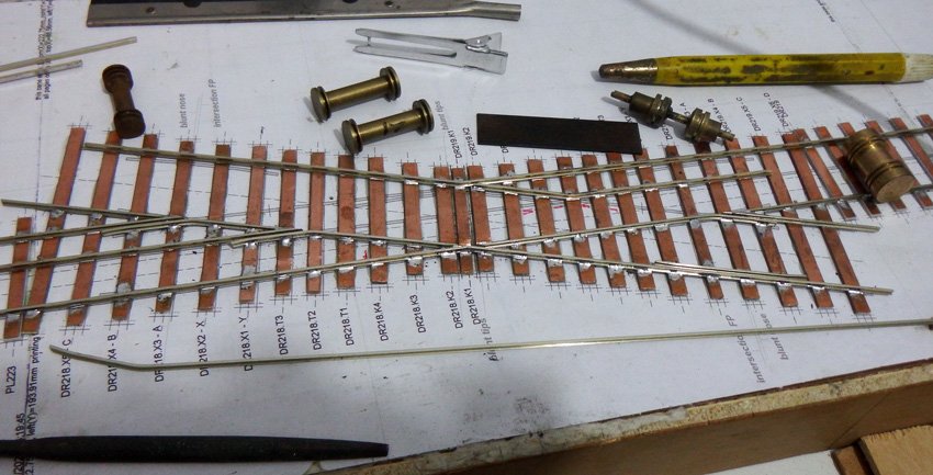
All the check rails are now soldered in place (unless I find I have missed any!) Running with test wagons and wheel sets seems pretty good - both gauges. The Dundas 12mm gauge wheels seem fine too, which gives me a lot of confidence in my choice to go with P4 standards - at least for the time being! I still have the insulation gaps and the wiring to do - maybe this evening, if I get time.
-
Yes, I'm glad I found it too. Lots of interesting detail - especially in the GS&W drawings. I have been looking at lots of photos as well and suspect there is lots of stuff in early track construction, like cast crossing noses for example, that we modellers are not generally aware of.
-
Sticking to Ireland, the impression I get is that many lines were built with absolutely minimal resources - and light F/B rail laid directly on half-round wooden sleepers was just about as cheap as you could get. I think this was very high on maintenance. Baseplates between the rail and the sleepers and better quality sleepers helped a lot. Bullhead made some sense where there is very heavy traffic as it used to be much quicker and easier to replace the rails. There also seems to be imagined prestige attached to being able to show that you could 'afford' bullhead. Looking quickly through a GNRI book I have, there seems to have been little or no bullhead in photos until around 1895 when it was definitely in use on the main line around Belfast, but not in other places. By the 1950s, photos of many if not most GNRI lines show bullhead - at least for the running lines. Another book on the GSR suggests some main running lines had bullhead by the 1920s, but not much else. It was only a quick glance through though. I would have thought that the running lines at Limerick Junction would be a prime candidate for bullhead once it became the standard, if only because it was very busy, so would require fairly frequent rail replacement.
-
Looking at drawings, books and photos, FB was most popular to begin with on most if not all lines in Ireland. The GNR and NCC lines then converted to B/H extensively, with some main lines of other companies gradually being relaid with B/H roughly from the end of the C19. Some lines don't ever seem to have gone B/H. The earlier GS&W drawings in the collection I linked to above were nearly all F/B which I assume was their standard at the time. This is all from casual browsing though - I am not an expert!
-
The drawing is for bullhead, which wasn't so fashionable in Ireland. I think they were only used in sidings even in the UK. Never say never though - someone may quickly prove us wrong! The joggle was necessary to allow room for the second pair of point blades. Joggles in pointwork were otherwise rare, I think, unless you are modelling the GWR (England). I don't want to sound an expert though. Most of what little I know was from a talk I once attended on modelling prototypical track.
-
At risk of getting totally carried away, here's some useful drawings of prototypical Irish track from around the beginning of the C20 https://www.oldpway.info/opw_drawings.html There are some great GS&WR details, amongst others worth studying for anyone interested in old trackwork.
-
...and here is one of my all-time favourite drawings showing just how complex things can get....
-
We could turn the tiebar discussion into a lengthy topic all of its own! Reliability is one issue, along with appearance and operation - and these all conflict with each other to some degree. A prototypical-looking, fully-functional tiebar tends towards being very weak. Then there is the issue of what a prototypical tie bar actually looks like. This varied considerably over time and is a very neglected area amongst modellers. Only to be taken seriously if we really want to, of course - and only a handfull probably do. In 7mm scale realistic and robust enough tiebars are probably possible. In 4mm scale, it is more challenging though one or two modellers have achieved success using novel materials and advanced adhesives. The Ambis tiebar tries to reproduce a relatively modern design. There is a spider-like etch which has to be folded up. One of these is soldered to each point blade with a thin, horisontal, upright aligned piece of PCB joining them together. Masokits do a slightly more robust version with a full-width brass etch which is folded around thin PCB, soldered together and then the insulation gaps are cut. Really old tiebars were made of round rod which passed through the rail and was bolted from the outside. The most outstanding 4mm operating tiebars I have seen are Howard Bolton's on his Minories P4 layout, where everything looks and operates in a prototypical manner, right from the lever frame through operating point rodding to realistic tiebars (or stretcher bars as they are properly called - at least in the UK?) I wouldn't even begin to dream of being able to do things this well.
-
General Motors GM6 six-wheeled locomotive similar to a 121
RichL replied to jhb171achill's topic in General Chat
Looks like a safety feature, a bit like tram locos -
Your track does look very nice! I did think about rivet construction, but almost arbitrarily went for copper clad construction instead - probably in the end because I had only ever tried this method before. Tiebars are a perpetual problem, especially if you want something that looks realistic and is also reliable - almost a contradiction in terms! I have experimented with a few, but never reached a firm conclusion. The more solid and predictable the setup the better though, I think. Worst, for me at least, are the TOUs where wobbly wires extend from an under-baseboard slider to each rail individually. Some people swear by them, but I don't see how they can ever be made to hold the point blades really solidly to the stock rails. I shall be experimenting with mine before I settle on anything.
-
General Motors GM6 six-wheeled locomotive similar to a 121
RichL replied to jhb171achill's topic in General Chat
That's an interesting idea. Probably very heavy though? CIE's solution for the dieselisation of the West Clare seems more likely - assuming Walker were still in business, of course. Heres a couple of other links http://emdexport.railfan.net/demos2.html and a photo.. -
General Motors GM6 six-wheeled locomotive similar to a 121
RichL replied to jhb171achill's topic in General Chat
https://en.wikipedia.org/wiki/EMD_GM6W http://emdexport.railfan.net/demos2.html -
Many thanks for the complement! Handmade track is certainly not cheap any more. The cost of PCB sleepers and timbers has risen dramatically over the years, though quality is a lot higher than the early products. The main benefit for me of using handmade track is to do things that are not possible with RTR track. In combination with Templot, it is possible to design and build complex formations or even just smoother formations that look nicer than the rigid geometry of RTR track allows. Not forgetting the fact that you can build to any gauge/standards you like. There are only 3 more insulation gaps on my diamond than on a simple diamond, as the far 3ft gauge rail merely repeats the far 21mm rail in the above photo, so shares the same polarity changes.
-
The rail order arrived today, so I was able to make a bit more progress on the test track this evening. Hopefully one more session should see all the remaining rails installed
-
Yes, just to point out to everyone that I was referring to your original link https://www.rmweb.co.uk/community/index.php?/topic/122105-what-is-a-cameo-layout/ Your amended link is quite different!
-
I hadn't read that particular topic before, but it quickly degenerates into the usual RMweb flippantry, irrelevance and argument - this one from just the second entry onwards! There are some good points as you progress through - it's just a pain finding them. An obvious candidate for firmer moderation! The emphasis with cameo layouts is on portable layouts and presentation issues are most relevent to exhibition layouts, but much of the advice could equally apply to home layouts.
-
Unfortunately, most published advice on track construction relates to Bullhead - something of an obsession in the UK - to the point that some people happily build or lay bullhead even when F/B is appropriate. In Ireland the balance between bullhead and f/b was far more skewed to f/b, as I understand it. Even then, early and modern f/b are quite a lot different, especially when it comes to pointwork. This affects the way such things are modelled. With my own project, I decided to go for a small test track first mainly because I want to build up an eclectic collection of stock. This will take a long time. I have made the mistake in the past of concentrating too much on the layout and almost forgetting about the stock. With OO and RTR stock, this is not so much of a problem as the chequebook or credit card deals with the latter fairly quickly if you have the funds. With 21mm gauge though, even RTR needs regaugeing, This takes far more time and willpower than might initially be thought. It is easy to grossly underestimate just how much time and effort it takes. I found in the past that I reached a state of mental and willpower exhaustion long before I got to the stock.
-
Stocking your layout will be the real killer, moneywise. You can cut OO track in half and regauge it with a gap in the middle of the sleepers for the fiddle yard.
-
If money were available you could get someone to build the whole layout for you, but where's the fun in that? It is the really long, modern high speed turnouts that are awkward as there is a lot of very careful filing to do. Around a station the turnouts are likely to be a lot shorter with sharper crossing noses, so much easier to file and a greater margin for error in the filing. Working from a really accurate drawing works quite well after a bit of practice. I think most of the pre-made components like those offered by C & L are bullhead, not F/B.
-
Forgot to add that the full details of the solder I am currently using is as follows: Rapid Solder Wire 60/40 22SWG 0.7mm 500g Reel Order Code: 85-0595 It has slightly different characteristics to the last make I used, now unavailable, but now I am getting used to it I find that works very nicely. One reel should last many, many years even if you are building layouts like Limerick Junction For F/B track I tend to tin the bottom of the rail by using flux and applying a very thin coat of solder via the soldering iron tip, using the tip like a brush. Then I solder the rail to the sleepers by applying the soldering iron and the solder wire to the rail/sleeper joint together, no extra flux. Very little solder is required for each joint as this solder flows very nicely.
-
Don't forget the rail and sleepers! Best to try a flat bottomed rail turnout first, as chaired bullhead track has extra complications. C&L are a good source for good quality copper clad sleepers, but idiosyncratic to deal with to deal with, especially you are outside the UK. Whatever the source, they normally are properly used in two widths, 3.3mm for plain track and 4mm for point timbers. For practice purposes it doesn't really matter. There are 2 thicknesses too (depth) - use one or the other of these, not a mixture, either around 1mm or 1.6mm. The diffferent depths allow a match with commercial plain track from different sources. For rail, I guess code 82 flat bottomed rail is best for modern image - same sources as copperclad sleepers. Nickel silver rail is best for beginners as there is no risk of rust encouraged by use of flux. There are other sources, like Marcway in Sheffield and the EMGS. I guess continental Europe has suppliers of similar components too, as there is an HO community building their own track. Using a non-UK source though the rail may not fit the 21mm gauges properly.