gibbo675
-
Posts
205 -
Joined
-
Last visited
-
Days Won
7
Content Type
Profiles
Forums
Events
Gallery
Blogs
Store
Community Map
Everything posted by gibbo675
-
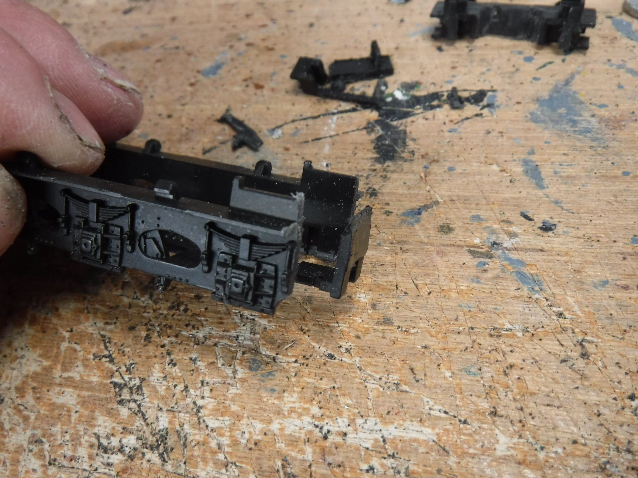
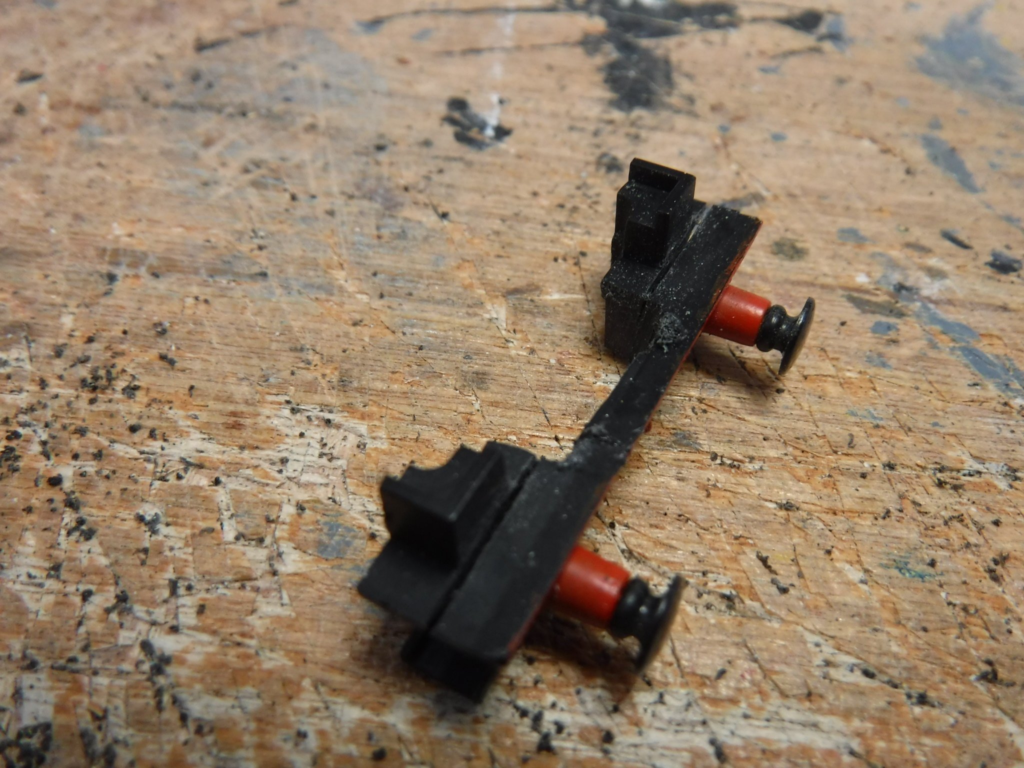
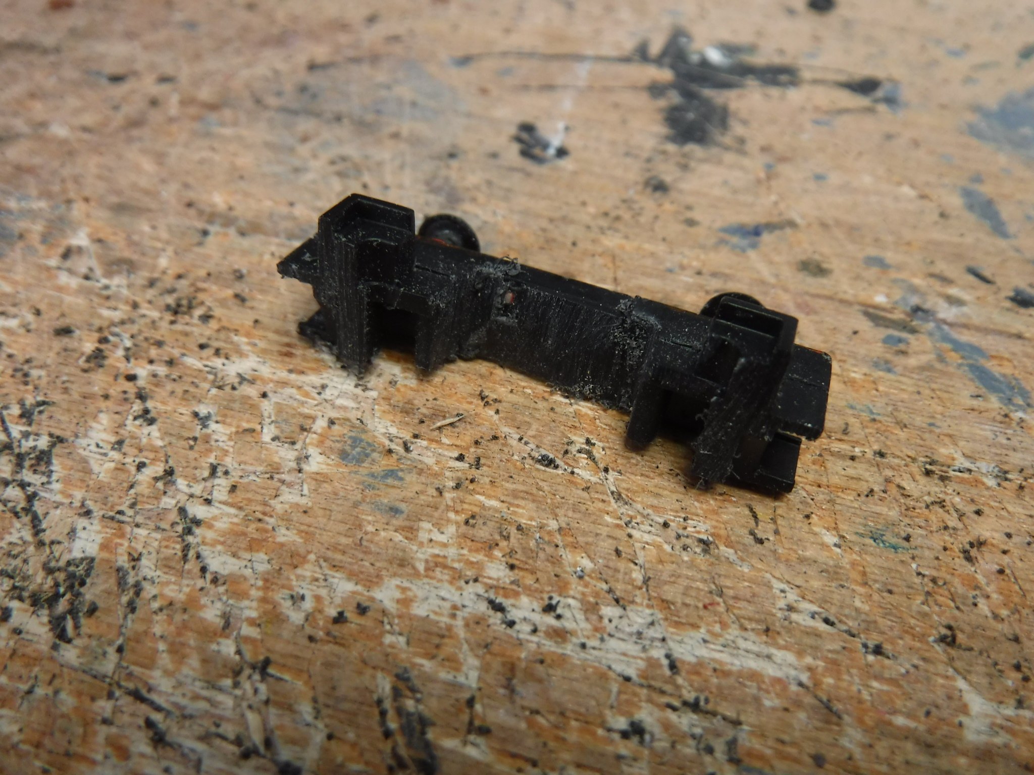
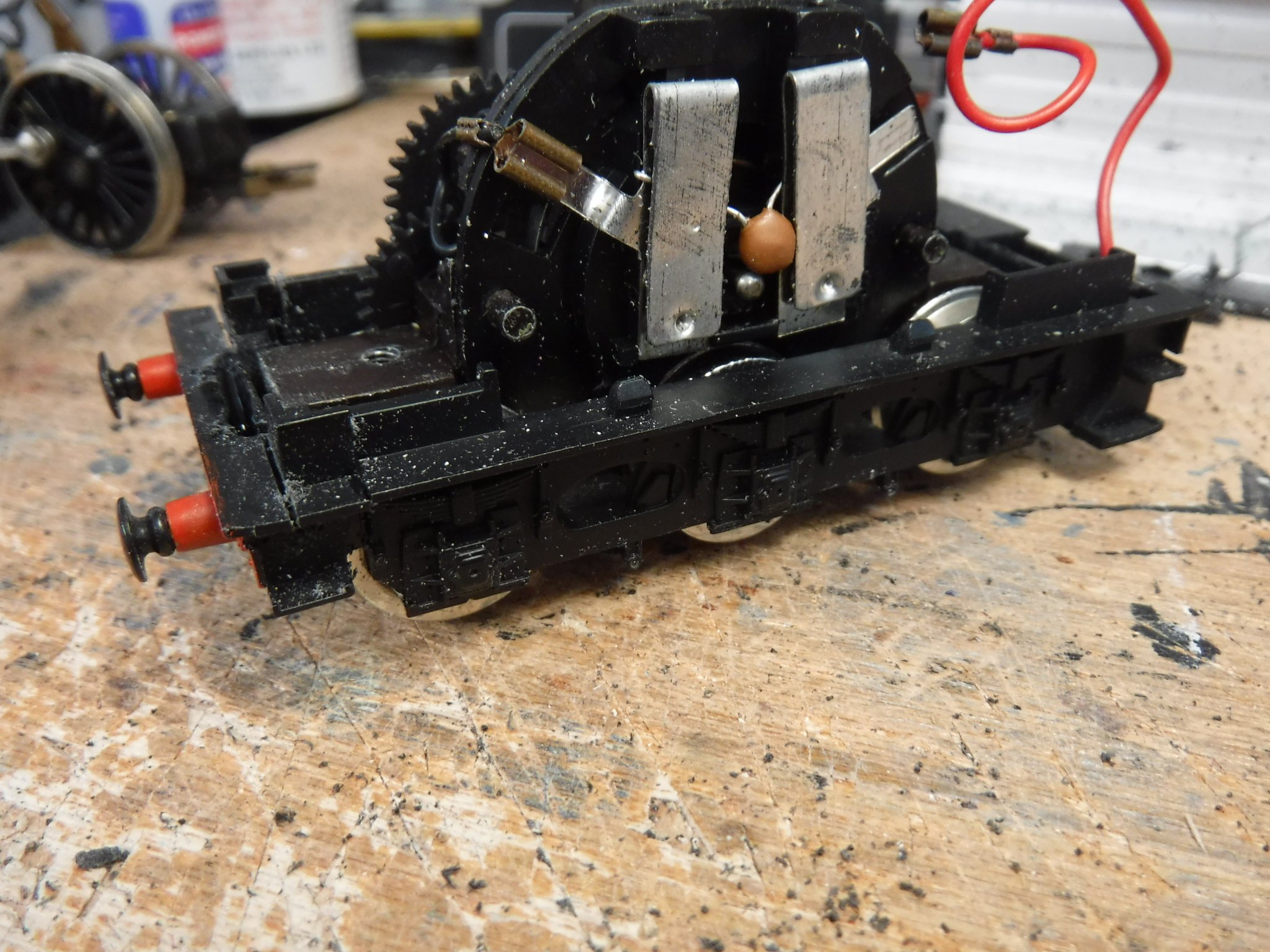
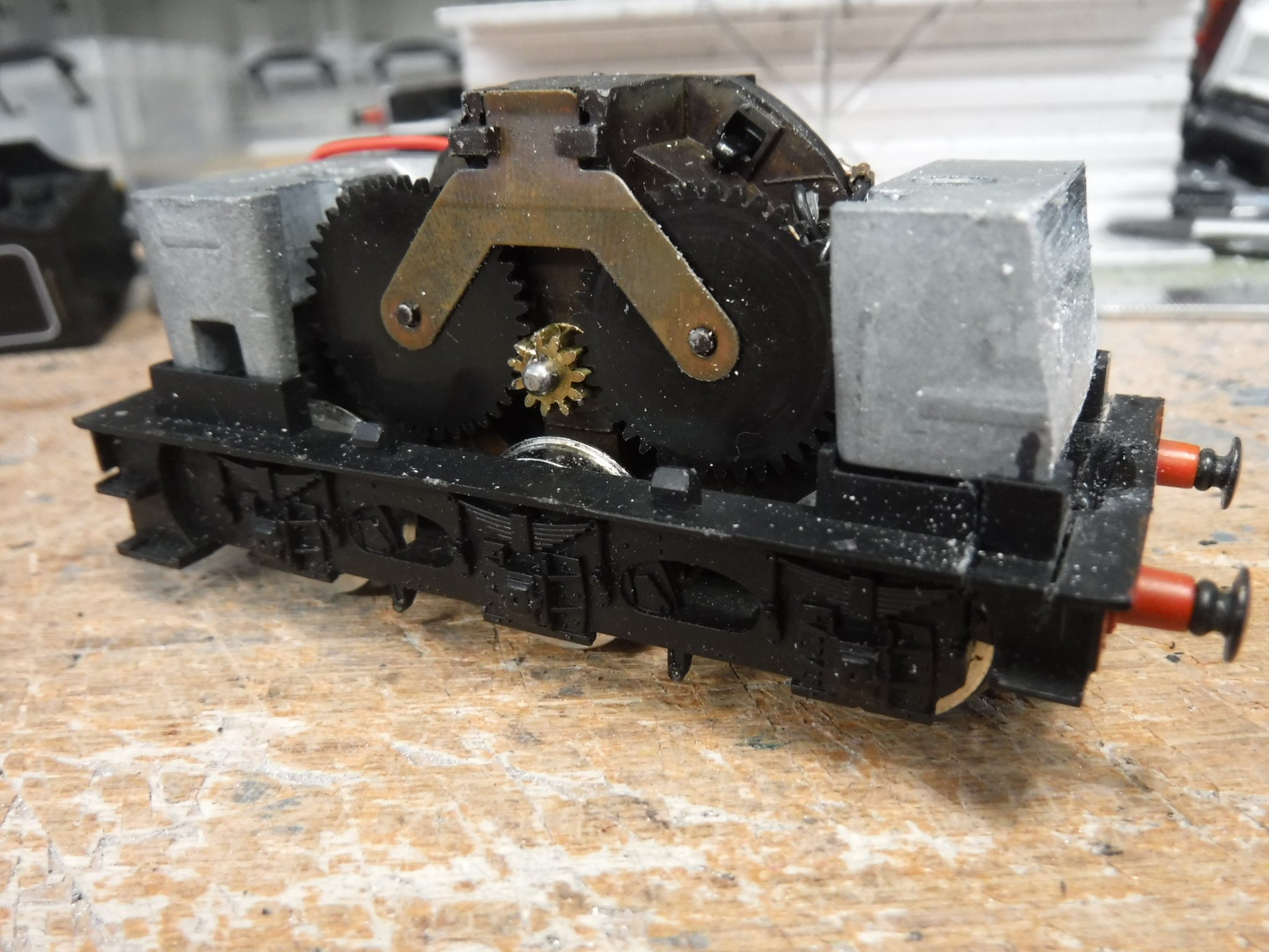
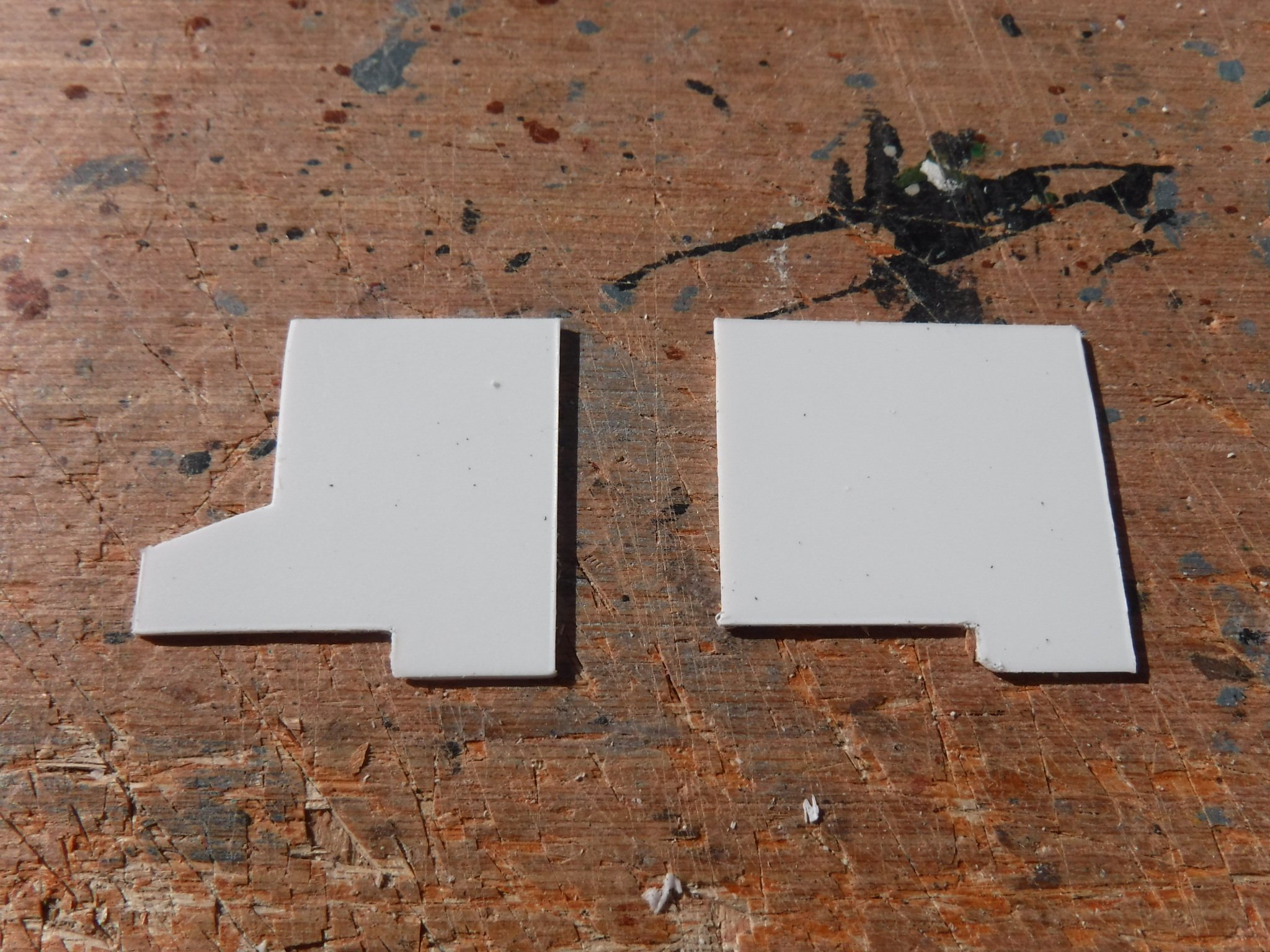
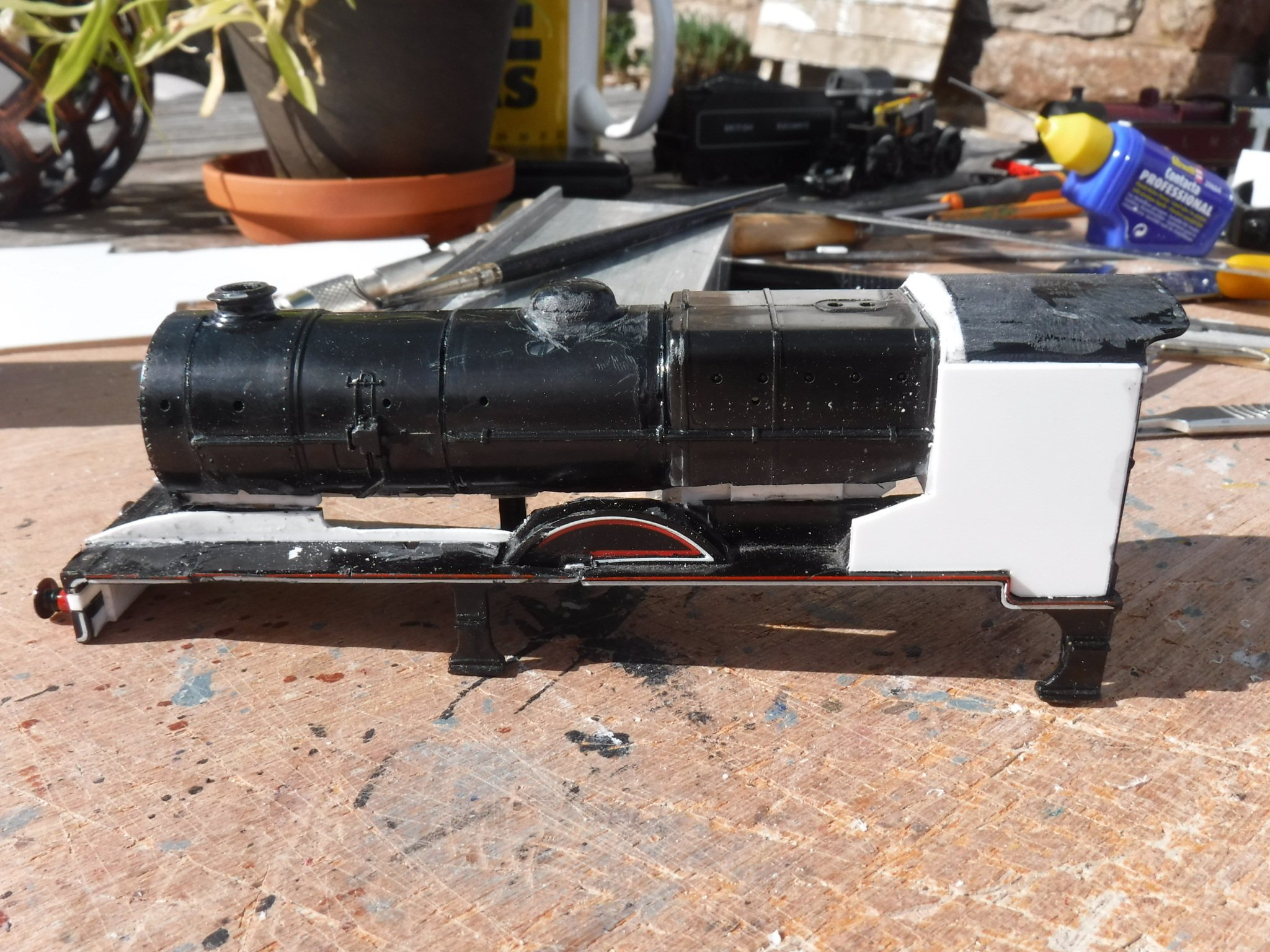
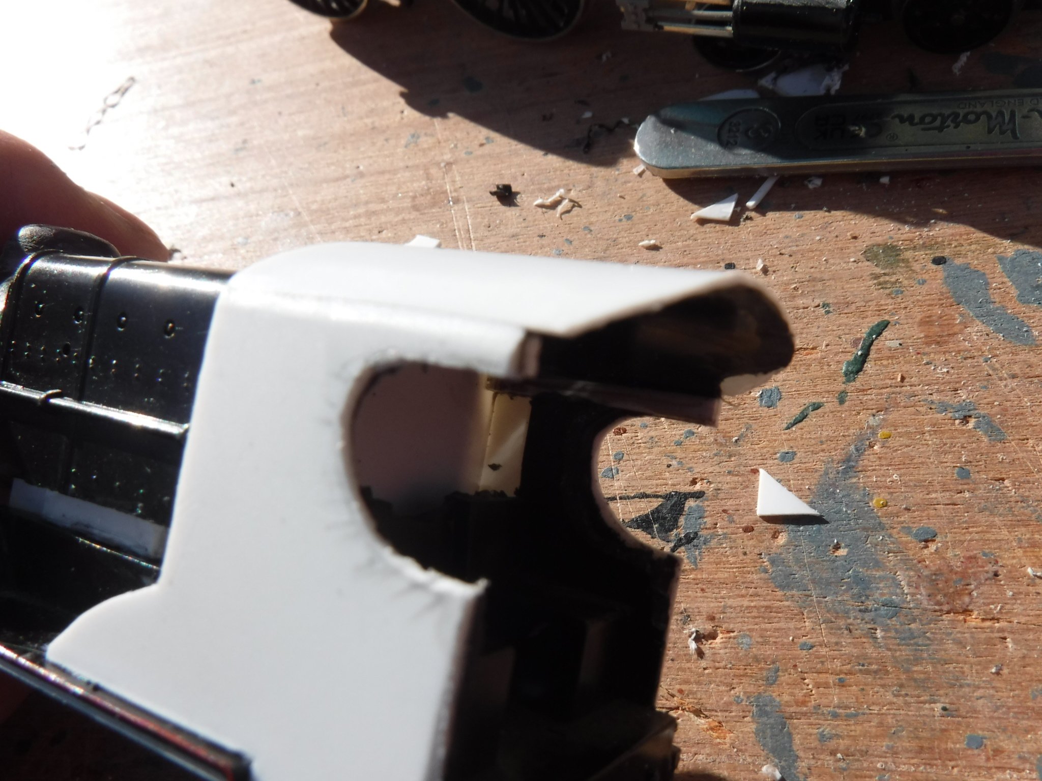
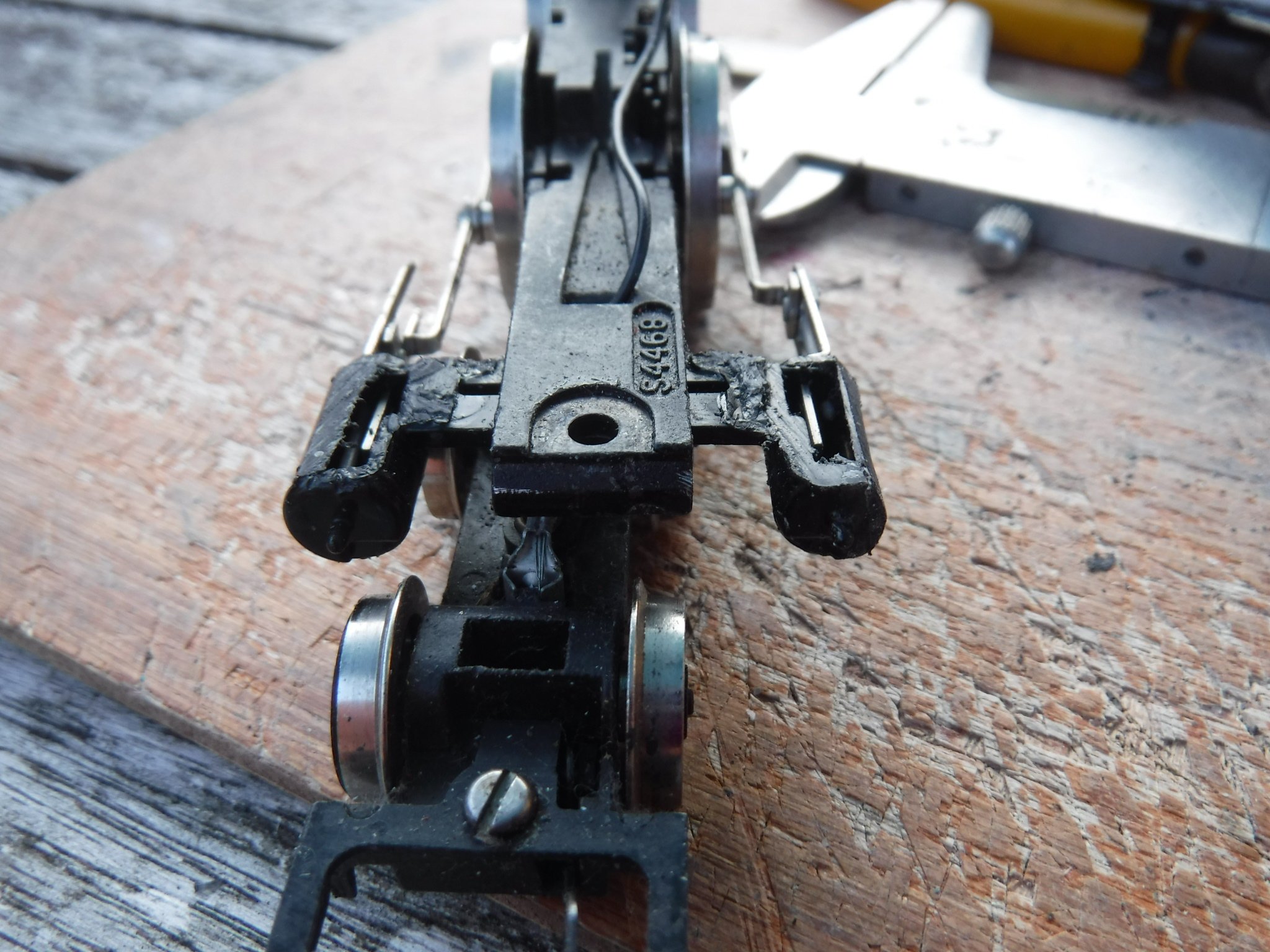
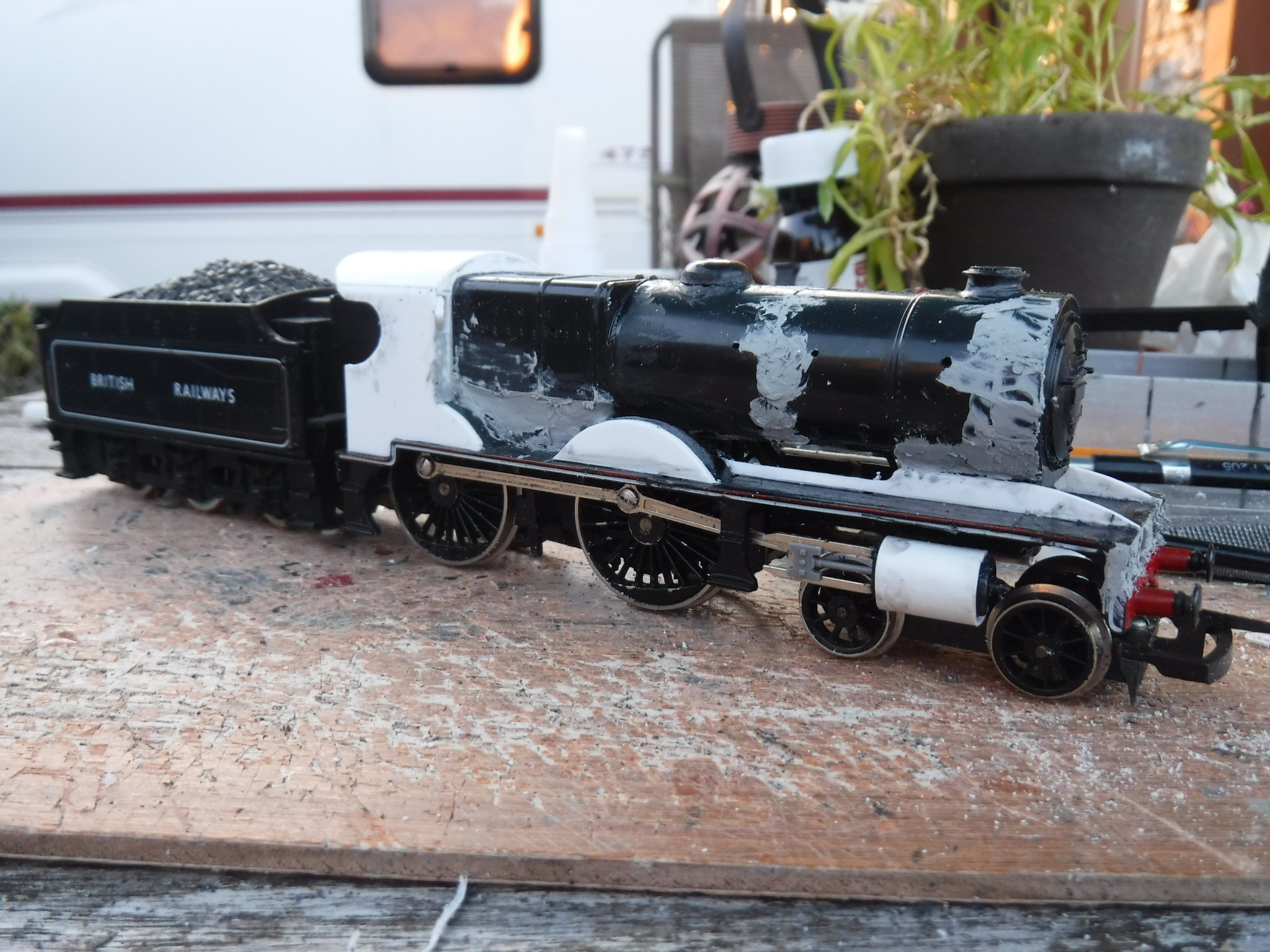
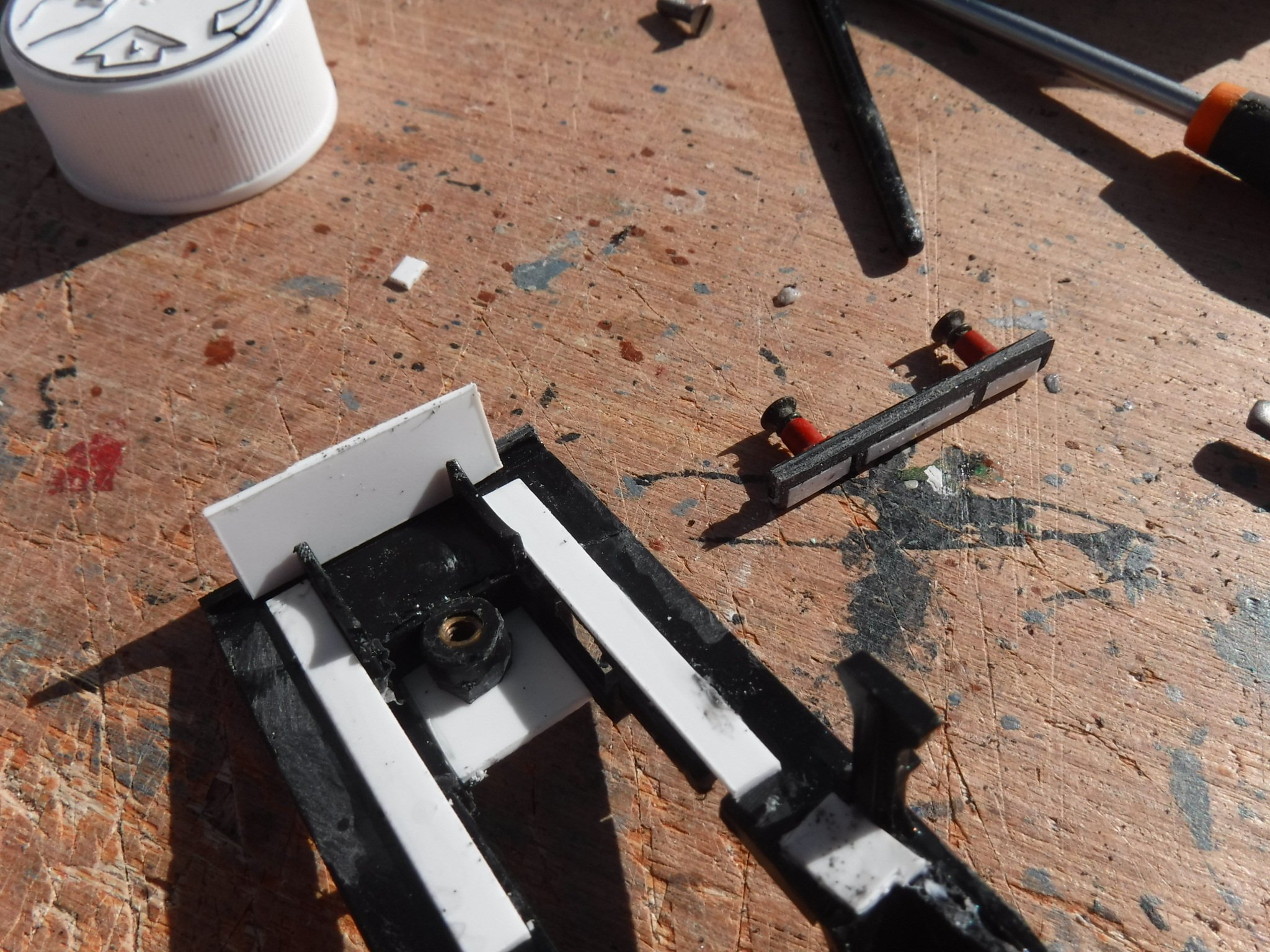
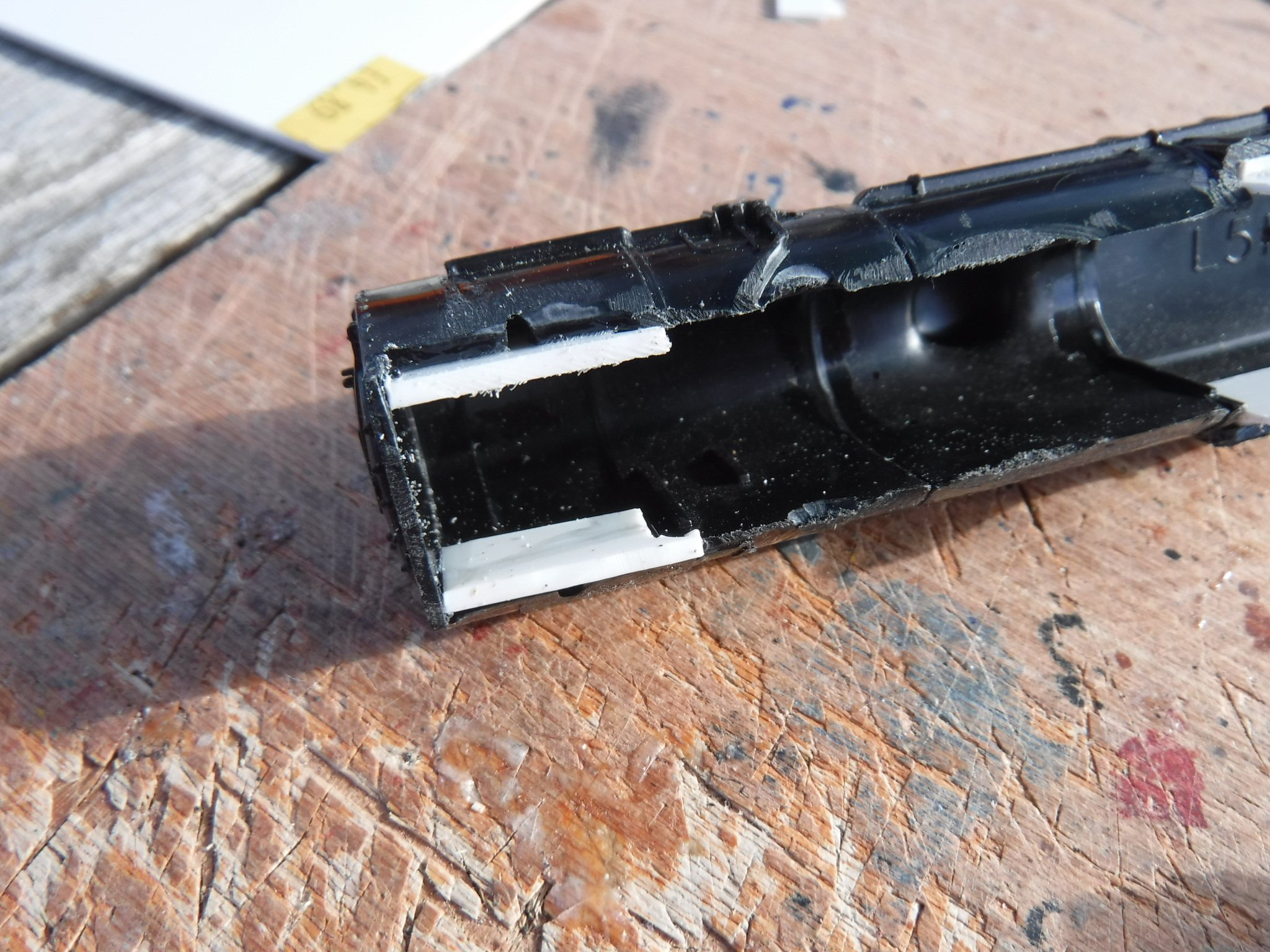
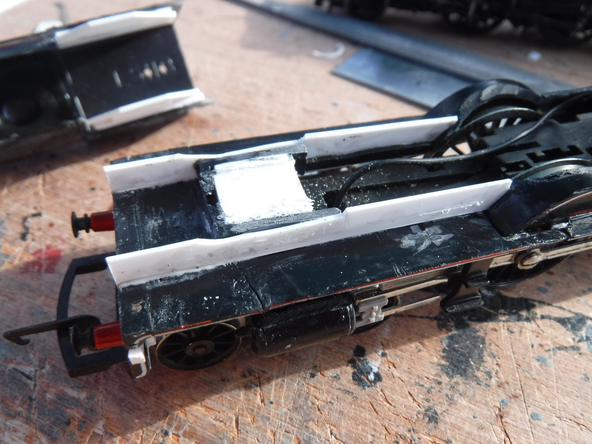
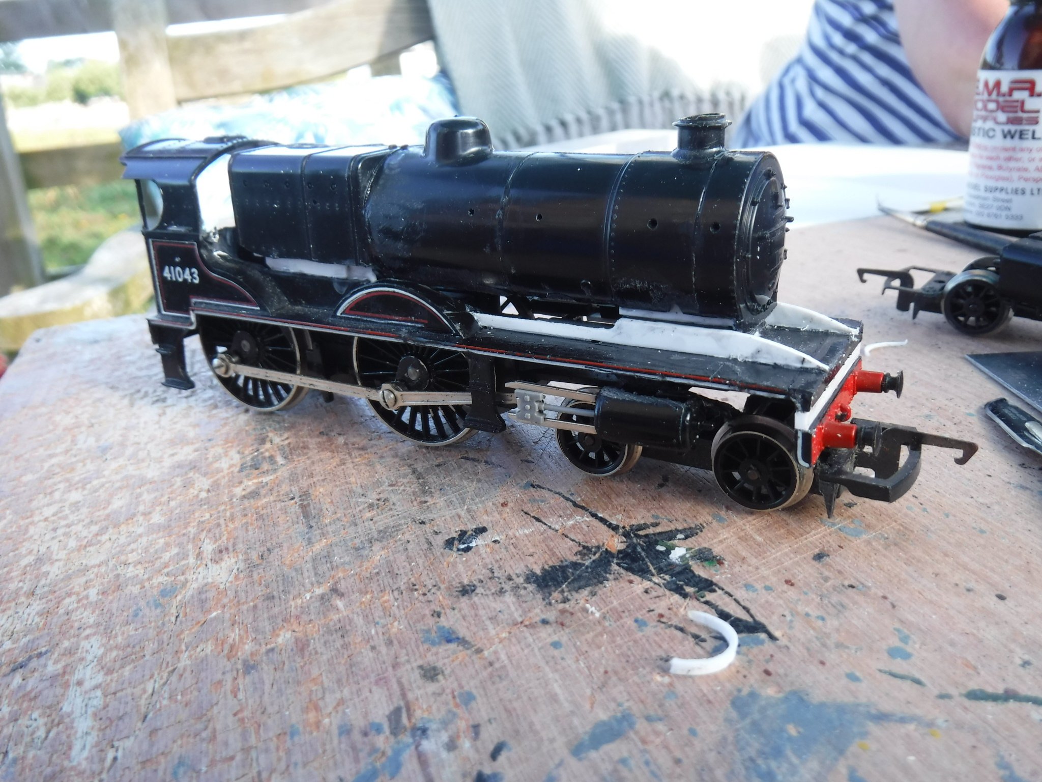
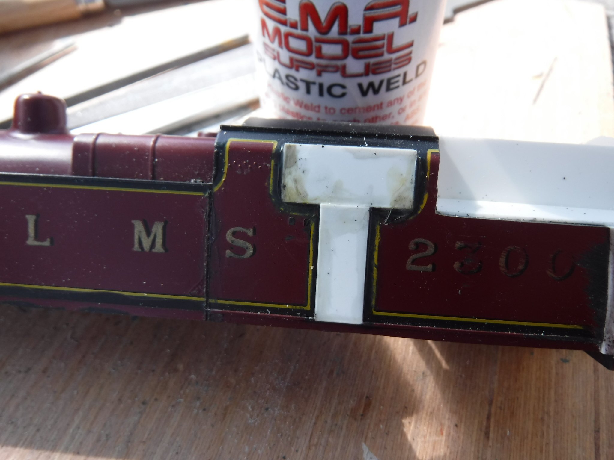
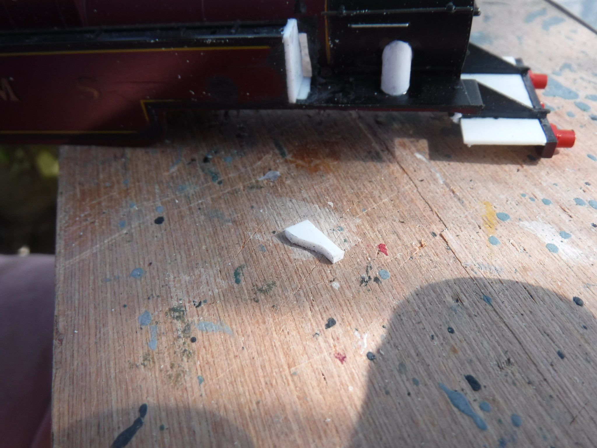
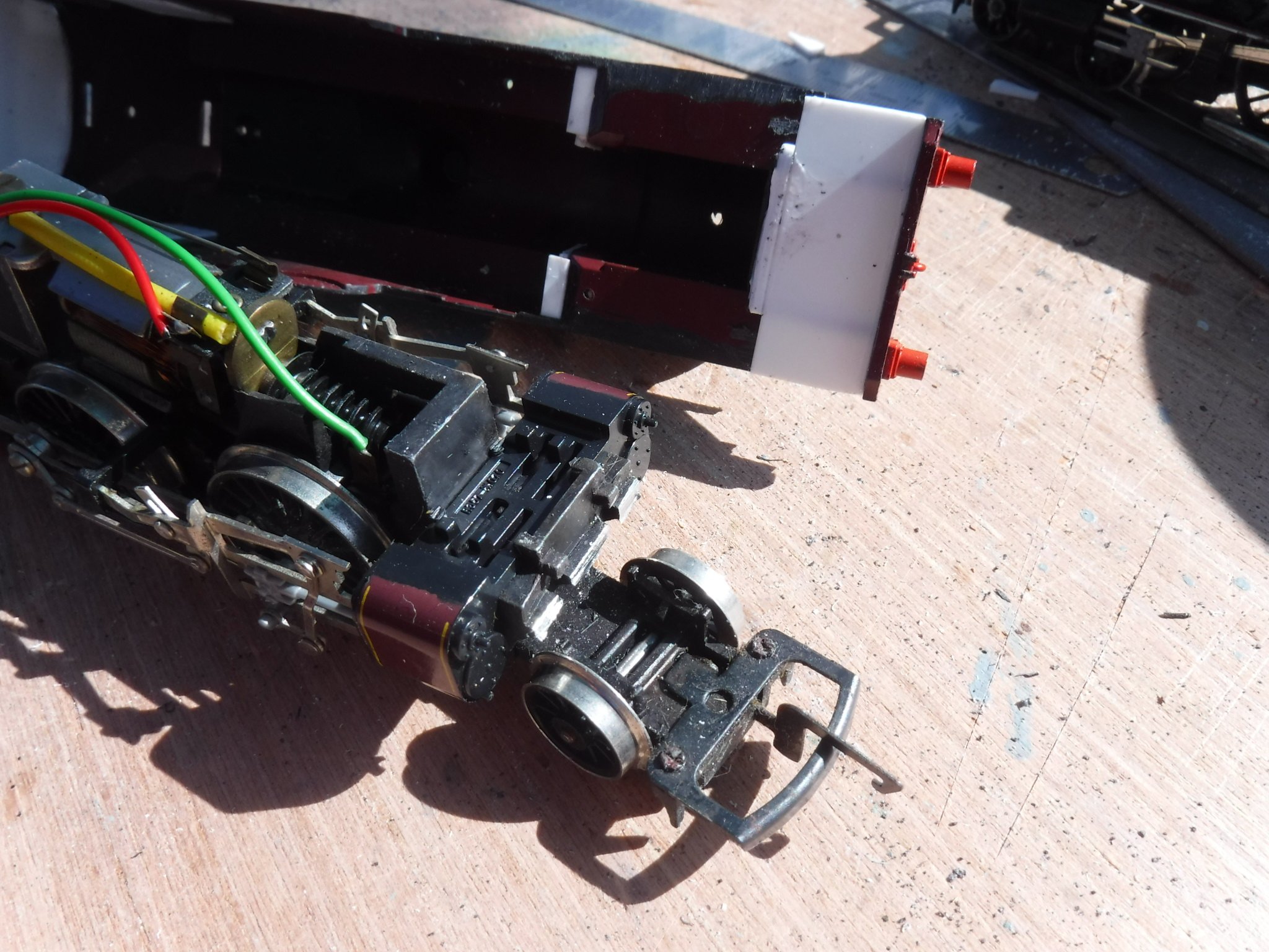
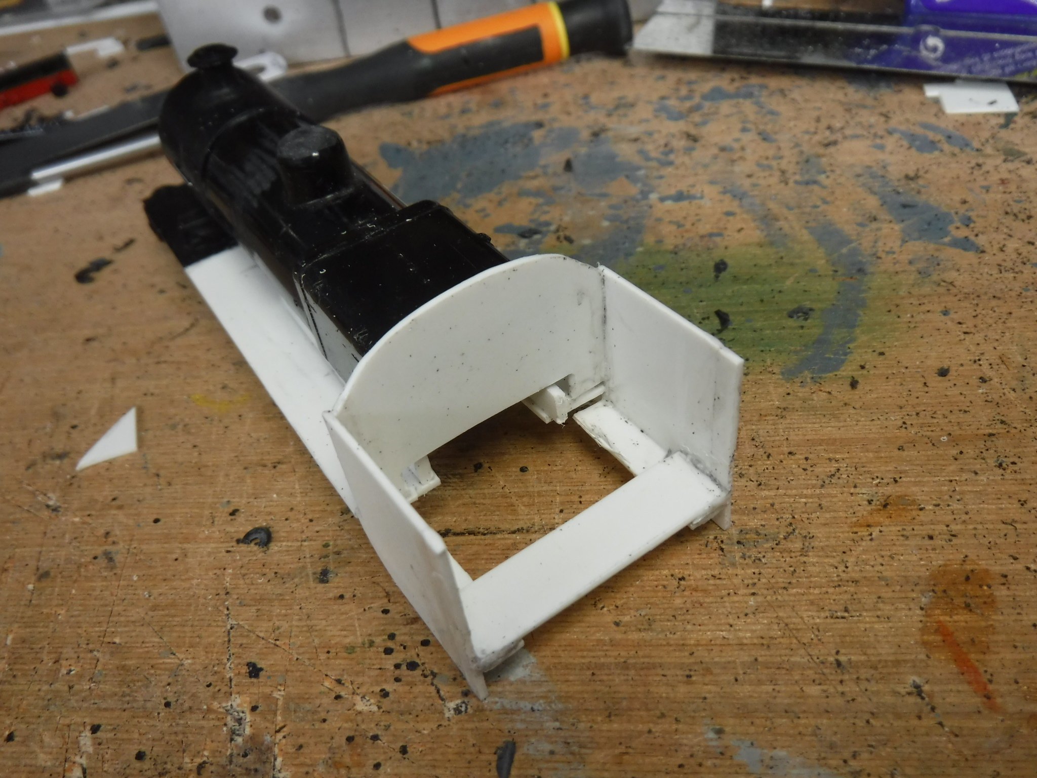
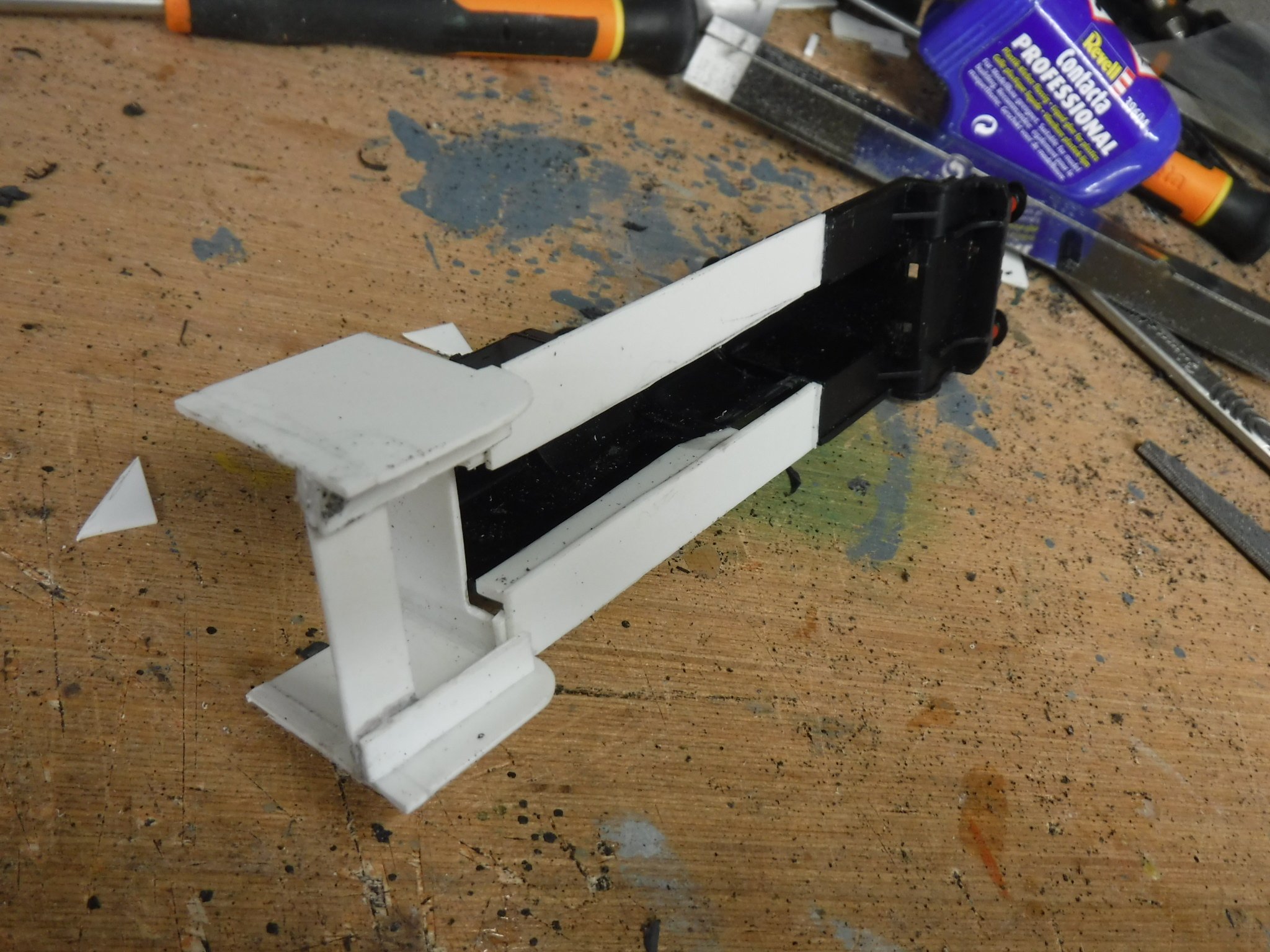
Hi Folks, Todays job was to shorten the tender chassis to make it a more appropriate length. The frames have been adapted to fit a standard Hornby motor unit and as such the wheel base is 48mm equally split, which scales at 6'-6' instead of 6'6"-6'6" as it should be 52mm equally split. The front edge to the leading axle centre is 3'6" and as such should be 14mm, the model being 17mm and the rear end to the trailing axle should be 2' 11" which for the sake of rounding up should be 12mm. I decided that the extra 3mm at the front would up to a point balance the 4mm missing between the wheels and left it alone also that the engine to tender coupling is in this area which would make electrical connection difficult. The fixed wheel base is precisely that, fixed and was left alone. This left the rear of the tender be dealt with. The first cut was immediately behind the rearmost spring link and then buffer beam-drag box area was removed by cutting above where the mounting clip is situated. There is a slight projection over the top of the mounting clip which I cut off and then later filed flat unlike is shewn above, freshly cut. I then cut away the tension lock hook attachments and filed the rear of the buffer beam flush. This was done so that the rear of the buffer beam could but up to the filed flat part above the mounting clip's location. Ignore the groove, that was just before a hasty change of plan and will be later filled-oops! The buffer beam and drag box was then offered up and scribed inline with the cuts immediately behind the spring links and the frames cut through and the lower part of the step removed. These edges were then offered up again and filed to fit so that both sides and the centre section above the mounting clip all engaged and that the whole assembly was both square and parallel. once this was achieved the sections were super glued together. Before reassembling the motor unit into the frames I filed the tapered lug at the end of the motor unit so that it would not put undue stress on the plastic structure when clipping it into place, this has not affected its ability to correctly locate but thought it necessary. The last job was to cut the weight down as it would have been to large and over hung the rear buffer beam. To mark out where the cut was to be I loosely attached the fixing screw and marked the weight in line with the locating lugs. It may have been better if my junior hacksaw had a sharp blade and that I had a vice to hold the weight in, hence the rather jaunty angle. My not brilliantly square cut, it does however fit. The result is I now have a tender frameset that is only 1mm over scale length rather than about mm. I say about 6mm because I didn't measure the rear end of the tender before starting the job so I can't say for certain although the off cuts are 5.5mm plus the kerf of the razor saw, so near enough 6mm. The wheel base is fixed unless a totally different mechanism is used and I' pleased with the result. The next job is to build the tender tank to the drawing supplied by Killian Kean. The only thing I'm unsure of is the tender bulkhead as I don't have a drawing of even photographs to work from. Gibbo.

-
Hi Folks, I have had a drawing sent by @Killian Keane via the Irish Steam Locomotive Tender thread that will assist me in building a far more accurate tender than what I may have achieved by way of scaling from photographs. Thanks for the drawing, Gibbo.
-
Hi Killian, Top man just what I was looking for. From looking at photographs I would say that the cab and the tender are of very similar width which is what I was going for with the model I am building right now. That said my model is actually .5mm wider than it should be but I can live with that. You should enter this image into the library in the resources section. Gibbo.
-
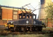
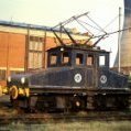
Hi Colin, This isn't a GS&WR enquiry, more a GNR enquiry. Does any one have a drawing of the type of tender that is trailed by GNR No.85 Merlin. I have a decent enough drawing of Merlin however only the front 25% or so of the tender is shewn so building one even nearly accurate will be difficult. If anyone can supply wheel centres and length over buffers I may be able to create something near enough by scaling from photographs. Cheers, Gibbo.
-
A 3d printed 800 class for 00 (and a WLWR goods loco)
gibbo675 replied to Killian Keane's topic in Irish Models
Hi Killian, With regard to the nut and bolt problem, would it be possible to use a small self tapping screw into a suitable sized hole within a boss on the underside of the print ? The reason I ask is that this is a method I use in my cut and shuts if a body shell requires fixing to a chassis. The old Mainline Scots were fixed in this way and they kept hold pretty well as are quite a lot of the Lima models. Gibbo. -
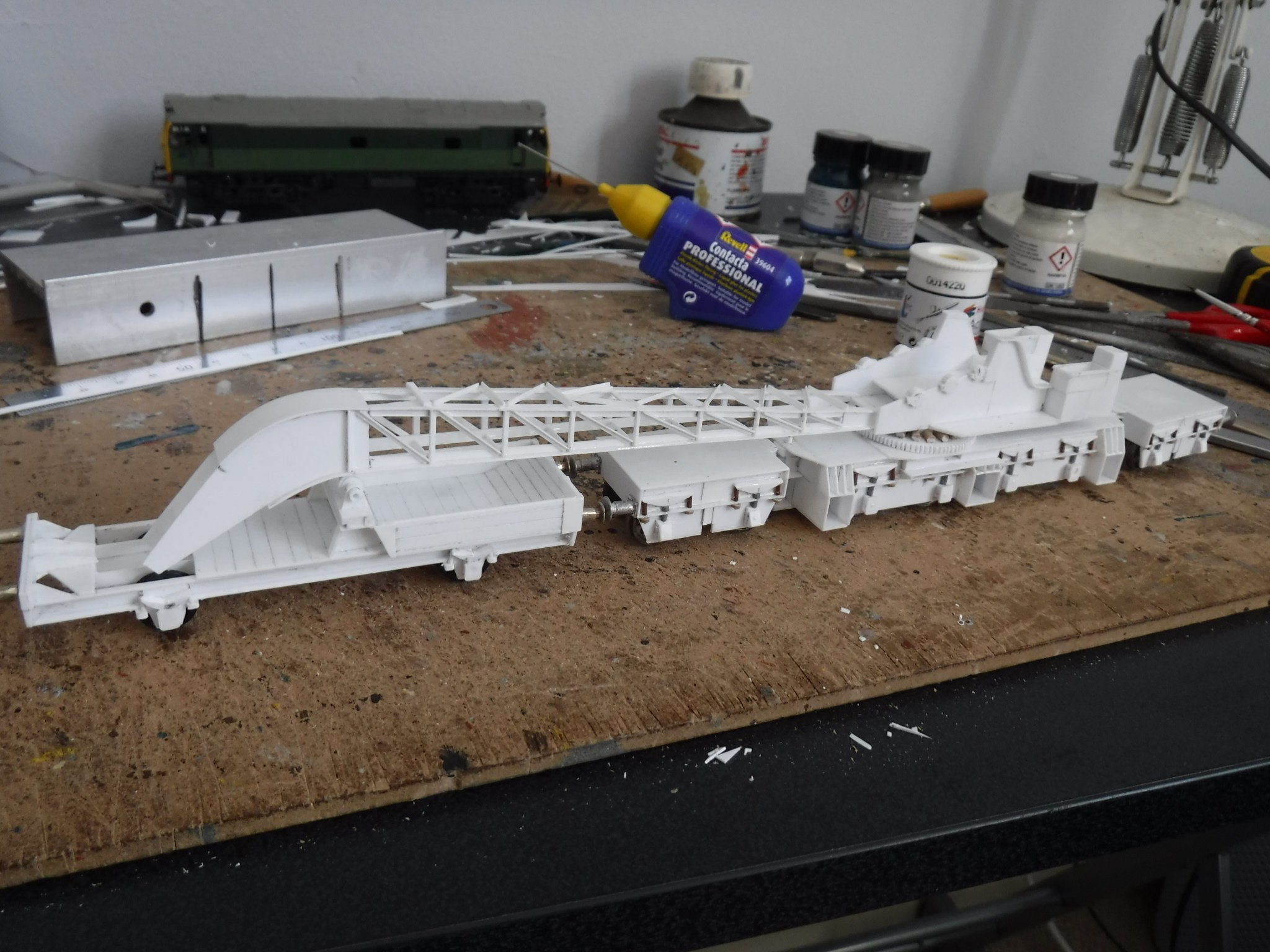
Hi Folks, As a diversion from normal service here is what happens when I acted upon my imagination. I thought it up, thought some more and then built it. It is nearly as daft as I am. Gibbo.
-
Hi David, Thoughts are articulated through the use of words, the use of words to describe what you wish for shews what is to be done to create you wishes. You are the creator in terms of subjective and objective realities, thus in a manner of speaking; "In the beginning are the words, and the words come from you, and the words are of you.". All I do is cut up bits of plastic and stick them back together again. Granted the bits of plastic I have cut up and stuck back together recently do look very much like small GNR V class steam locomotive, however that is all I do. There are two others on my other two threads, a NCC W class and a NNC WT class, just the same carry on. You could do it your self all you need is an eBay haul, some plasticard, glue, paints, transfers and some tools. You can follow my destuctions as shewn on this thread and then supply the rest yourself from within. Look and you will find it, it is called imagination, dust it off and away you will go. I shall be doing some sketch drawing of all the pieces soon enough so that this thread will form a guide should you wish to build your own. GET BUSY, ITS FUN AND ITS EASY [...ish] !!! Gibbo.
-
More a MAJICIAN, No. 85, Merlin. (arf arf !)
-
Hi Folks, You asked for it Patrick Davey, here it is ! I've been busy with the V class again, it has been cab and splashers today, The first job was cut the cab roof off just under the top of the D cutout of the cab side. There were two extensions to make the first was a 2mm deep shim that was glued onto the underside of the cut off cab roof and the second was a 1mm thick piece glued onto the front edge to make up where there would other wise be a gap to the spectacle plate. The shims along the undersides of the the cab roof were four pieces, two each side of .040" plasticard measuring 2mm X 22mm. The second was marked out by drawing around the cab roof stood on its end, the piece cut oversize so that it could be filed flush once cured. The shimmed up cab roof ready to be refitted into its new higher position. I then fitted a piece of .040" plasticard measuring 31mm X 25mm, when cured I fitted the cab roof butting it up and making sure that it was centrally placed. Once cured the spectacle plate is trimmed and filed flush to match the profile of the cab roof. The spectacle plate after being filed flush to the profile of the cab roof. The cab sides were cut from .040" measuring 31mm X 28mm I cut out to fit over the step in the running plate and also cut out a relief over the splasher. These are glued on and when cured the front edges around the spectacle plate and splasher may be trimmed back and filed flush. Cab side blanks one with the extra relief over the splasher, they were both reduce before fitting. The cab sides with the side sticking proud and also the front edge and splasher prior to shaping. I then cut out a piece of .030" for the cab roof this measured 30mm X 34mm. The 34mm dimension is over the width of the cab and once formed to ease fitting it will require trimming to finally fit it in between the cab side which will be sticking up slightly. Glue the cab roof on and once cured file the front flush with the spectacle plate, round the top of the cab sides to blend into the roof profile and trim the rear edge back to the original cab roof underneath. The cab roof may then be trimmed and filed to shape and the D cut outs and spectacle plate windows cut and filed to shape. I had a slight problem in that the shims should have been slightly longer and I had to make up some fill in pieces from .060" plasticard. This shews the bit that needed an extra piece, alternatively the shims could be made longer. The leading splashers also had a .040" piece of plasticard glued to their outer face to match the new width of the cab. Incidentally, the now wider cab better matches the somewhat chunky Hornby version of the Fowler tender which is rather more in keeping with the tenders trailed by the V class. I have been looking at the, "Irish steam locomotive tenders" by Colin R thread and have also had a most useful drawing sent by Flying Snail. The last structural job was to file down the cylinders by 1mm each side so that I could put a wrap made from 5/16" Plastruct tube around the the cylinders to beef them up, the Hornby ones looking a little slim. The Plastruct tube is 12mm long has a 5mm slot cut into it to allow it to slide over the mounting bracket. This photograph shows that measuring from the cylinder relief valve to the outside the dimension needs to be reduced by 1mm while keeping the round profile. The last job was to bog everything up with filler especially the gaps around the fire box so that it may be carved and sanded to shape once dried hard. Isn't filler great ?!?! Also shewing the enlarged cylinders. Gibbo.
- 51 replies
-
- 11
-

-

-
Hi Folks, One thing I forgot to request is, does anyone have a drawing of the tender types trailed by the V class locomotives ? As yet I haven't found one, the only detail I have is on the above locomotive drawing. Gibbo. Hi Mr Snail, Thanks for the compliments, I must tell you I don't usually model Irish subjects. My thing is the West Coast Main Line in Lancashire England circa 1974. so If you want more then you will have to put up with my usual rubbish.....British Rubbish though ! Gibbo.
-
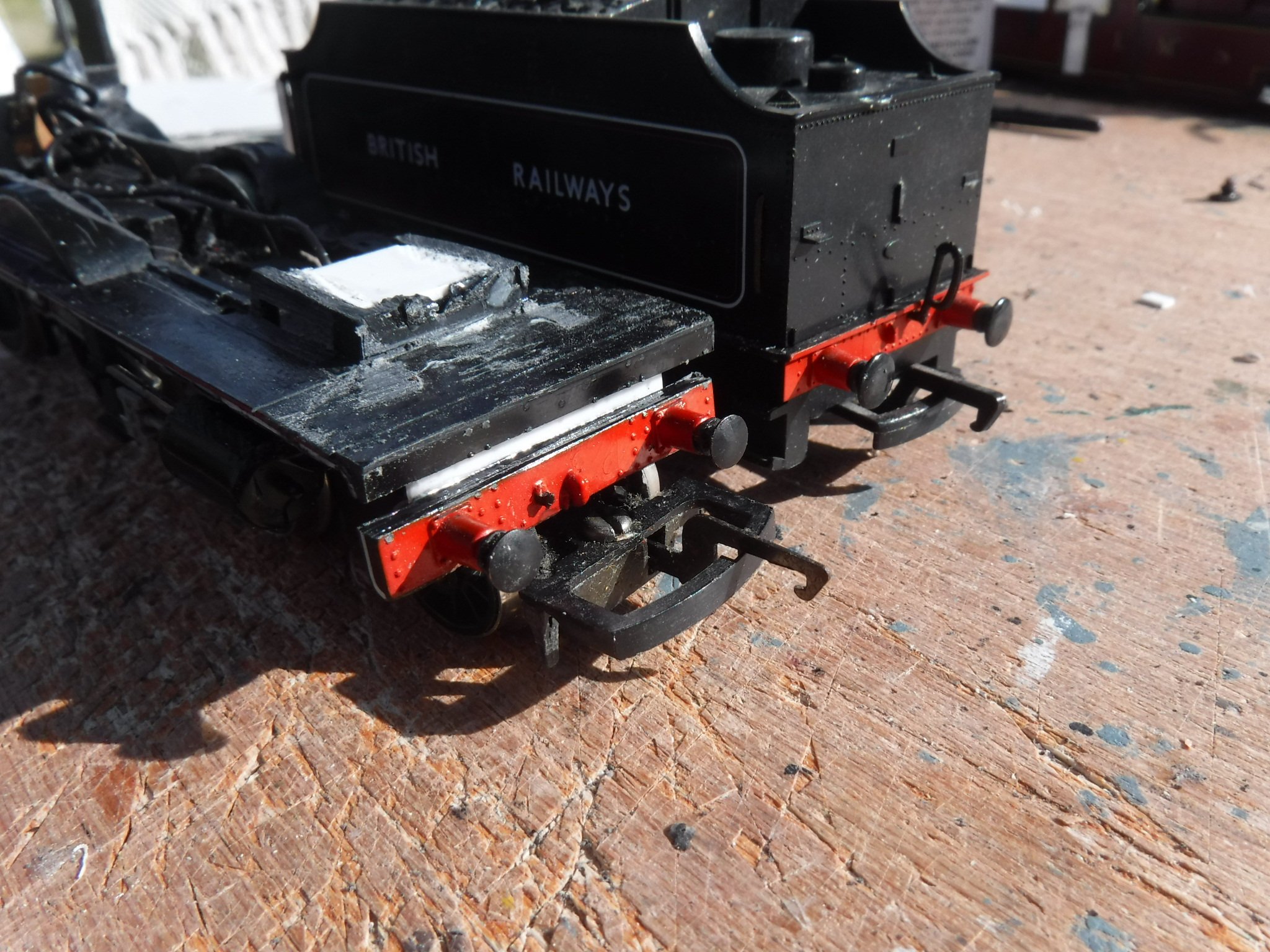
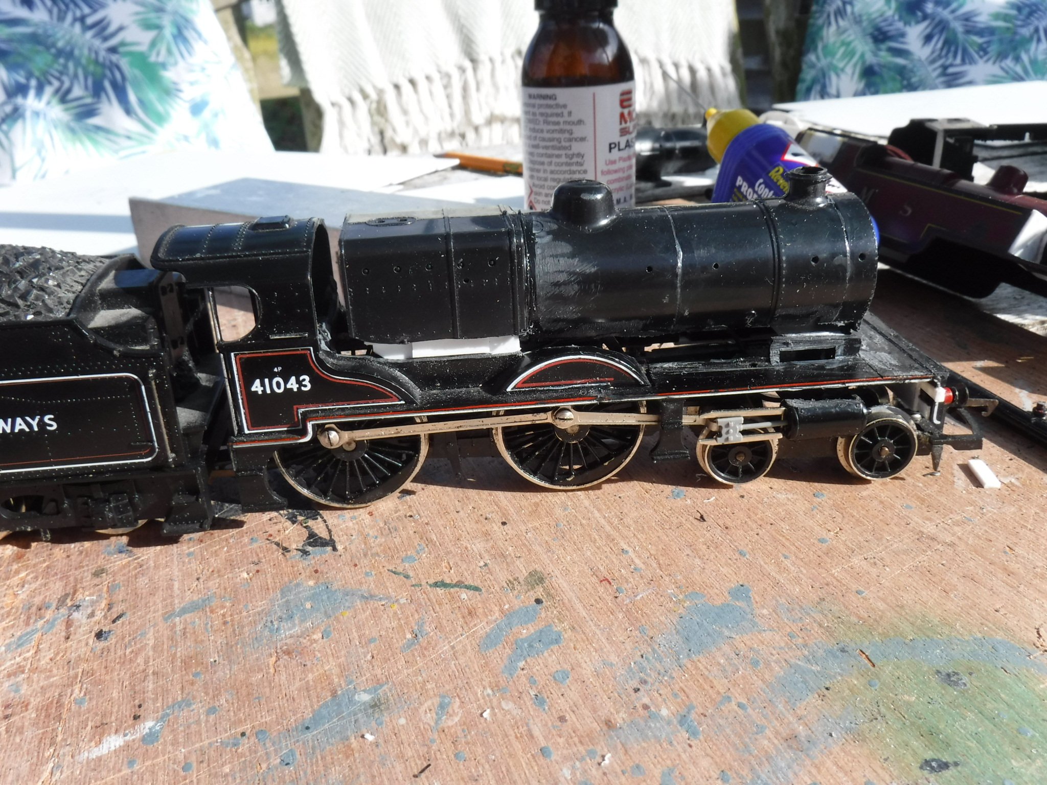
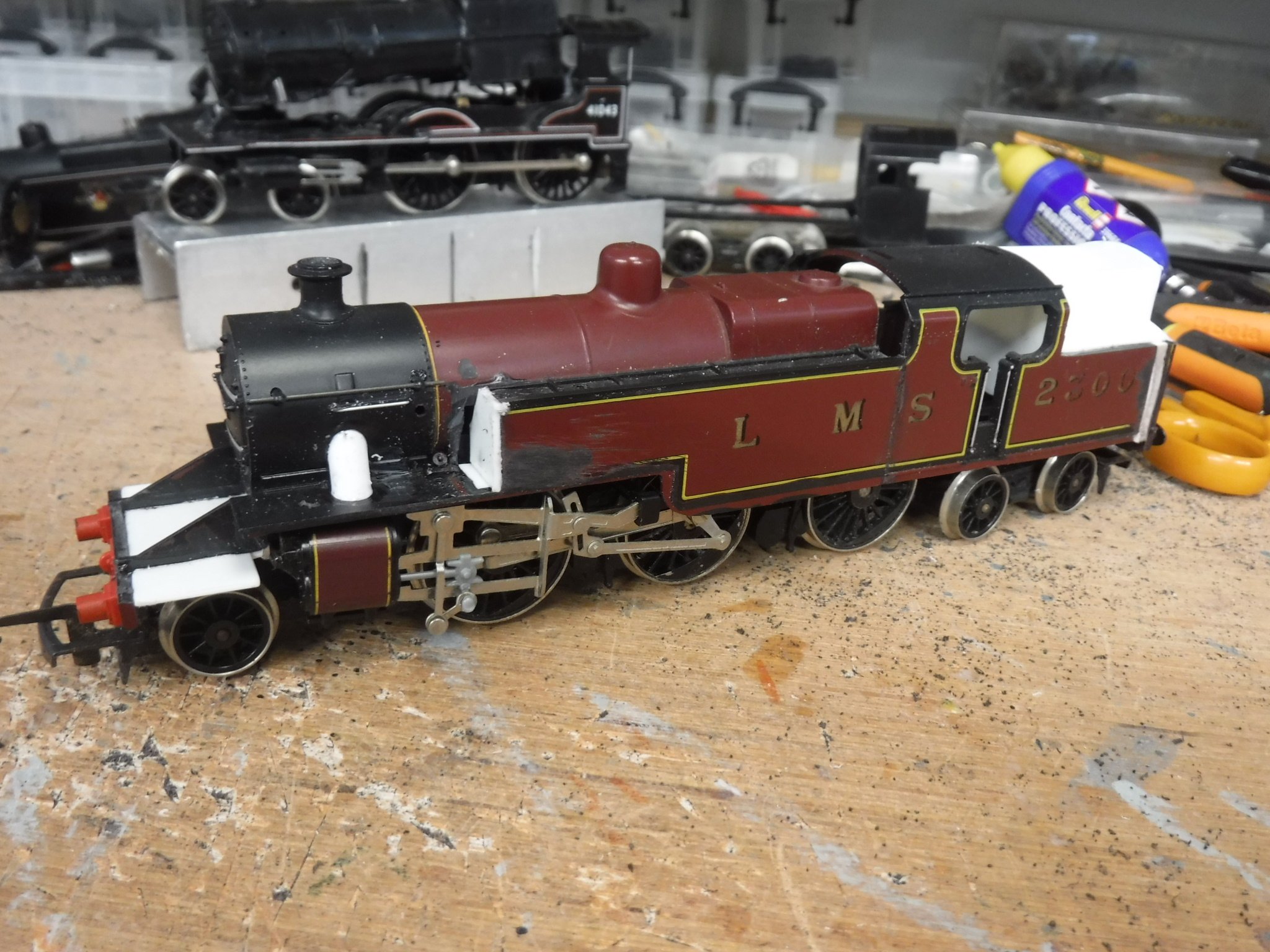
Hi Folks, I've been busy today the boiler has now been fitted to the V class along with the refitting of the buffer beam and the addition of the main frames under the smokebox. The first job was to refit the buffer beam I had cut the original off vertically along with the deep valance which in retrospect wasn't the best way to do things I perhaps should have just cut buffer beam itself off leaving the deep valance. No matter it has all worked out well enough. I glued a piece of .040"plasticard 8.5mm X 25mm under the running plates and to the front of the frames that go over the wheels. I then cut the buffer beam from the running plate valance. The latter was glued into place and the buffer beam itself was packed out with .030" pieces to provide a flat surface. The buffer beam was then glued onto the under side of the valance with a 2.5mm gap, I compared the height to the tender as reference. The gap was later filled with a 2.5mm piece of .060" plasticard. The 8.5mm X 25mm piece, it is not full width so that the buffer beam does not look too thick. The buffer beam glued into place next to the tender. The boiler was the next job with locating flitches glued onto the inner sides of the firebox, these were .030" 25mmX 15mm projecting down 10mm. The lower corners were cut back to clear the wheels. To the outer side of the flitches I glued a strip 2.5mm long to space the boiler height wise on top of the piece that was left between the splashers. Most conveniently the dimension between the slashers and the inner sides of the fire box are the same so the flitch plates fit very snugly. The spacers can be seen on the outer sides of the flitch plates. I next fitted some .060" plates to the inner sides of the smoke box I had these projecting 3mm. In test fitting the boiler they required filing to about 2.25mm so that when they sat upon the plate over the holding screw boss then the boiler sat level. The .060" smoke box saddle extensions. When I was happy that the boiler was in the correct position I made some frame extensions to sit atop the running plates I made these form 5mm strips of .030" plasticard and glued them in place. I filed down the appropriate height under where the smoke box sits and this turns out to be 3.5mm. Once the look was correct in regard to the boiler's placement I then cut and filed the shape into the frames before fitting the boiler. The frame extensions before cutting and filing to shape. The boiler fitted and glued into place. The chimney and dome have since been cut down and refitted so that the locomotive looks a little less tall. As you may see there is quite a gap between the cab and the firebox, this is the next job. Gibbo.
-
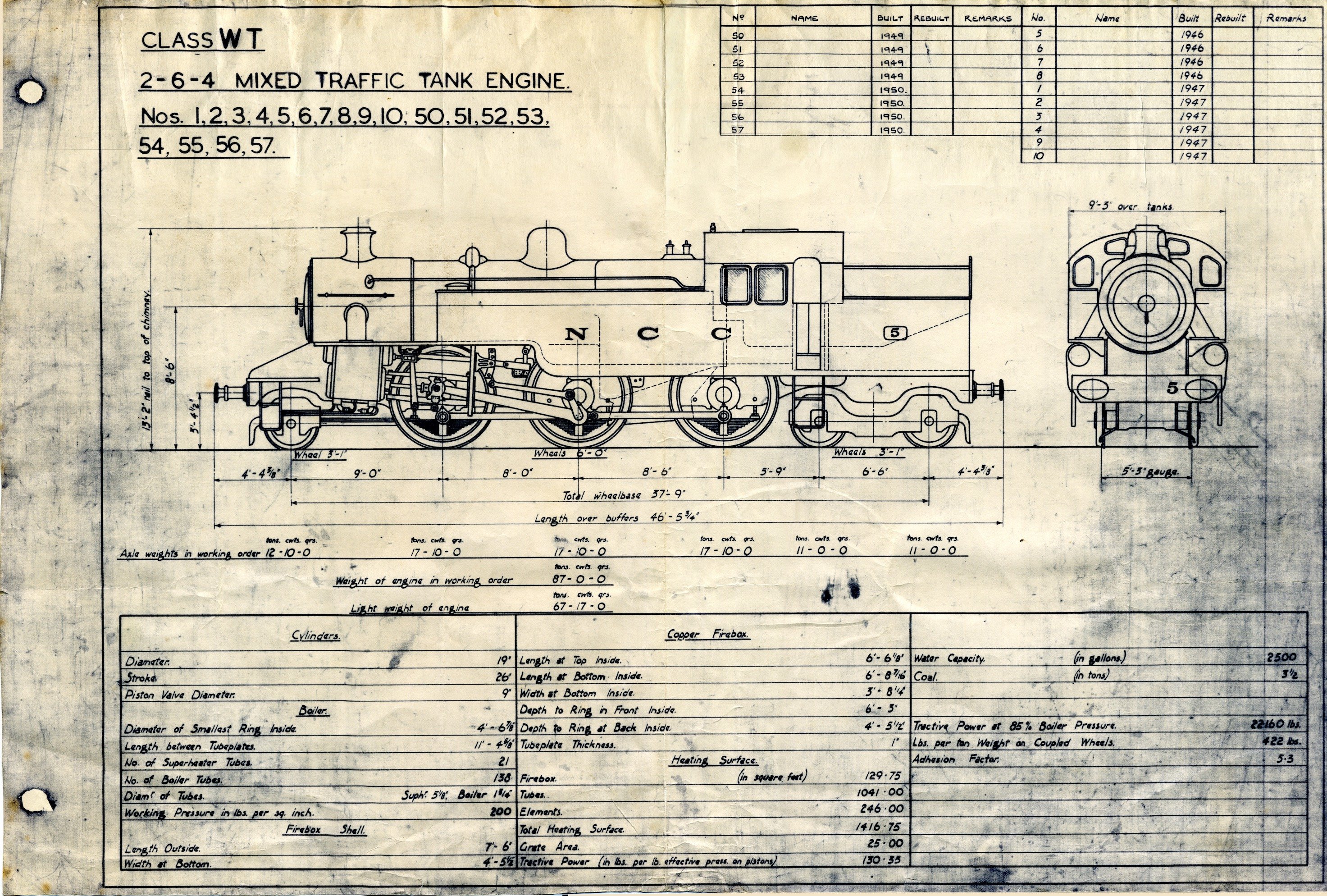
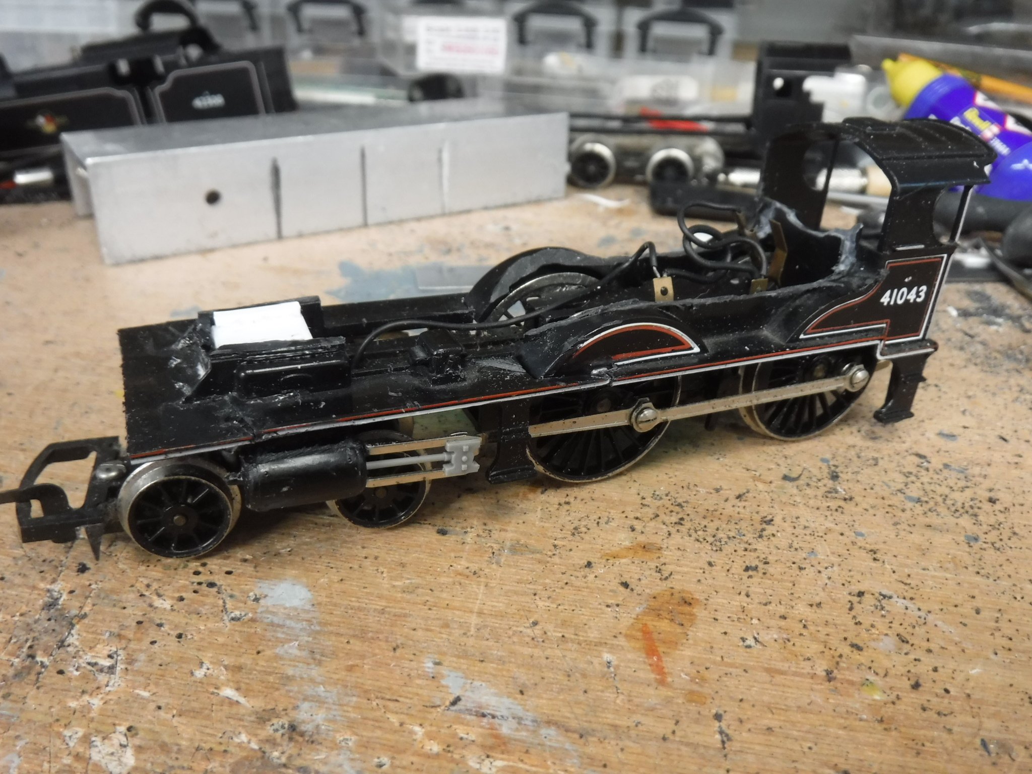
NCC WT class from Hornby LMS Fowler class 4, 2-6-4 tank
gibbo675 replied to gibbo675's topic in Irish Models
Hi Folks, I've done a bit more on the WT class today, better yet working at the table in the garden as it was pleasantly sunny. The job I did was to fil in the cab doorway and the D cut outs in the cab sides. To do this I first filed off the beading around the ends and lower edges of the D cutouts, I didn't file of the top edge as the curve of the cab roof means that there would be nothing much to attach to. Then the corners of the D cut outs square and then inlaid some .040" plasticard this was easy enough to do the pieces being 19mm X 8.75mm and filed to fit neatly. The cab doors had the handrails removed and scraped off the step block under the door way and again pieces of .040" 18mm X 17.5mm were filed to a neat fit and then the whole was glued in place. The cab D cut outs filed square. The filler pieces glued into place. I also filled in a little gap around the boiler where the tanks had been cut back, this job had not been done earlier as the sections that had been replaced were still a little soft from gluing at the time. A small fillet of .060" plasticard was cut and shaped to fit into the gap. The filler piece ahead of the tanks. A detail that I hadn't noted from the previous piece was that the lip at the front of the chassis under the locating lugs requires removing so that the running plates under the smokebox fits up to the chassis correctly. The removed lip and the small fillet that makes up under the smokebox. Gibbo.
-
Under Gibbons, that's me !
-
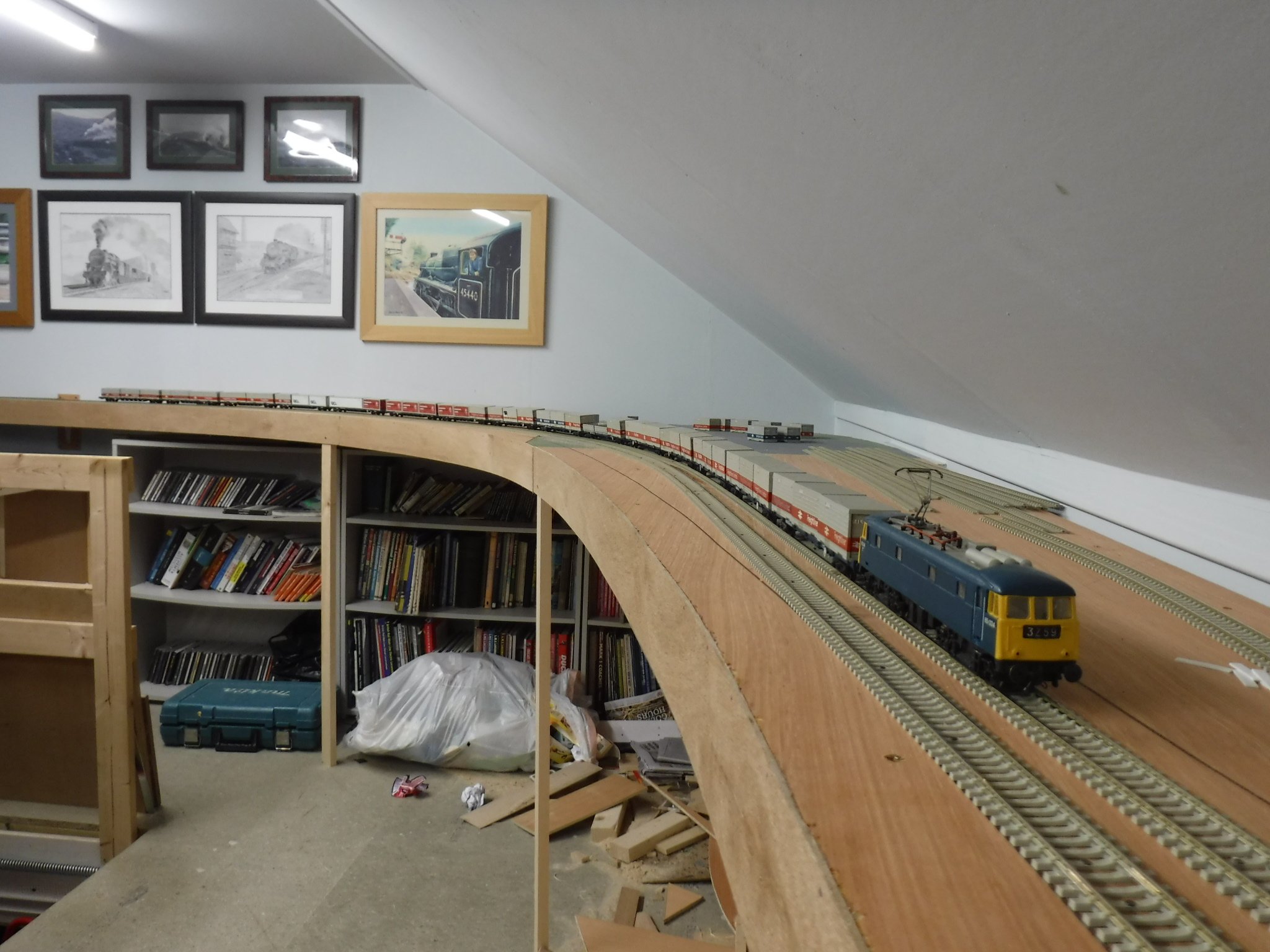
Hello Mr Darius, Its good to see that you still do things properly, unlike like me who generally cuts, shuts, codges and bodges ! I've finished my Freightliner train and at fifteen bogies some of my locomotives will pull it but mostly double headed roarers. I haven't sorted out the BP container tanks you sent the decals for yet, they ended up in the nearly started box along with all sorts of other stuff. As you may note the layout is a work in progress. I shall have a good look at your thread and no doubt be asking some questions about certain of your projects. Gibbo.
-
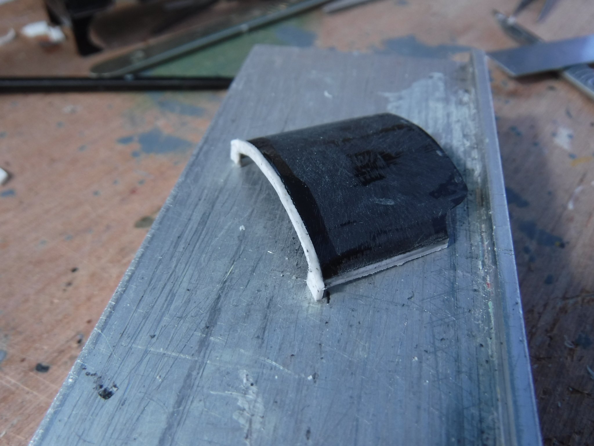
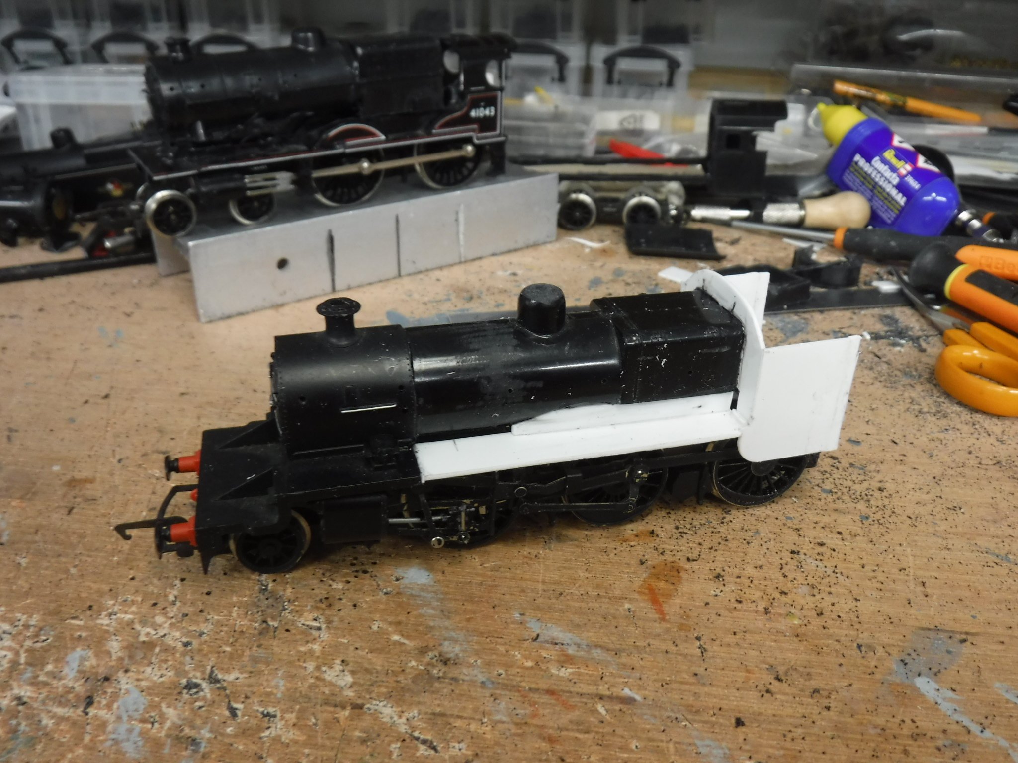
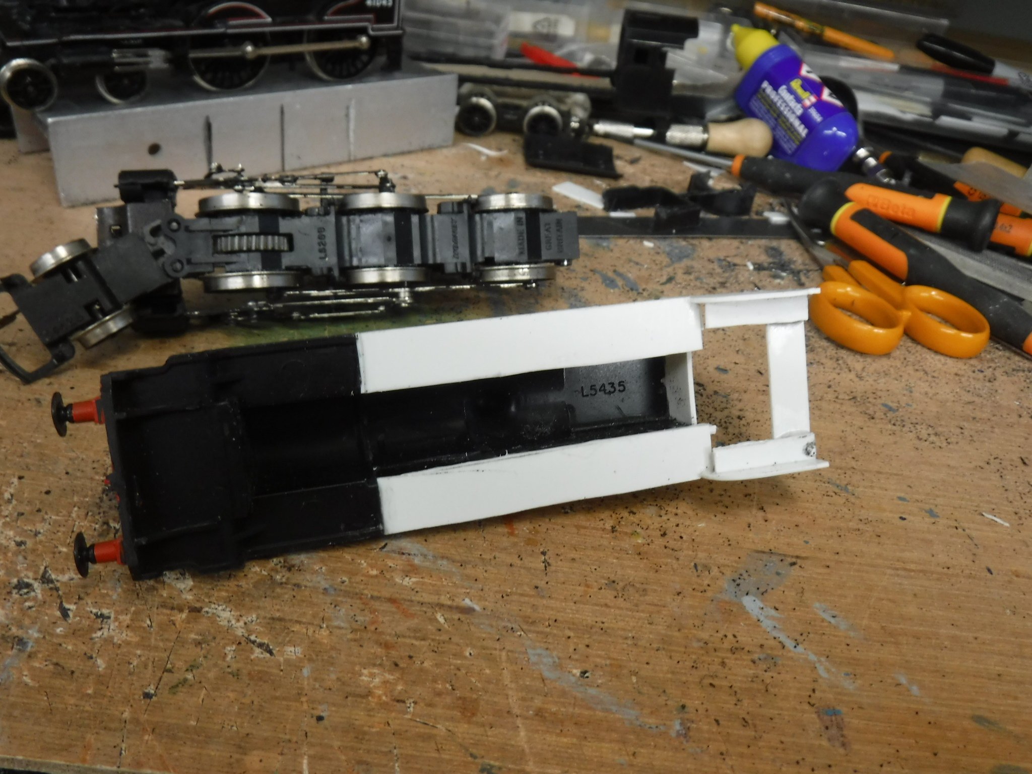
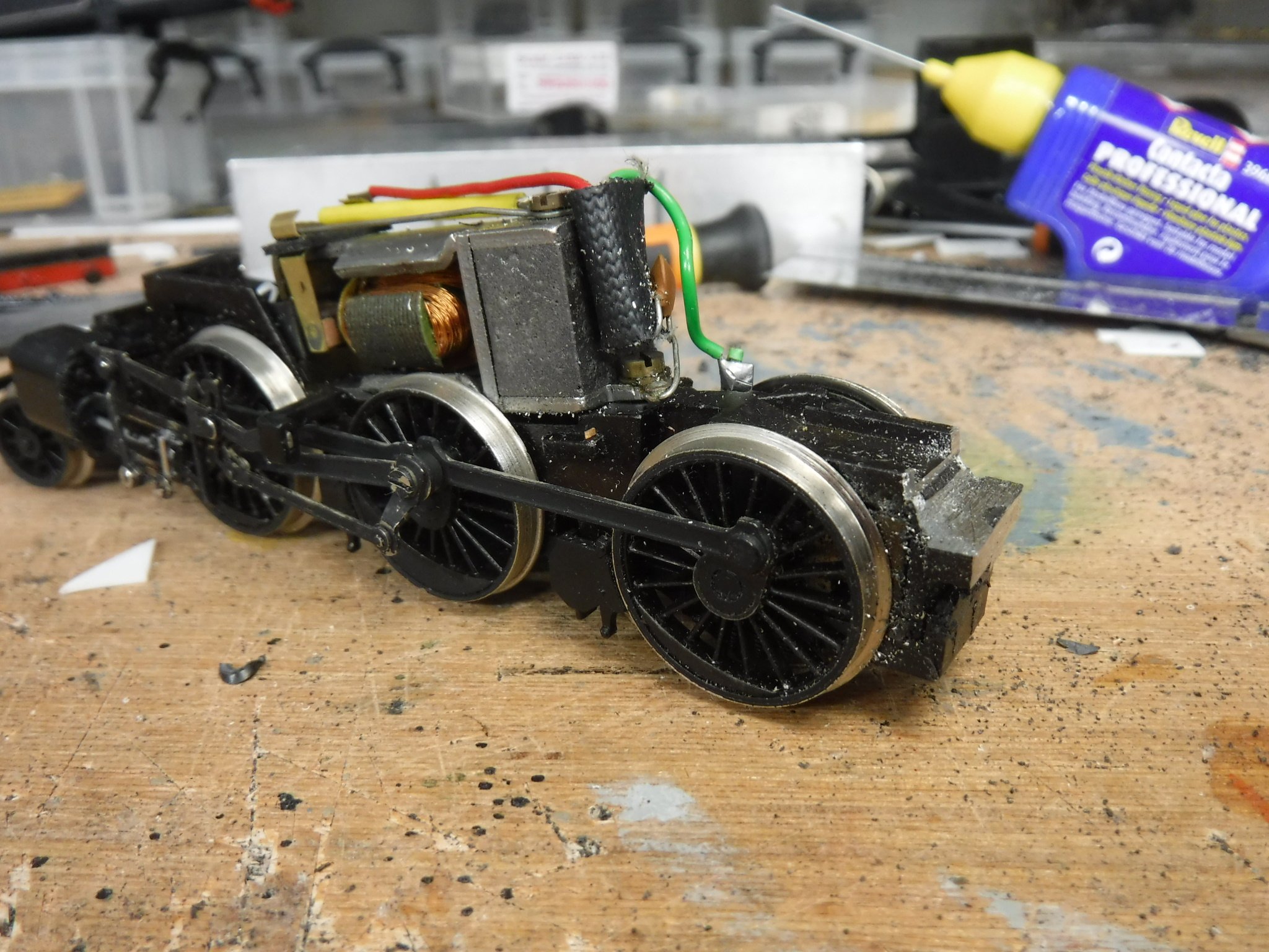
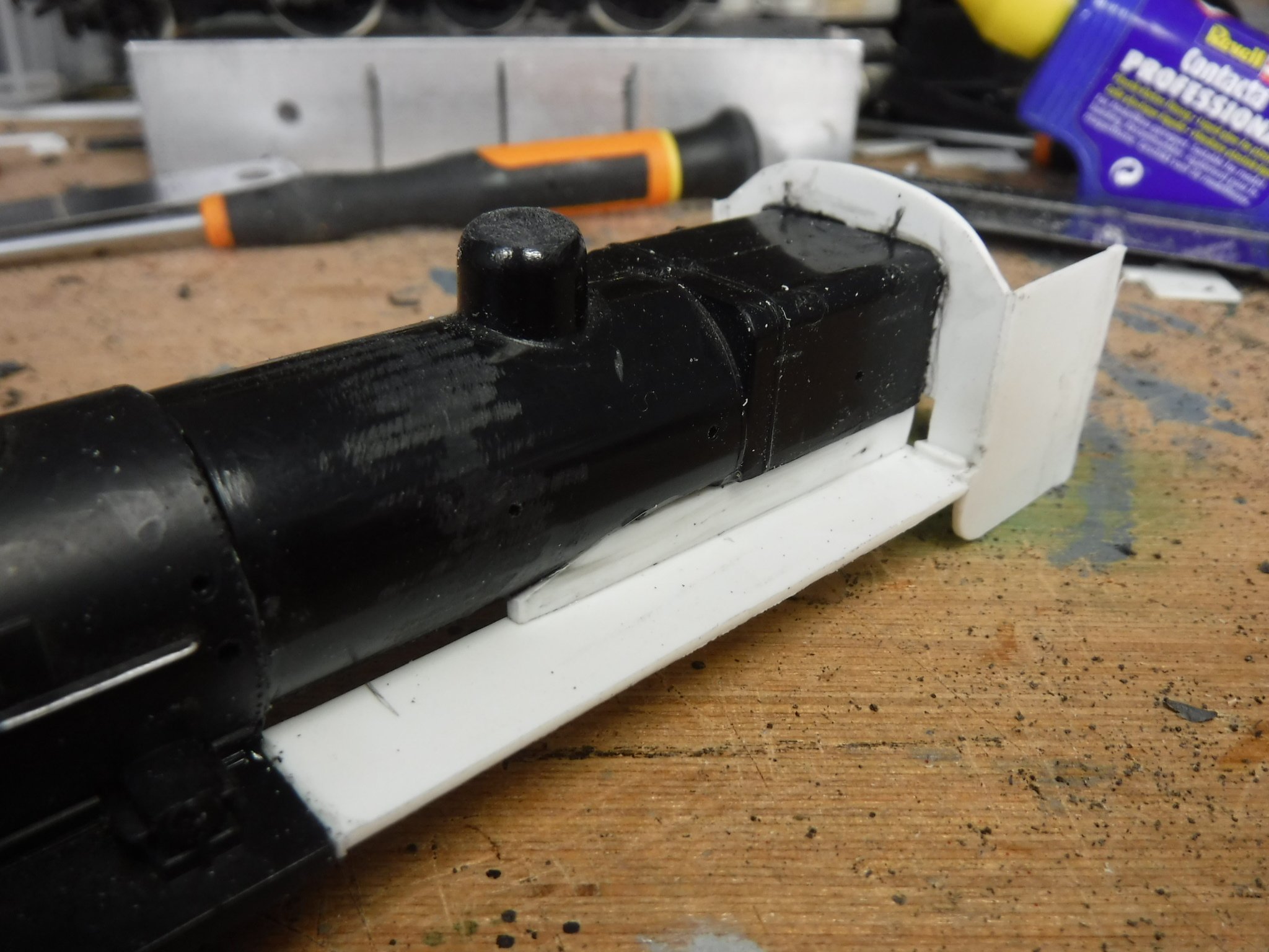
Hi Folks, This thread is to run in conjunction with my other two as the three will compliment each other as far as types go and the parts bin special way that I cut and shut models. The chassis is fairly easy although quite brutal as the rear end is chopped off including the bogie just behind the rear wheels I filed a flat so that the cab floor would sit upon it being carful not to take out too much as there is a pocket for a magnet that must be left with some strength to it. The cuts to the body is as severe for the tanks and boiler were cut from the smoke box and won't be used any further as I used the boiler from the Midland Compound that was spare from the V class. The first thing I did was to cut the compound's smoke box from the boiler and then attached the boiler to the tank engines smoke box. The barrel length from the shoulder of the fire box to the rear of the smokebox measures 44mm the same as the Fowler tank, which makes things easy. The rear of the fire box is then trimmed back so that its total length is 25 mm the same as the WT tank. I then made up was the cab sides and spectacle plate from .040" plasticard, I shall produces a sketch drawings in the next post. This was then attached to the rear of the firebox and left to cure ready for the next job which were the running plates. these were made from 11mm X 71mm .040" plasticard which were trimmed and notched to fit into the front of the cab. I then made extensions to fill the gap between the lower cut edge of the fire box and the boiler, these will be suitably laminated and carved back to shape to give the form of the lower firebox and the underside of the boiler. Gibbo.
- 12 replies
-
- 12
-
-
-

-
Cheers Chaps, Thanks for the welcome, I'm new to Irish railways, with lots to learn. I'm more of a West Coast Main Line circa 1974 being originally from Lancashire, I can remember the changing of diesels to electric locomotives at Preston and. What I do like like is a good cut and shut though as it is a good way of creating both something quite different and also what is generally unavailable. I have various ideas for cut and shut coaches which I shall get on with once the locomotives are complete. Gibbo. Gibbo.
-
NCC WT class from Hornby LMS Fowler class 4, 2-6-4 tank
gibbo675 replied to gibbo675's topic in Irish Models
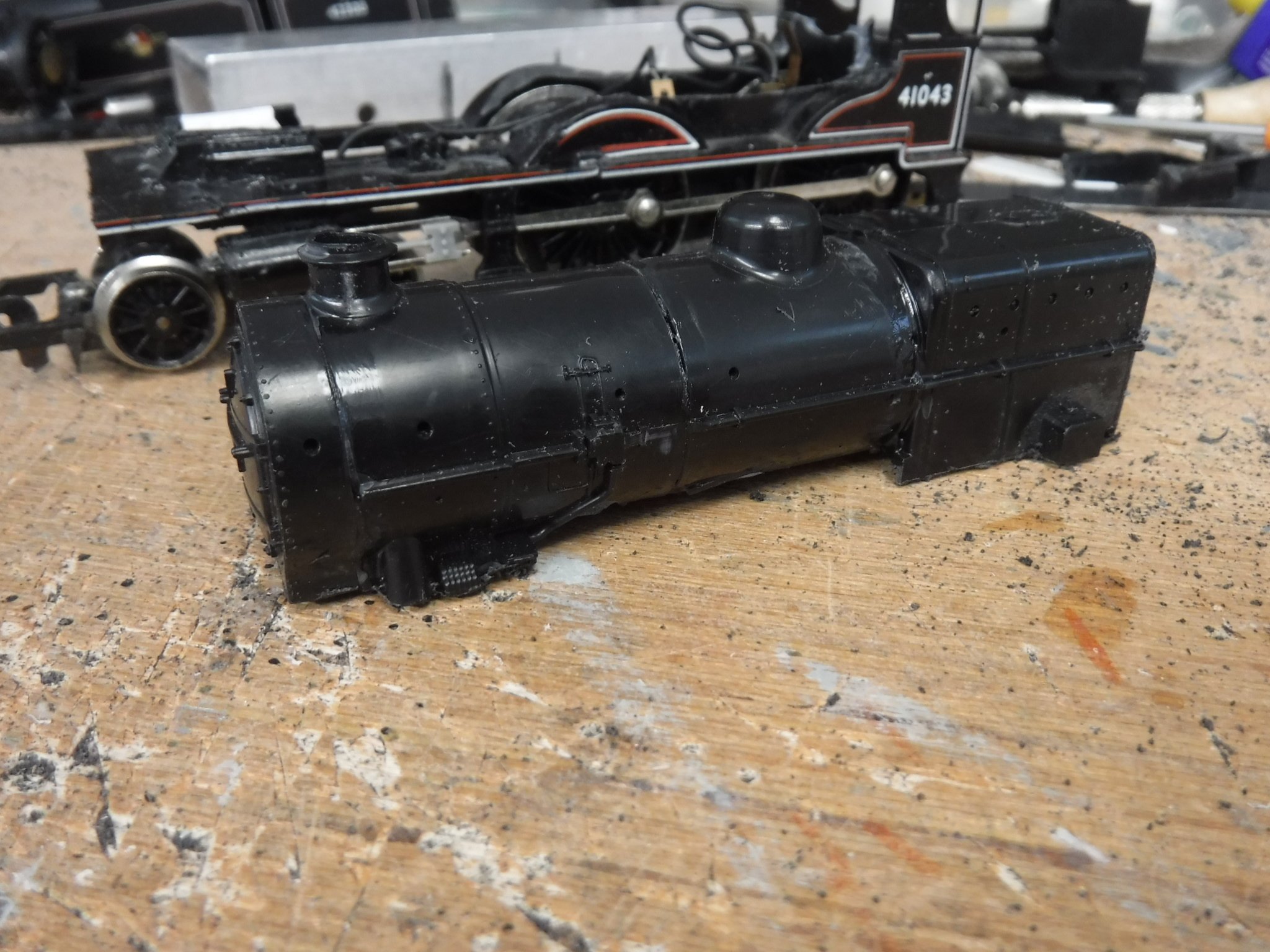
Hi There, Wait until I've finished, that way I can make all the mistakes ! Gibbo. Hi There, Just the very thing, I was happy with using the other drawing with photographic reference regarding the lower edge of the tanks. Cheers, Gibbo. -
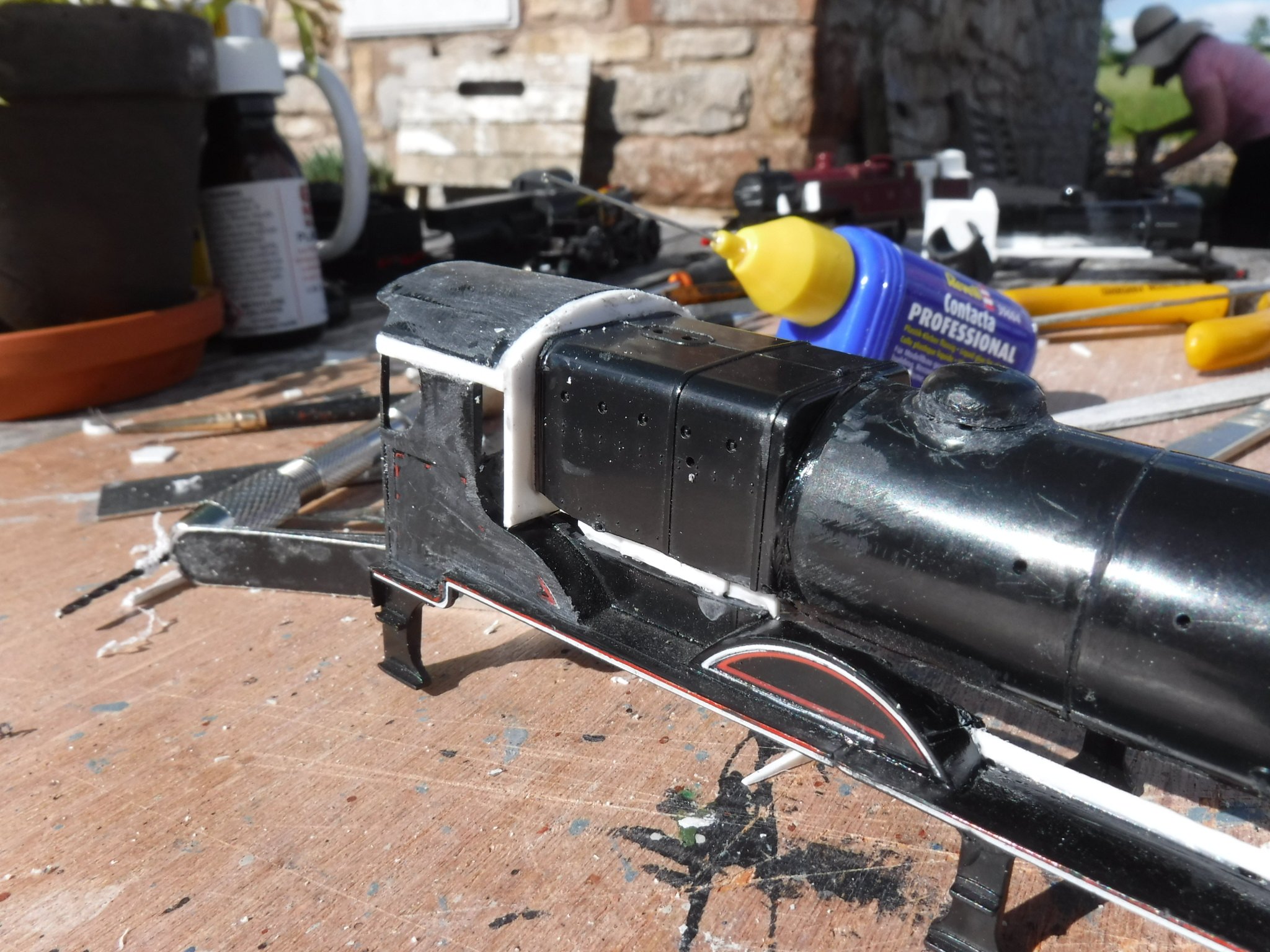
Hi Folks, This thread involves the building of a WT class form the Hornby Fowler class 4 tank locomotive. The chassis is pretty close although the bogie under the cab requires to be moved forward by 3mm and the rear bracket that the body fixing screw requires removing other than that it is good. Body shell wise: The front running plates require modification The tanks require cutting back by 3mm The bunker lengthened by 3mm The cab shortened by 3mm The boiler shortened by 3mm I stated by cutting out the running boards leaving just the mainframes and the buffer beam. With a bit of careful filing I managed to fit into place a piece of .040" plasticard under the main frames that finished flush with the top of the buffer beam. this measured 33.5mm X 14mm. In altering the tanks I cut off 4mm from the front of the tanks so that when the new piece of .040" was glued in place the front edge would be in the correct position. These pieces were 10.5mm X 13mm so that they stood proud and could be filed flush later on, I also cut a corner off so that they would fit in but that was done to suit. The cab section was removed and I cut down the sides of the tanks in line with the front of the cab simply removing 3mm. When all filed up and square it was all glued back together. The bunker required a lot more chopping about, the rear of the bunker was cut off completely as was the coal. Don't worry too much about keeping the cuts square as all that is required are spacing pieces which were three pieces of .040" cut to 22mm X 2mm. I fixed these to the ends of the bunker sides and left them to cure. Once cured I filed them flush and then refitted the back of the bunker. The top edge of the bunker was finished to 19mm from the lower edge, I then fitted a horizontal stiffener and a rear spectacle plate. The spectacle plate needs to finish 24 mm from the underside of the cab roof to clear the chassis. The inset sides of the bunker were then fitted to the horizontal stiffener these measure 12mm X 29mm and then a piece 34mm X 15mm is used for the upper section of the rear of the bunker all three form .040" plasticard. Do check the measurements to your own work should you choose this method. The sloping sides were then made from specially fitted pieces of .030" packed up against the inset sides on 1mm wide strips of .030", these were cut at 7mm X 29mm and then filed to fit as they are slightly tapered. I made steam pipes from 3/16" Plastruct tube cut and filed to shape, the lubricators require removing first though. Gibbo.
-
Hi Folks, I'm new on here and this is my first post so do let me know if it is the correct category. I am building some steam locomotives for a friend of mine in Sligo as he doesn't have many Irish outline models, so far his only Irish locomotive is a Silver Fox C Class diesel I built for him a couple of years ago. After looking at various photographs and finding some drawings here and there on line, this site included I decided to build him a GNR V class, a NCC W class and a NCC WT class. All three are from Hornby models that are being variously cut and shut to make them more accurate and while I'm at it sharing what I shall be doing should it be of any use to those on this site. This thread will be for the GNR V class and I shall create threads for the other two locomotive types soon enough so do look out for them also. The basis for this conversion is the Hornby Midland Compound which as far as it goes is very close in leading dimension and looks except that the boiler is too small and the cab is not as deep front to back. Having had a look at the drawing I found on line, I figured that the boiler from a Hornby LMS Patriot was about the right diameter and decided that splicing that onto the compound and altering the running boards that would be fairly close. The boiler was cut off and set to one side as it was to be used for the W class. The cuts being directly behind the smokebox, along the firebox 5mm above the running boards and around the line where the splashers meet the boiler barrel and also cutting down the front of the cab spectacle plate. The running boards were then cut where there is the small joggle by the leading splasher by cutting the splasher from the running board with a razor saw horizontally. The buffer beam was then cut from the forward section of the running board and the lug with the thread insert was cut out from under the smoke box. The smoke box saddle was trimmed for height at the level of the rectangular boxes at sides and then the running boards were glued rear section so that they are in a straight line. Once all that was cured I refitted the lug with the threaded insert back onto the chassis and filled it so that the cab and running boards sat level and parallel to the rails and glued it into place I also fitted a piece of .040" plasticard over the top of it to reinforce the lug. The Patriot boiler was cut either side of the boiler band just ahead of the dome, I did this to get a cut square tot he axis of the boiler and then glued that back together. This reduced the distance form the chimney to the dome to pretty much the correct dimension. I then cut section out of the smoke box just ahead of the chimney so that when replaced the smoke box measured 18mm. The firebox was cut off just ahead of the boiler band and the rear section was shortened so that the distance between the front edge of the fire box and the rear of the smoke box measured 44mm. The fire box is pretty much the correct length along with the rest of the boiler and so far I have left it alone until I see how the modified cab will line up. Gibbo.
- 51 replies
-
- 16
-