

Junctionmad
-
Posts
1,136 -
Joined
-
Last visited
-
Days Won
1
Content Type
Profiles
Forums
Resource Library
Events
Gallery
Blogs
Store
Community Map
Posts posted by Junctionmad
-
-
if you stay in 00 gauge and bullhead you have the option of
(a) PECO new bullhead track , quite nice , even if the chair detail is somewhat generic , code 75 nickel silver
(b) C&L , two types , original with thin sleepers , and FASTTRAK which has an exactoscale think sleeper base, nice chair detail , code 75 nickel silver
© SMP plastic sleeper , thin sleeper base, code 75 nickel silver ,
(d) DCC Concepts , code 75 stainless steel , thick sleeper
AT present none of these companies can supply ready to lay points, so you have either to wait for PECO ( but only one type of point ) or build points for scratch or kits
Note that , I posted a review of C&L and DCC on here somewhere , personally I wont touch stainless steel track , far to hard to work and requires specialist fluxes and solders ( why DCC bothered is beyond me )
certainly of the MSWR sections of CIE , right up till recently ( 2010) there were siding still in light weight flat bottom track , this could be modelled with PECO code 65 flat bottom, simply glued to ply sleepers , at present there no solution for the CIE chair that was sometimes used under the FB rail ( cant speak about the GNR )
-
When setting out the Goods Yard at Omagh my plan is to take the original engineers drawings that I have and overlay it with an imaginary grid which will give me references for the exact point positions and from this run centre lines through the pointwork and track that I can transfer to the actual baseboards. Sounds complicated but I think it will work.
The only issue with that is you are likely to need compression in a model layout, personally Id take one of the many layout design software apps and build by layout in that first , to see what the ultimate dimensions are
-
I totally agree with you regarding exhibition layouts, a friend of mind built a station called Chelfham on the 2ft gauge Lynton and Barnstaple Railway in North Devon, you could not get a simpler layout, a passing loop and one siding and it is a fantastic model, boring as hell to operate at an exhibition, yet when it was working, there was always three or four deep just to watch the trains pass by.
For me, my idea layout would be based on one of the American shunting puzzle designs, but it would incorporate a continuous run as well.
I know when I was little there was nothing better that watching trains go pass at speed, either in real life or on a model railway. Why is it we always wanted it to crash?
Good luck with Claremorris, if I had the room that would be one layout I would build as part of a team effort.
thanks re Claremorris, its a big undertaking , but I'm a builder as much as an operator and its a interesting challenge , using 00-SF I can at least run off the shelf plain track etc
-
I also realise that over time track plans where modified to make them more simple and easier to maintain, one thing I have noticed with a few Irish track plans, is the use of a siding coming off the middle of a loop on one side and crossing the other track of the loop via a diamond crossing and then going on to serve a good shed behind the loop.
its not a track formation , I can say was common in ireland, most single line stations were very simply " tracked " with the goods siding typically in advance or in the rear of the station and primarily designed to be accessed in the direction of the majority of traffic , typically " from " Dublin etc . Land was comparatively cheap in ireland and many stations were quite sprawling, presenting challenges in model form
The formation you mention is more common on double lines, where the B of T rules frowned on facing points , so one line had to cross the other to access the yard. IN recent years the use of facing points is less frowned upon and such complexities are largely gone
-
Building the track is not a problem, I have in the past built both points and track in a number of gauges, what I was thinking about was more of a time saver if you could find someone else to do it for you.
Great, getting handmade track built cheaply isnt a reasonable assumption, its time consuming work, and hence relatively expensive, suck it up as the americans say
 Most layouts I see at exhibitions have a very simple design and consist of a run round loop with a number of sidings off of it, it is getting harder to find layouts that for want of a better reason are a bit more of challenge to operate or to view. To me, it would appear that some of the more complicated but interesting track layouts fail to get modelled.
This is a perennial issue for exhibition layouts ( and one my club finds difficult to resolve ) . challenging layouts by definition are " challenging " and at exhibitions , punters want to see trains running ( if you have ever manned an exhibition layout, its interesting to see how fast people drift off, when no stock is moving ) . Hence layout that require shunting, cross track movements etc are likely (a) to need multiple operators ( b) more likely to stall or derail and (b) often dont hold the publics interest
My club is currently deciding to build far more complex ( in comparison ) exhibition layouts , one that will inevitably require multiple operators and will work to signals etc. But its a big undertaking
Home layouts , where there is nothing to prove , is where you find much more complexity
o me, it would appear that some of the more complicated but interesting track layouts fail to get modelled.SO im in the early stages of modelling claremorris in the 70s , 50 points , 5 single line junctions, massively signalled to support " knock " specials ( 10 passengers trains in the station at one time !) and also the attached ballinrobe branch ( which I have committed to exhibit next easter, --- gulp , just the branch mind you )
but without huge amounts of automation, running this whole layout at exhibitions will require 3-6 operators , a very big commitment
In my case I actively sought out a complex track plan, and its the reason I'm doing it in 00 , because in anything else , there is not a hope Id complete it inside 10 years . Most layouts in ireland that are complex, are simply too big to model , and applying huge compression, results in an untenable layout. Then again most track work in ireland , even in steam days , was relatively simple, with few uses of complex ladders and slips etc , unlike what was common in the UK ( where traffic densities where orders of magnitude higher )
Railway modelling is full of " biting off more then you can chew ", people massively underrate the time it takes to build a good quality layout, especially where there is any complexity
-
I was under the impression that these items are already available through the P4 Society?
Here is what is available , whats missing is a check rail gauge , arguably the most useful gauge
95A Track gauge, Type 'A', Rollergauge - 5' 3" Gauge (21 mm) �5.20 1
190A Track gauge, triangular, for automatic gauge widening - 5' 3" gauge (21 mm) �9.50 1
( thats your three-point gauge you were looking for )
RSGA Roger Sander's 'Mint' gauge for fine tuning pointwork - 5' 3" gauge (21 mm
also these standard gauges are useful
192 Flangeway gauge �4.50 1
DDW01 Block gauge with crossing alignment aid (DD Wheelwrights)
In my experience, its was the need to build large amounts of plain track, that put me off 21mm, the pointwork is the fastest side of track building, constructing and laying " miles" of plain track inc fiddle yards etc , is what put me off
Again the only difference between 21 to EM as opposed to P4 standards , is the wider flange-ways and the point blades have to have a wider gap when open. Everything else is the same. back to back are then eased over P4, which helps to reduce running radius
-
Hi Tony
I spoke to the new owner of C&L Trackwork yesterday at an Exhibition and we both agreed that while a custom built 21mm gauge point might be say 25-35% more than an off the shelf Peco point, you just can't get that look any cheaper.
To be fair this is one of the reasons why I have found it so hard to get started with 21mm gauge, I have been quoted silly money in the past for hand built point work, but if you can find someone who can make a decent point at a reasonable price then other factors need to come in to the equation, such as will it save me time? It is one less problem to consider, we are not all good at everything in modelling, sometimes it is good to get others involved with our projects.
The guy at C&L who has just taken over, said that there are a lot of old computer files he has not looked at yet so they may be something in there, he appears to be very helpful and I guess it will be a two way development if he is to help us get 21mm gauge templates at some stage.
He did suggest for the short term that we could buy his P4 point work kits and then adjust them to 21mm gauge.
What we need now is someone to make 21mm gauge: roller gauges, back to back gauges and the tri gauge for curves as well and I am sure it will become much easier.
While it is early day, I did find him very helpful.
I build my own point work for my Irish layout in 00-SF. There would be no cost difference in pricing in a 21mm point. depending on what level of details ( chairs etc ) , a handbuilt point is cheaper then a PECO large radius point. This is , of course, building it yourself.
Secondly I would suggest that you consider building your own track work, Humbly,I suggest, If you dont have the engineering skills to build a point ( which is a simple process ), then I suspect you will find converting stock equally challenging
PS there is no need to buy c&L points kits, the sleeper lengths will be wrong anyway. Nor do you need to source templates Simply print a correct 21mm template from Templot, and then if you wish you can use C&L pre-made switch blades ( 16 quid a pair ) and buy their crossing Vees etc. However if you can use a file ( and buy the Scalefour filing jigs) then you can make your own in about 30 minutes.
Templot templates are much more accurate anyway then the the Societies or C&L templates , some of which have suffered from scaling errors over the years
If you dont have a background in this , then dont jump until you understand all the compromises
Note that no-one makes a check rail gauge for 21mm to EM standards ( nor do they make it for 21mm P4 i think ) ( which is more the pity ) , if you go 21mm to p4 standards , beware of the implications for rolling stock , the quality of track work and laying it etc
Note that roller gauges can be easily made from bolts and washers etc and verified by a micrometer, and you can easily build 3 point gauges with some judicious filing
you need a track gauge , a flange check gauge and a flange way slim to build a point, a 3 point gauge is useful for laying plain track
p4 is a world away from PECO , in order to get it running well.
-
Thanks Tony,
I was not aware of all the bits available via the Scale4 Society thanks for bring me up to date.
On RMWeb I asked the same question and some one has offered to buy the gauges I am after which inmy case will be the curved gauge widening three point gauge and there is another I have asked him to get me as well, just need to wait for a reply and the cost of postage for them.
could I suggest you join the society , its cheap and very useful no matter what 4mm gauge you model in
-
I wonder why people insist on using 21mm gauge with EM wheelsets. EM wheels are noticeably wider than prototype so if you use them, the distance over the wheel faces is overlarge. That means loco splashers,valve gear, w-irons, bogies and other stuff often have to be wider than prototype, which looks as wrong as the wrong gauge. Better to model an EM version of 21mm gauge, which would be 20mm or slightly more, depending on how precise you want to be.
Everyone seems to focus on the gauge as being sacrosanct, but in reality I think you need to balance gauge against other factors to get the best balance.
This isnt quite correct, the slightly wider modern EM wheels will have little effect on loco dimensions , valve gear and splashers etc are not effected. Nor is there any reason to reduce the gauge to simply model in 21mm to EM flange ways. Its all about the crossing flange ways
-
Could I make a plea to remember to photograph the infrastructure, signals , small stuff in yards, building etc.
This is typically stuff that's bulldozed with little record , whereas we have zillions of loco pics.
Thanks everyone that takes a photo
-
Consideration could be given to modelling 21mm to EM flangeway standards, this would allow radius down to about 2'10 and hence could get round in a 6' shed, it also removes the need to compensate locos and wagons , EM has 1mm flangeways as opposed to 0.68mm for p4. 00 style wheel set on longer axles can then be used and trackwork is a little more forgiving
Visually, you then have 21mm but running models is a little easier and less precise
You'd need custom track gauges, but that's not that difficult to make etc
-
Visited the Gauge O guild premier show today. Well worth a visit, a real " builders " show with loads of traders and obscure ones at that.
Venue was excelant too
-
I would rate the proxxon as well better then the dremel having had both. The Proxxon is smother and better made
-
Actually there's still a few in use between Waterford and Belview
I find that strange as abbey is closed AFAIK , and the line is run under engineer possession , effectively one engine in steam, which doesn't require signalling
-
All these free sites should carry a health warning
" warning , you will be ultimately screwed "
When will Flickr follow ?
Anyway rip photobucket , how to kill your business in one " easy " decision
-
just a follow up
shows a galway train with a TPO and its one BSGV hooked up at the top of the Galway train , proof that on occasion older stock got attached to Mk2 trains
-
fo those that are still interested , As Im doing the conversions , I keep coming across BSGV photos
I think originally this list came from Glenderg
3172 former BR BCK 21138
3173 former BR BCK 21146
3174 former BR BSK 21143
3175 former BR BSK 21196
3177 former BR BSK 34227
3178 former BR BSK 34590 was also air brake through piped
3179 former BR BSK 34677 was also air brake through piped
3180 former BR BSK 34378 was also air brake through piped
3183 former BR BSK 34687 was also air brake through piped
3184 former BR BSK 34566
3185 former BR BSK 34093
3186 former BR BSK 34757 was also air brake through piped
3187 former BR BSK 34012 was also air brake through piped
3188 former BR BSK 34701 was also air brake through piped
3189 former BR BSK 34264 was also air brake through piped
but I can confirm that 3174 is a conversion from aa BCK and not a BSK ( there is a picture of 3173 ) in the fred dean flickr albums
note according to Doyle and Hirsh
3171 to 3176 , 6 vehicles were all converted from BCK Mk 1 stock and 3177 to 3192 were from mk1 BSK
-
The main issues around NEM pockets is two fold
One is it's a HO standard and this has lead to 4mmmanufacturers making incorrect assumptions.
Secondly ,00 rtr manufactures have either by error or by wilfull decision have misplaced the pocket
In the US No manufacturer would buck the NMRA standards without good reason. But 00 rtr has suffered from weak standards. Even though the Double O Gauge Association has issued a NEM pockets standard for 00, this organisation is largely ignored.
-
Reading the resources on kadees , I don't believe the NEM versions are a solution
-
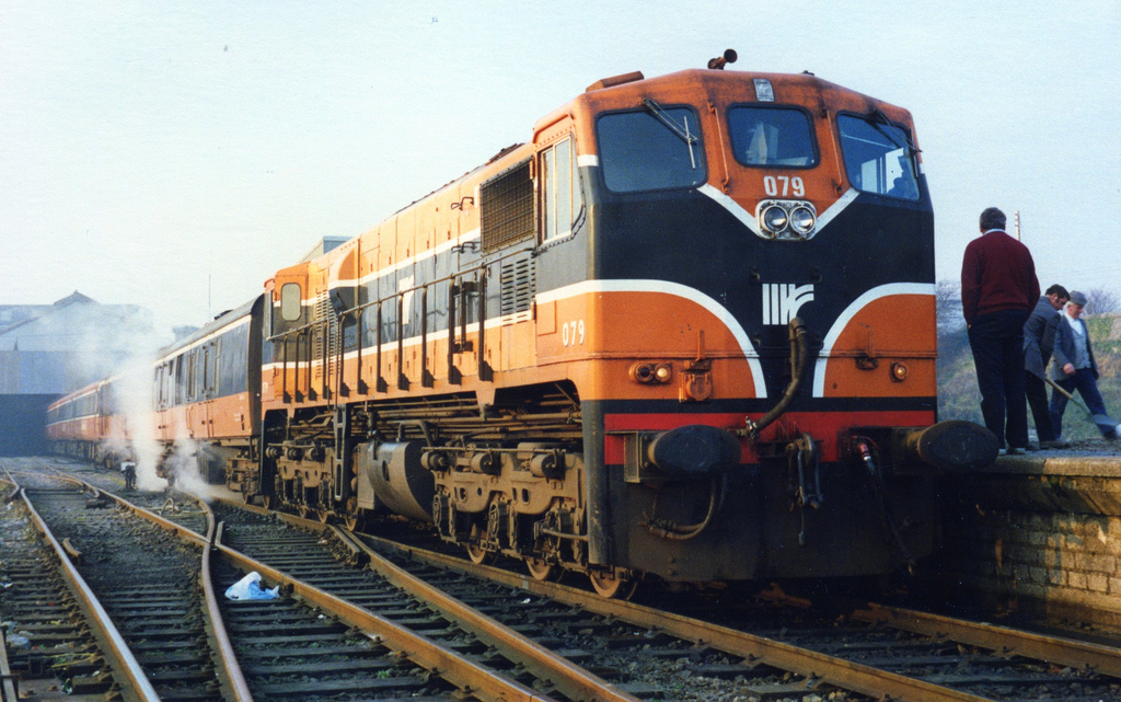
IN my quest for suitable louvres for the BSGV, I hit on a neat way to make them from raw plastikard
what I did was mount a 45 degree craft cutter ( a robust one with a circular shaft from an old craft knife set ) into my proxon pillar drill and turn the cutter so its produces " kerfs" that sit at right angles . ( the drill is not rotating )
I have the advantage of then using the X-Y table and I incremented it in 0.6mm X increments , The Y increments simply draw the knife through the material
The prototype has 32 louvres in height and this method closely resembles that number
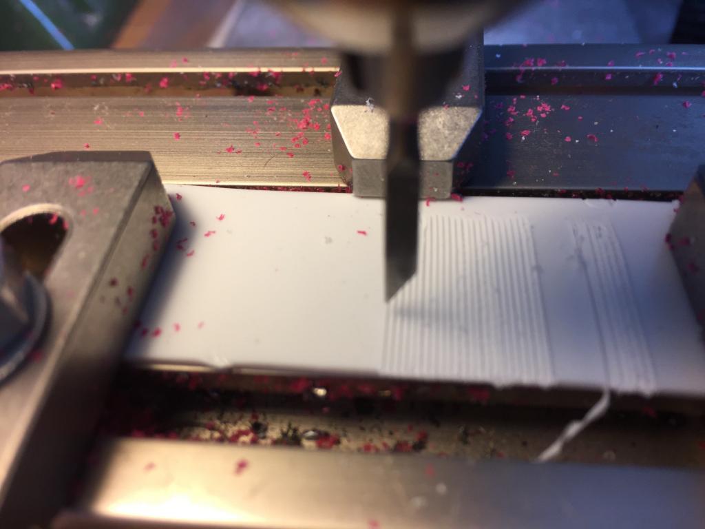
Here it is fixed into the modified Hornby Mk1 sides ( awaiting a little tidy up here and there ) Note the funny effect ¼ from the bottom seems to be a lighting effect , in real life , I cant see it
in fact the odd defect add to the realism as in practice the louvres suffered damage
all the red dust on the XV table is because I milled out the back of the windows so as to recess the glazing closer to the outside as the glazing on the old Hornby MK1 is very far back from the outside
B5 bogies from replica railways, some Keen systems LMS suspended corridors , some wire detail and better under frame detail ( diesel tanks etc ) are next on the list
-
Wow, Given my humble efforts at painting . This is light years away for me
-
thanks , I have 12mm on order
-
A question
Whats the right diameter wheel for the B5 Bogie as used on the converted BSGV
regards
Dave
-
whats the point, one hour on the train , another three to finally get to your destination in Dublin , pointless
where can I visit and photo a real bullied single sided beet wagon
in Questions & Answers
Posted
The question is in the topic title , anyone know if there are any examples that can be visted , even if in a field !
thanks