

Junctionmad
-
Posts
1,136 -
Joined
-
Last visited
-
Days Won
1
Content Type
Profiles
Forums
Resource Library
Events
Gallery
Blogs
Store
Community Map
Posts posted by Junctionmad
-
-
awesome scenes Noel , were it that CIE was ever that busy !
-
Is it me, or has design just gone, utterly gone, from any modern railway scene? Is there nothing at all with any sense of artistic merit or proportion in it?
while its no excuse, the railways were the " googles and microsofts" or their day and they had the money and a sense of grandeur. today , they are basically broke and everything is done on the cheap
-
Ps I'm modelling in the 80s , well 1980 as the centre year. Basically CIE was broke and the standard of track was awful , sumner of 80 most of Claremorris station was essentially a field of grass Everything was patch and mend and run down.
Sheesh ,now I'm depressed. Maybe I should go back 20 years
-
One only has to look at that carbuncle that is Waterford station to see the" new" Ireland design aesthetic !!
-
Jonathon , as usual yourva mine of information , thanks
-
Has this been detailed before on IRM,? I'm trying to understand the progression of CIE colours on buildings and signal cabins etc from the 60s onwards
thanks
dave
-
Trees down all over the place.
IÉ really should drill the trunks, insert a (big) panel pin and mount them into a baseboard hole. Then they would be much more stable and could easily be removed when required.
personally, they should just epoxy them down
-
I'm noticing more and more these days the attention to detail in those layouts which have a strong scenic element. Doubtless this is due to an ever greater variety of ever more realistic modelling materials,
personally I find thats good for me
plus, of course, the essential element of the layout owner's artistic talents and modelling skills.cause I seriously suck at art . !
-
nice drawing
-
Ive played with several sound chips , I have to say , I prefer the ones where most of the notching is automatic , way too much function key pressing other wise
-
want it the case that EU specifications on high(er) speed DVTs made that option untenable ?
-
I may be talking to myself here , but I find the subject very interesting
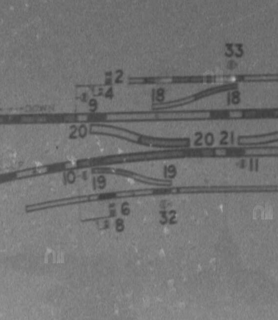
To further add to the confusion , heres Odea picture of the signalling diagram dated 1960 , three years before the one I showed in the first post ,

(© Odea Collection NLI
In my experience its very unusual to see a signalling diagram that does not reflect the reality outside the window, as they are of operational importance and are usually updated to correct any error.
Yet this diagram clearly show a typical junctional signal and it would be very hard to take from it that Numbers 8 and 4 were calling on arms . furthermore the signal priorities dont even match the photograph three years later , with the main roads being signalled into Platform 1 from Sligo but using conventional signal reading logic , signal 8 reads to platform 1 as well ( which is the conventional "up" platform " ) with the junction dolly ( 6) reading to platform 2, and none of this is the same as the photo in 1963, which is very much conventional Midland logic )
John, I also got a good explanation from signalbox.org, that midland practice after the singling of its double lines, was to prevent the operation of the home signal if the subsequent section signal could not be released ( i.e. in effect it avoided a rule 39 style of operation ) . Hence calling-on subsidiary signals were provided that read to either road. This would then suggest that the Home signal pictured above , is a main signal that equally reads to either road and a sub-sid signal under it that also read to any road. ( i.e. this was not in effect a junction signal at all )
The difference of the reality and the diagram are hard to explain ( could it be that the diagram illustrates the re-tasking of the physical signal as a loop home junction signal , even though physically it was the same signal as the original calling-on version )
-
I'm in no real hurry to ballast to be honest. I'd like to know what do I use to weather and paint my track, bearing in mind that I won't be air-brushing but painting by hand. Is there a specific paint on the market to achieve the same results as the pictures above?
you could use a sequence of conventional spray can ( rattle can ) paints to achieve the same thing, Im no artist Im afraid, maybe other hear can used the spray can method, I suspect its very hard to achieve with brush ( or very tedious at least )
-
John , heres what you said previously on the subject
............Up to the Manulla collision in the early 1960s "calling-on" arms were fitted to home signals (mother and child signal) to control movements into a station when the Main Line into the next section was blocked and the Home signal at danger. If the station was blocked the (mother) signal was held at danger and the calling on arm (child signal) only lowered when an approaching train came to a complete stop.
An AEC railcar set was blocked outside of Manulla as a C Class shunted the Night Mail. The signal man forgot to return the "calling on arm" to danger after a shut, seeing the calling-on arm in the off position the driver of the passenger ran into the loop and collided with the mail.
The rule book was re-written after the accident and the 'calling on arms" on CIE re-designated "loop homes", the home signal reading to the main-line. This was ok at stations where bracket signals were at equal height but could be confusing to a driver if the loop was on the right hand side of the running line
while I have nothing to add to this , an examination of the Manulla signal diagram , 1963 from a photo in the Odea collection , shows than the junction signal had a very specific " calling -on " subsidiary signal below it ( actually lever 1 ) the junction signal itself ( levers 2 & 4 ) being a two dolly conventional junction signal. Hence I can easily see how CIE would then remove such situation . However again this does not seem to be the situation one the Junction signals at Claremorris , the mini dollies were never calling-on arms IMHO
Interesting , There was a previous accident at Balla ( Up Mail and down passenger train ) in 1919 , where the recommendation that passing trains should not be hand signaled and that calling-on arms should be provided , perhaps this also resulted in the installation of calling on arms at other passing points
-
John , while the "The railway Archives" http://www.railwaysarchive.co.uk, contain as far as I can see almost all Irish accident reports , there is no mention of the accident you describe , anyone have the report .
-
John , many thanks
Rule 39 (a) in the old UK signalling rule book , describes the process of " checking trains" , which applies to a situation that the nest stop signal ahead of the one being approached is at danger
ie
When a stop signal is at Danger the stop signal next in rear of it and worked from the same box must not be lowered for an approaching train until it is close to such signal and has been brought quite or nearly to a stand.
This is a signalling process that railway modellers rarely understand by the way
Checking trains , was ( and is ) carried out in Ireland in semaphore areas .
This is entirely different to " calling on ".
Checking trains , can be done using any signal, and ONLY applies where the section ahead to the next signal is NOT occupied , but the signal ahead is at danger. The premise being that a driver was never presented with an unexpected stop signal. Ive seen trains being "checked" at signals regularly in the past , in this case the signal ( before the signal at danger that must not be passed ) is held in the stop position until the train draws near and is visibility slowed to a near halt ( that interpretation is up to the signalman ) that the signal is lowered and the train proceeds with the knowledge that the next signal is at stop. This is often used to draw trains into a station, where the platform starter is not yet released , for example . If the section ahead to the next signal was " blocked or occupied, "checking" was NOT used as a method of indicating " calling on ". ( where a calling on signal was not provided, in this case train would be halted at the stop signal and the driver manually informed to proceed with caution )
Calling-on is an entirely different situation , and ONLY applies where the section ahead to the next signal is " blocked " i.e., there is a train or part of a train standing in that section . A subsidiary signal ( i.e. referring to the same road as the main signal above it ) is provided, specifically informing the driver that the section ahead is occupied and to proceed with caution.
Whats perplexing in Claremorris, before the Burma road was " de-signaled " , is that the two home junction signals, one of which is pictured above , are clearly and by definition not " calling on " as they refer to a different road to the signal above. Yet in Claremorris , there is a specific calling on signal, with a yellow subsidiary arm , that is of the exact same physical construction ( until replaced by a "proper " dolly , later in the 80s)
clearly the two junction home signals cannot be calling on , yet are the same physical construction as a genuine calling-on further into the station. The mini dollies if so interpreted as junction signals are both referring to the road into platform 1 , which in Claremorris, even though closest to the station , was the loop road, and was clearly the minor road as so indicated on conventional dollies on the approach from Athlone or Athenry .
was this done because of space ?, convenience ?
A quear one to be sure
PS I can find nearly all rail accident enquiries online , even historical ones , but not the manulla one
-
I personally leave ballasting to the very end , after scenery etc. In fact I would suggest you have several months of running before ballasting. On a previous layout , I ballasted way too early in the build process and lived to regret it.
-
Weren't the roofs part tarpaulin ?
-
The cement bubble has been designed to match prototype, the one we surveyed in detail. That means it's as wide as CIE designed.
We don't compromise on scale and accuracy.
R.
With you involved , I'd expect precision=D
-
The eBay stuff is priced way over the top. You can get 071s for 130-135 euros new from the trade and 141 for 110 -eBay lunacy
-
The main question , anyone have any photos showing this mini-dolly signals ! elsewhere , thats shows the detail
There is an explanation of Mayo Road signalling in N J McAdams 2 part paper on the Mayo Line in the IRRS Journal 1976 or 77 if I remember correctly.
Briefly the mini-dollies were treated as calling-on signals up to the time of the Manulla Junction collision in 1961? then re-classified as "loop homes".
I am not sure about Claremorris but the up platform was treated as the through road at a number of stations including Ballymoe, Castlerea & Castlebar .
I have some Herbert Richard photos of the signals at Ballymore & can organise copies if you send me a PM
Thanks John.
Calling on signals in this location would never have made sense , because calling on always refers to the same road as the main signal above. ( that's the whole purpose of the signal , ie it's facilitated the interlocking to prevent the main signal to be pulled off.
These mini dolly signals seemed always to refer to the loop road. In claremorris that was platform 1 , , platform 2 was the main road. There is a genuine calling on arm in claremorris that in effect is mechanically
Very similar to the junction signals ( Which are in effect inner home signals ) it seems to be only used to signal engine run rounds on passagner trains , specially the Manulla junction empty passagner train
PM sent
-
Sorry for the very detailed question, but this is one for the signalling aficionados. Because CIE kept modifying semaphores with all sorts of bits from elsewhere , its hard to tie down specifics
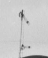
copyright odea collection, NLI
shows the junction signals on the approach to claremorris in the 1960s, note the very small " dolly " the junction signal for the minor road is more like a " calling on " rather then a junction dolly. There was two of these signals , one from the approach from Balla, the other from Kilimagh both had the dolly on the left as you approached the station
later cie replaced the remaining one ( i.e. the burma road was closed ) with a much more typical dolly ( i.e. where the lower arm was separate from the main post by 2 feet or so
in fact the both these signals are built identically to the calling on signal , further towards the station , where in that case the lower arm refers to the same track
I have detailed pictures of all the signals in claremorris, except these junction signals
Interrestinging the 1960 signalling diagram , taken by Odea, had the lower dollies on the other side of the main pole in the drawings, however several photos confirm the "mini-dolly" was to the left (which is weird as you'd expect the dollies from the Burma road and Balla road would be opposite hand
( if you see what I mean )
The main question , anyone have any photos showing this mini-dolly signals ! elsewhere , thats shows the detail
-
wow , thanks guys , loads to work on there
John Ive ordered some PECO code 65 FB , which I think will suit the repreentation of the lighter code 65 , but I agree Richie , is may me easier to just use ordinary 75 FB. we shall see
Alsi I will order the brassmasters soleplates for examination , I notice in ireland both 4 hole and 2 hole were produced. I was thinking of having an etch done for the irish soleplates as etches are quiet cheap to get made
IN claremorris , only the ballinrobe branch and the associated sidings were until last year laid in FB , ( and one siding to the other side of the main line ) . The majority of the station was laid in BH , presumably when the citation was remodelled with the addition of the third platform etc . SO for my era ( Supertrain ) BH in the station is spot on. But I will have a bash at the Ballinrobe in either soleplates or spiked
What happened to islands bridge 21mm P4 project ? , great to her someone following in Tony Mills footsteps
PS : thanks Richie for the link to the 21mm stuff, a great read
Ive just finished the crossover , so Ill have to replicate IslandBridges test in 00-SF
-
richie heres a high res photo that gives the relative views of BH and FB. ( though I cant be sure this isnt relatively recent FB track ( this should handle a lot of zoom)
[ATTACH=CONFIG]26855[/ATTACH][
Suppliers of MEK /Butanone
in Questions & Answers
Posted
anyone know if there are suppliers in ireland that can supply 1 litre bottles of MEK/Butanone , its widely used as a solvent and available in the UK from various chemical suppliers , but transport costs are a
problem
thanks