islandbridgejct
-
Posts
212 -
Joined
-
Last visited
Content Type
Profiles
Forums
Events
Gallery
Blogs
Everything posted by islandbridgejct
-
Och, the poor wee engine. Do they nay maintain the wee beastie? Superb weathering. Alan
-
I love the colouring of the Irish countryside - a real, wet summer's day. It's not exactly a major station but I remember getting out of a mk 2d set at Castlebar before the platforms were extended. Coaches 1, 2 and 3, the station; coaches 4 to 7, the airport. The guard announced that we had to move forward, but I still got off onto the ballast. I think Westport was similar. I used to use Galway station every week in the late 90s and I think that overhang is spot on. It would count as a SPAD anywhere else. Alan
-
John, Thanks for the reply. Sorry about the curveballs. That's what comes from having guru status (or was that someone else?). I'm afraid I asked the wrong question. I was forgetting that flat bottom rail gets a rebate, rather than a joggle, if it gets anything at all. I had seen the Brassmasters fb baseplates and was glad I wasn't trying to model the 70s or 80s. After seeing Rich's trouble with concrete sleepers, I think I'm glad I'm not trying anything more up to date either. I had thought the Irish North West had been relaid with bullhead at some time before closure. I must go back and look at some more pics to see what Great Northern flatbottom was like. Two bolts being sufficient makes sense, and explains why the GWR used 2 bolt chairs. It makes the 3 and 4 bolt patterns look like over-engineering. I do think I remember most of the holes being bolted on running lines. The most remarkable track I've seen is modern flat bottom on wooden sleepers held with pandrol clips. It seems like far too complex an arrangement. I'll take your advice about tinning and see how I get on. Rich, Those are great trackwork photos and thanks for the permission. The bullhead on concrete sleepers seems like a classic. How did they attach the chairs to the sleepers? Alan
-
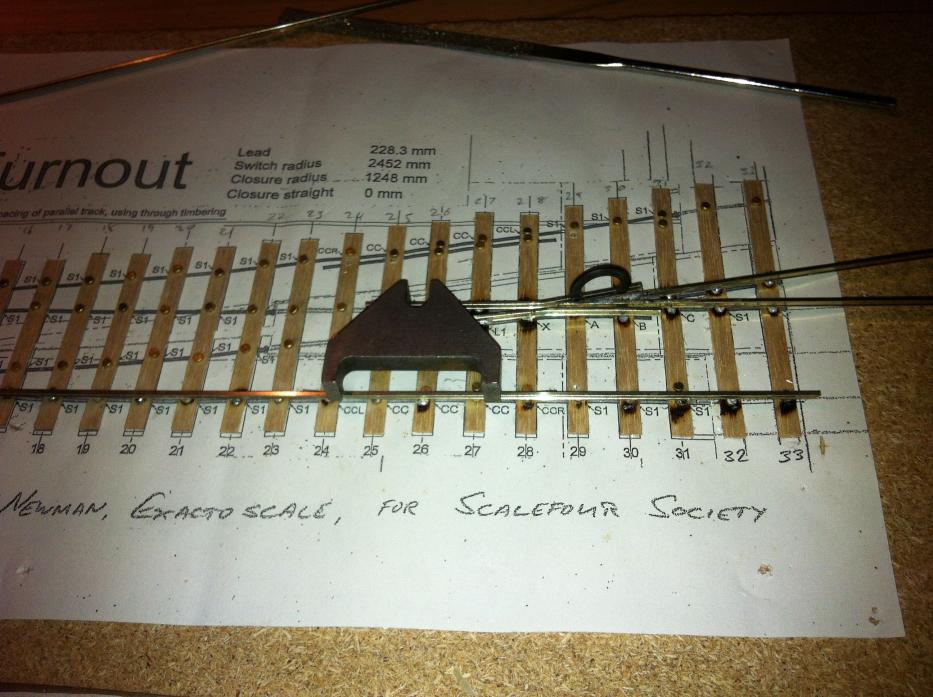
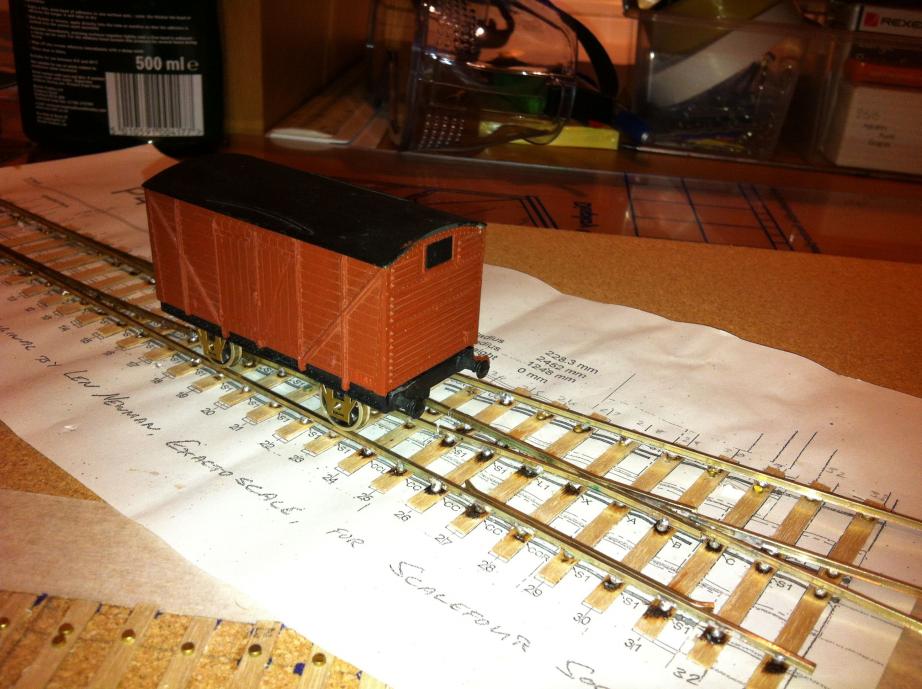
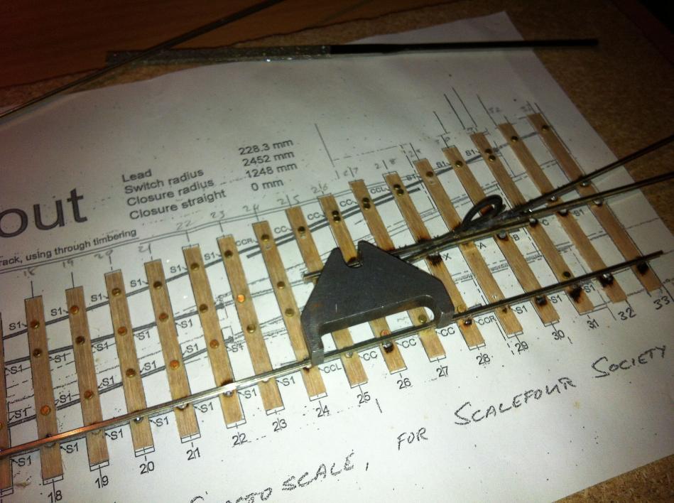
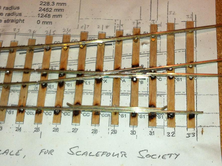
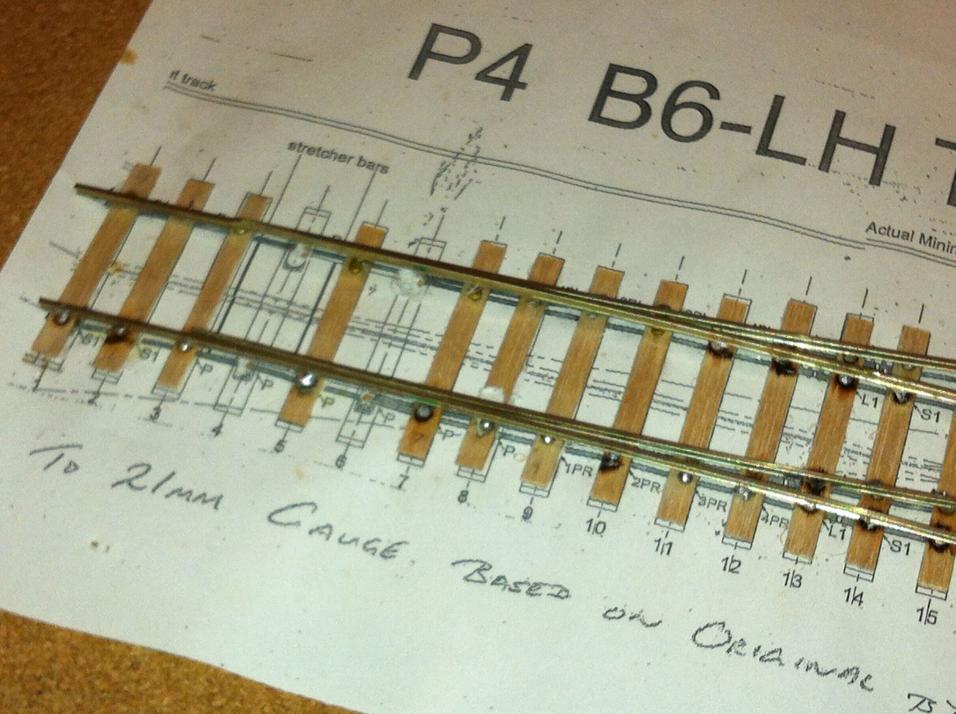
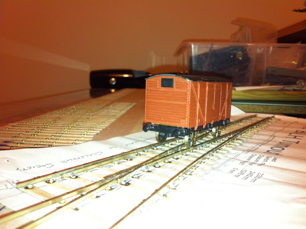
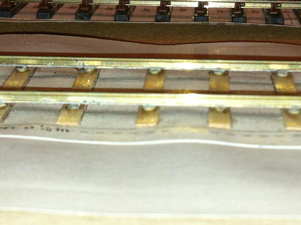
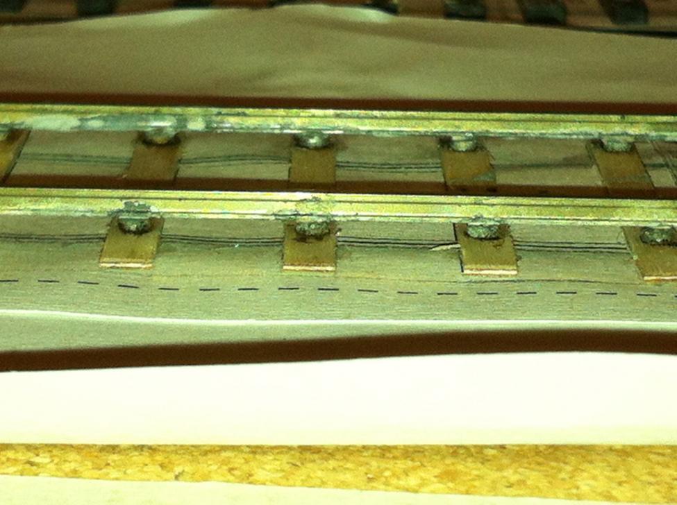
Then the switch rails / point blades. The template shows where the blade begins to taper. Use a permanent marker to mark this on the rail itself. Clamp one end of a piece of rail onto a piece of chipboard. File the other end of the rail to remove the web gradually and get a flat edge at the end. Turn it over. Bend it flat. You now have a straight rail with the web removed. This is the inside face of the switch rail. The wheel flanges will run against it. Clamp again and file the other side. File right down to an acute wedge shape. This is the outer side of the blade. Lift it up. Check against the template. Clamp again. Keep going until it's right. File off the top point of the wedge – don't want the wheels hitting the toe of the turnout.When it's finished, cut the far end to the correct length. (Or use a cutting disk, cut it a bit long, and file it down to the correct length.) For the curved switch rail, repeat the process. Then bend the rail to shape. Then cut. Attaching the track. Solder the common crossing (vee) in place, relying on the template. That is, clean, flux and solder it. Next solder the straight stock rail. (That's the outer rail on the straight road.) Use the track gauge to get it the right distance from the point rail. I put a joggle in the straight rail where the blades are housed. (As John points out above, you don't do this for flat bottom track. Use a rebate instead – ie, file a bit of the rail away to provide a housing for the blades to lie in out of the way where they won't get hit by passing wheels.) Some companies joggled their turnouts and some didn't. I haven't found out yet what the GSWR did. I didn't think to put a set in the curved stock rail until too late. One for next time. Now the straight wing rail. Gauge it off the straight stock rail. Use a flangeway gauge to ensure adequate flangeway. Use a steel rule to ensure it follows through in line from the point rail, otherwise wheels running through will hit the nose of the common crossing and derail. img 210 img 211 Notice that I did the diverging wing rail first. Bad idea. There's nothing to gauge it against until the diverging stock rail goes in. Solder the diverging stock rail in place. Just do it lightly for now. 4 or 5 joins will be enough. Check the gauge at each end. The gauge in the middle will be gauged along with the switch rail, so the middle is not fixed at this stage. There's a bit of a gap in the photo record at this stage. I'll get some better pics on the next one. It was about this time that I realised I'd left out some of the holes for the check rails. The options were to go back and restart, or push on as far as I could and see how things work. I decided to push on. This is only a test run, after all. I decided to make the closure rails and switch rails in one piece, so the next thing to do was to lay the straight one, gauged off the straight stock rail. Repeat for the curved line. Put roughly in place first. Then finish soldering the diverging stock rail. Then finish soldering the diverging closure / switch rail. Next the check rail. Out with the P4 Roger Saunders gauge to make sure there's wheel clearance through the crossing and check rails. Adjust the wing rails to make sure everything lines up. The great thing with solder is, if the joint has worked, you can melt it and realign it a little to get it right. The end result is something like this. It's missing one wing rail, missing any point actuation device, and missing any wiring or electrical switches, but it's basically a set of points (almost). img237 Comments? 1, Try not to burn the sleepers when soldering: it's not railwaylike. 2, Make sure you've got all the rails you need, all the holes you need, all the sleepers you need, and everything else: make a checklist. 3, Don't attach the switch rails so close to the end: they need more room to flex. Bear that in mind when soldering everything, and make sure to gauge the stock rail off the switch rail for the flexi bit. 4, Why is the wing rail sitting lower than the running rail. Ah, it's because of the tinning. Take John's advice and don't tin. Just make sure to flux well. img350 - img353 Verdict I ran a vernier calipers over the whole thing and it's in gauge. At least, as much of it as I've completed is within P4 tolerances. Calls for a minor celebration. Grab a Lima box van with P4 wheels and run it through. Over. Back. Over. Back. OK, now you're just playing trains. img348, img349 Stage 2 will be 1.2m, double track, bullhead, with B6 crossover, ballasted, laid on cork. It's under way at the moment and I'll post it in due course. Alan

-
John, could I ask you a question about flat bottom track. As I understood it, mainly judging from photos and what I observed from the 80s onwards, the practice of laying flat bottom track on chairs began in the 60s when CIE moved from bullhead to flat bottom rail. When the Midland laid track, it was all flat bottom and it fixed it straight to the sleepers, American style, or possibly used a small clip but no chair. Is that right? Sidings everywhere seem to have been laid with lighter flat bottom rail spiked directly to the sleepers. I'm also wondering about the pointwork. There's no sign of either a set or a joggle in that turnout. Have you any idea what the Irish railways' practice was on the subject? (For anyone else reading this, a “set” is a kink in the diverging rail of a turnout, at an angle of about 20 degrees. The switch rail sits against the set, so that the end of the blade does not stick out into the 5 foot where it would get hit by the wheels of stock running straight through the turnout. A joggle is a kink in the rail to achieve the same result. Some of the stuff you read on the subject can be contradictory or incomplete, but this is worth a look: http://www.templot.com/martweb/gs_realtrack.htm#joggle Rich, I like the pictures of Clonmel, particularly Irish Rail's approach to bolting down chairs. (Sure what would we do that for?) Would both of you mind if I downloaded your track photos? I've very little on the subject myself. Also, would you have any pictures of the through timbering on a crossover between two running lines? John, I note your practice of just letting the solder flow into a well fluxed joint using capillary action. I may give that a try. I was just following old metalwork rules which say, flux, tin and sweat together. (Tinning, for anyone reading this and scratching their heads, is putting a small bit of solder onto the 2 surfaces to be joined, and sweating is heating the metal until the solder that's already been applied melts.) 3 things to note about bullhead rail, for anyone interested. 1, the chunkier part goes at the top, because this is the part that gets worn down by the wheels - so the rail always looks like it's upside down. 2, the metal clips in Rich's picture are probably post 1960, before that wooden 'keys' were used to hold the rail in place. C&L and P4 Track Co chairs have wooden keys. 3, the GNR used 3 bolt chairs, while the GSWR / GSR / CIE used a 4 bolt pattern (though I suspect used panels from both could be relaid anywhere on the system after 1958 – I think I've seen photos of the sidings at Limerick Junction laid with GNR bullhead panels, and possibly of Drogheda-Navan with GSR panels.) Alan
-
irish P4,21mm, advice on loco conversion, track gauges
islandbridgejct replied to pewky's question in Questions & Answers
Hi Luc, I'm probably about 6 months ahead of you on the trackwork side of P4. I've just started posting it on the workbench, under "gswr 101" if you're interested. It might save you from some of the learning curve I'm on. (On the other hand, probably not - nothing I read prepared me.) Alan -
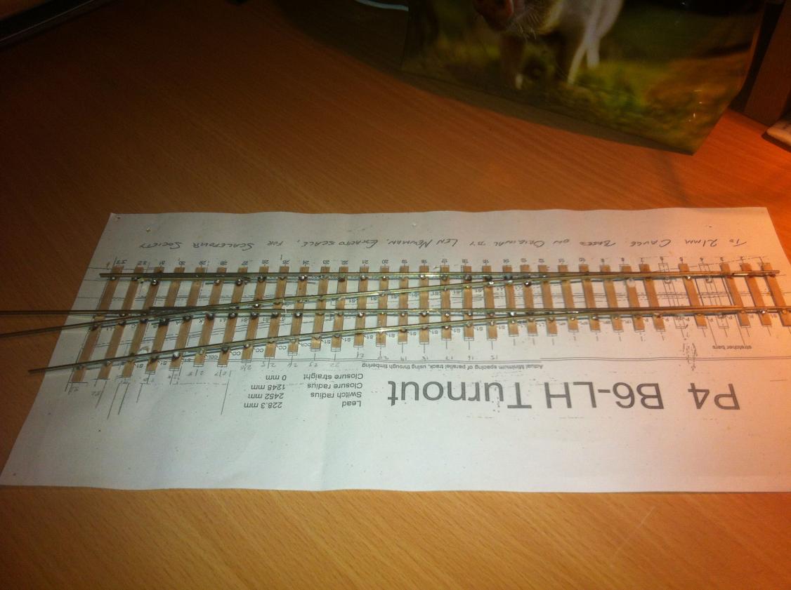
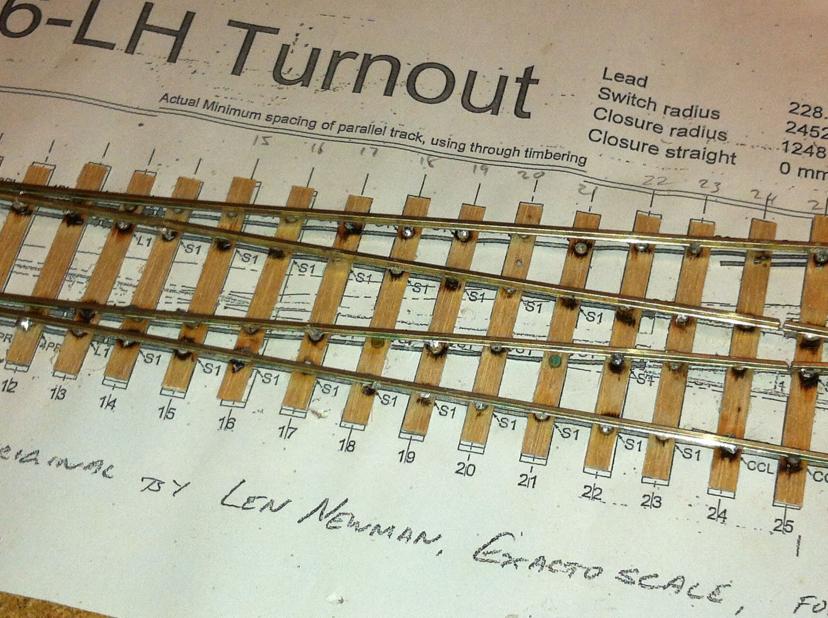
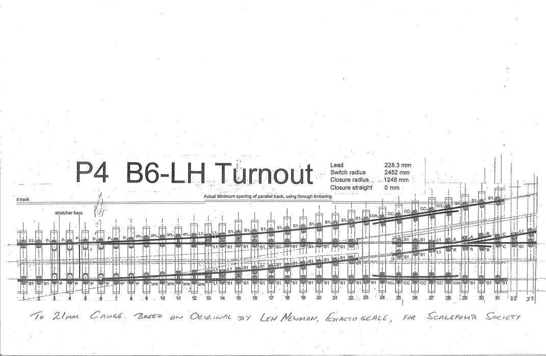
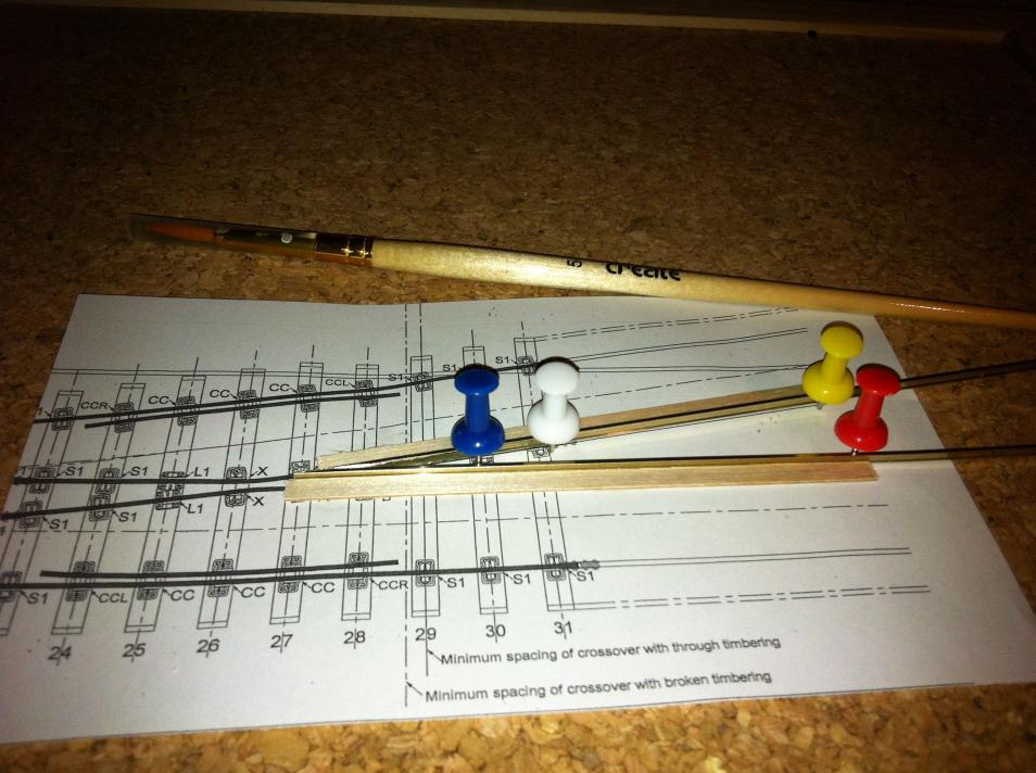
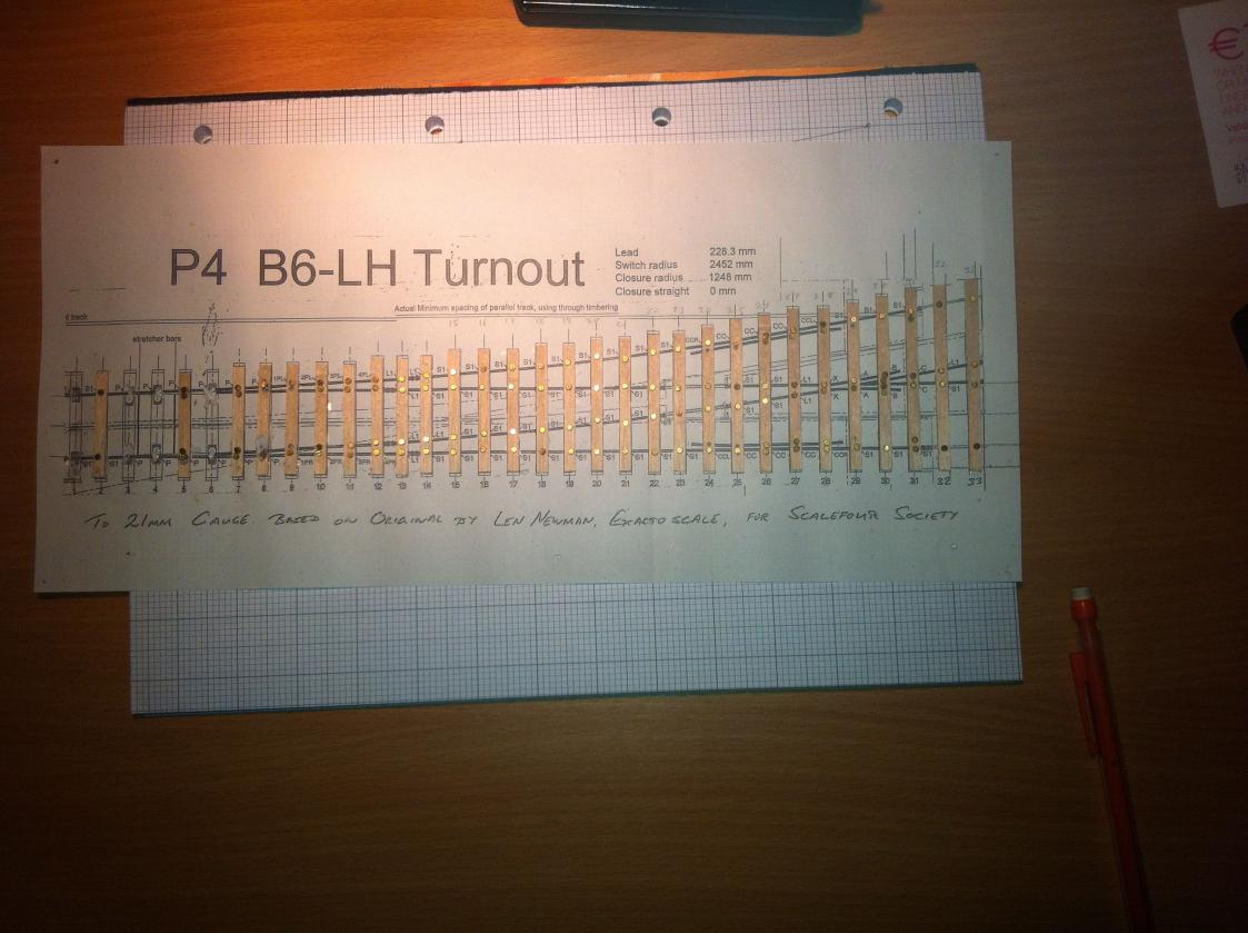
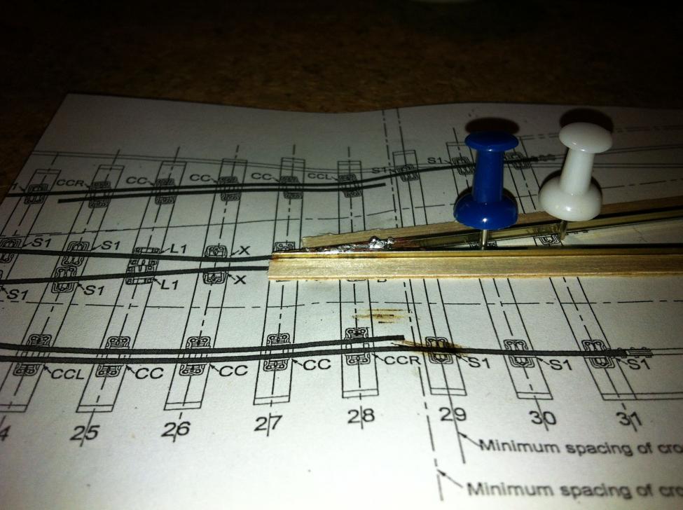
One more instalment before the weekend. * OK, points. Templates The first problem with turnouts is templates. The easy way to resolve this is to get a copy of Templot. It can generate turnout printouts in 21mm gauge, and away you go. However, I didn't know what a P4 turnout looked like, or what size it would be, and wanted to make one or two before I invested in Templot. (Also, my MacBooks keyboard doesn't work, which means I use a USB keyboard, which prevents me installing anything that disables the USB port, which prevents me installing Boot Camp, which prevents me installing Windows, which means I can't use Templot at home. I'll have to set it up on a work computer instead.) So I got the templates from the Scalefour Society Stores and wondered how to convert them to 21 mm gauge. Ultimately, it's fairly straightforward, but hard to describe. Cut it in 3. 1 part is the crossing. 1 part is the straight side. 1 part is the diverging side. The cuts are made along the centre line as far as the joint between the wing rails and closure rails. You need to draw the centre line first. Where the closure rails come together, you need to keep the cut about mid-way between the two rails. Now the 3 parts have to be stuck back together, but slightly further apart. Get a blank sheet of paper. Mark out a straight track and centre line, 21mm gauge, so 10.5 mm between each line. Glue the straight side template piece down, in line with one rail on the lower sheet. Place the diverging line piece loosely on the lower sheet. Place the crossing piece so that it aligns with the appropriate rail on the lower sheet. Now slide it out until the wing rails align with the closure rails. Glue it down. Mark a 21mm gauge mark for the diverging line, measuring from the splice rail on the crossing section. Now make sure both ends of the diverging track section and the closure rail on that section all line up with the rails they connect to. Draw in the missing sleepers. I was lucky: a B6 turnout works with exactly 2 extra sleepers in it. The check rails end up out of position and have to be moved. You can do this now or do like I did and wait until you're half way through building your first turnout to find out. Anyway, there it is: one template. b6 Note the cut between sleepers 22 and 23. Sleepers 23 and up in the crossing unit have been moved outwards so that they line up with sleepers 25 and up in the outer units. I've filled in the missing sleepers and tracks in the gap near the crossing, and I've extended the outer units for a further 2 sleepers. This is all a bit rough and ready, but it seems to work. (If anyone wants to tell me why it's wrong, that'd be great.) Notice that the check rails got left behind, causing problems later. If this sounds like too much work, it is. It took me about 2 weeks to figure out what to do, and the result is only OK. Next time: just get Templot. Alternatively, Exactoscale said I should contact Len who might be able to sort me out. Points about points. Before I go on to the actual building, I'd point out that a B6 turnout is 320mm long. That's a lot bigger than a large radius Peco turnout; and B6 is really the minimum for main line use. A “C” or “D” turnout will be even longer. This is the real issue with size in P4 or EM – the turnouts are huge, which means you get a lot less layout into the same space. You may compromise by running short trains: 4 six wheelers or an equivalent length of wagons, or a nice little mixed train. And that's before you start to think about the curves. Minimum radius is over 3 feet for six coupled engines, and you really need more if you can manage it. Overall, even with discussion of small prototypes, finescale track needs length. But it looks superb so it's worth it. To be more accurate. I think it's worth it; but I can well see why someone else wouldn't. Building turnouts It took several weeks screwing up my courage before I could move on to building the things. When I did, it wasn't nearly as bad as expected. Difficulties are: the common crossing (“vee” or “frog”), the point blades, the wing rails, and the check rails, in that order. First lay the sleepers. Cut to the correct length. Drill holes for the rivets, 1.2 mm diameter. I had to order drill bits from Eileen's Emporium for this. I got shanked ones. These don't fit into their Archimedian hand drill. (Don't ask me what Archimedes had to do with drills: I don't know.) Shanked bits are ones where the bit that goes into the chuck is wider than the bit that makes the hole. I then got an electric drill. It's difficult to get the hole where you want with the high speed rotation and the holes marked with pencil (see Iain Rice's Approach to Finescale Track in 4mm). I resorted to using my trusty pointy tool to make a dent in the sleeper. (I think it's a scriber. In retrospect, I should use an awl.) Latterly, I just use the drill bit in my hand, but it still slides as I drill. I think it's because of the grain in the wood. (And not just because I can't do accurate.) img091 img092 Sleeper timbers are 12” wide. Normal timbers are 10”. The Scalefour Stores sell both. Amazingly, you can actually see the difference. img193 Next the crossing. This is the hard bit. File it like they say in the P4 Digest. Then assemble. I built a temporary jig as shown: 2 bits of sleeper timbering set at 1:6, glued to a part of a template. Pins to hold the rail up against the wood. A cork board underneath to hold the pins. File and check. File and check. When the 2 rails fit together right, flux and solder. img0197 Next time: do it upside down. That way there won't be so much solder on the top of the rails needing to be filed off. img0199 Obviously, there's more to come, but it takes a while to write it down. More next week, hopefully. Alan
-
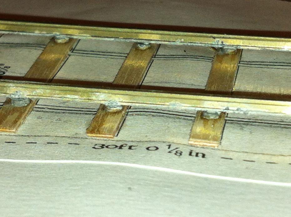
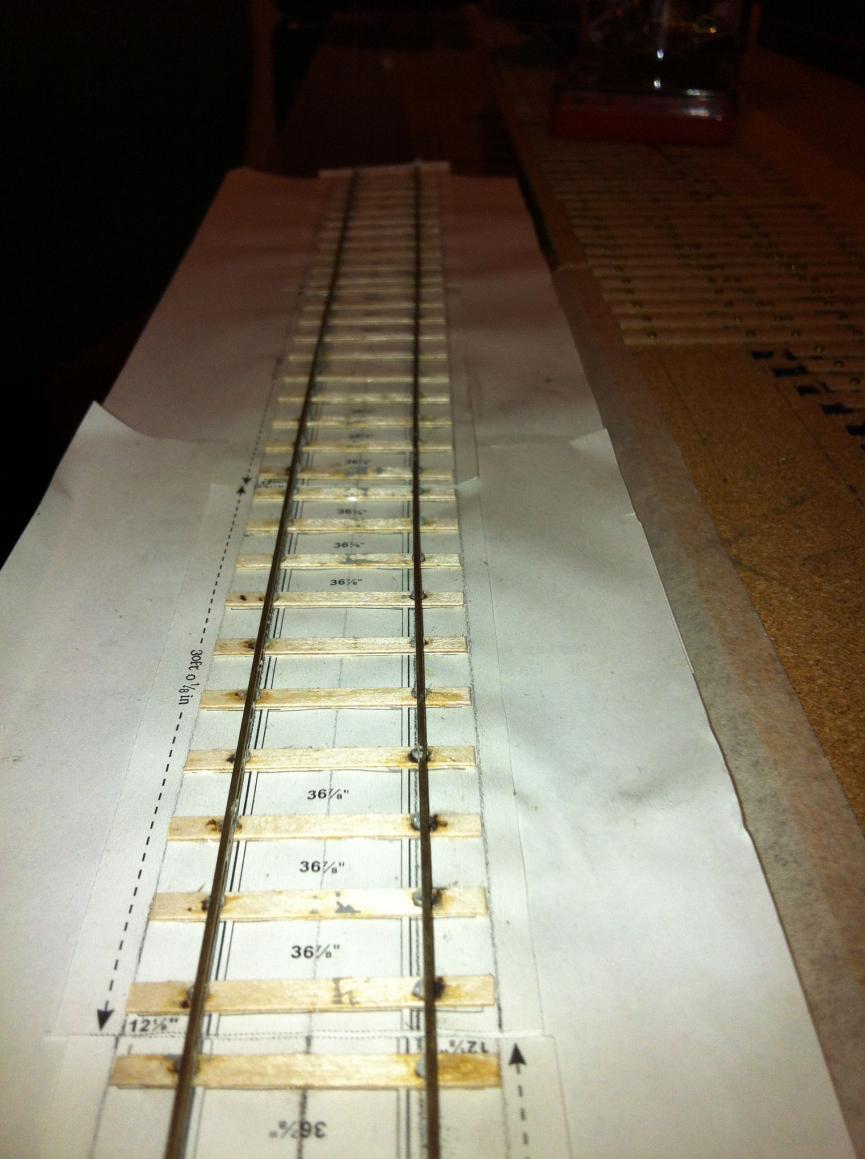
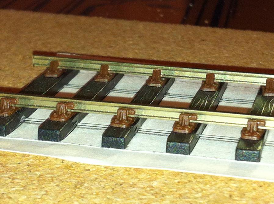
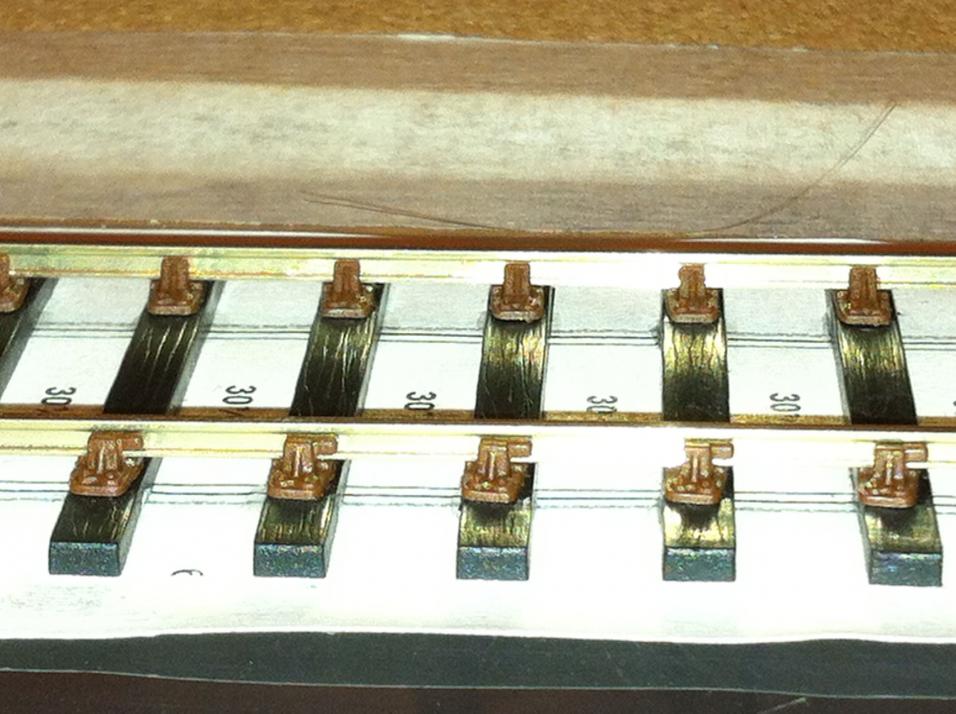
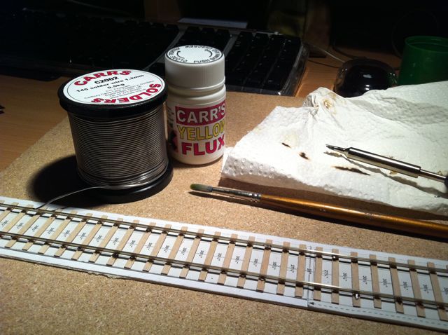
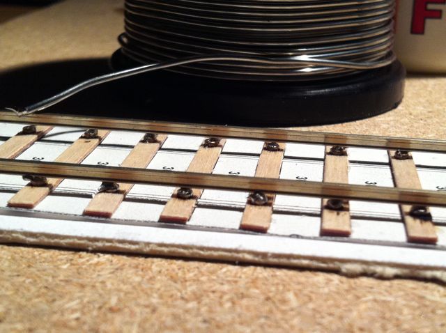
I took some extra photos last night, so a bit more about straight track before I move on to points. img368 The eventual solution to poor fluxing and too much solder was to move to solder paint. This is small grains of solder suspended in flux. The procedure goes like this: Sand the rivets. Sand the bottom of the rail. Use an alcohol cleaner on both. Allow to dry. Paint the solder onto the rail and rivets with a brush. (Hold the rail with a clothes peg sized clamp at either end, to keep it upside down while you do this.) Turn the rail the right way up. Try to get it sitting on the rivets before the solder goes everywhere. Heat the iron. Apply the iron to the side of the rail at the first joint, until the solder melts. (It turns from dark grey to silver.) Take the iron away. Push the rail up against a steel straight edge to make sure there are no kinks. (Kinks: good in a 60s band; not so good on a railway.) Solder the joint at the far end of the straight edge. Solder the joint in the middle. Use a pointy tool to press the rail down as you solder. Hold the tool there until the iron has been removed and the joint is solid. The rail should now be straight. Solder all the other sleepers. You now have one rock solid rail. Start the other side. Prepare the rail and rivets the same way. Stick a track gauge either side of the first join. Solder the first join. Roll the track gauge along, about 10-15 cm. You'll come back to the sleepers in between. Track gauge either side of the joint you want to make. Solder it. Repeat until you get to the end. Second rail is now fairly gauged off the first. Go back and solder all the joints you left out. Keep using the track gauges as you go. Run a roller gauge along the full track. Does it stick anywhere? Heat a few joints and try to loosen it out. Roll a set of wheels down it. Oops. Where are they? Is that flux on the carpet? Emergency clean-up. (Don't forget to bang your head when getting out from under the desk.) Tell nobody. The result should be a nice series of neat well-soldered joints. I should have cleaned the flux off when I finished. Must develop a procedure for that: don't want to soak the plywood. See how the paper has crinkled up. Iain Rice says to stretch it and stick it down, but that then it acts like a loudspeaker. I could build it on the paper and then remove the paper before laying, but that won't work for the chaired rail, where the rail is free to slide through the chairs. I've some thoughts on how to get around it, but I'll keep them for my test plank, which I'll get to in a while. img369 Quite a nice piece of track. Not too much solder around. Could do with a clean. img370 More of the same. img376 Looking along the length. This is usually where the kinks turn up. Prototype sidings can be the same. I'm quite pleased with this. 3 older 30 foot lengths with 36” spacing between the sleepers. These are three separate templates, stuck down one after another, and I didn't get things quite straight, so each length goes off at a bit of an angle. Should have used Templot! (And I will, Rich, now that I'm started.) Old trackwork really looks quite different, with the wide gaps between the sleepers, but as far as I can figure out from pictures I've seen and an old section of track in the bay at Ballybrophy, the sleeper spacing on the GSWR by 1910 may have been closer to modern standards. Does anyone have any pictures of GSWR track? I'm working off this advice from John on the yuku site last July: “I would not get too bogged down between rail cross sections, the visual difference between the*lighter rail sections is fairly marginal perhaps 1/2" or .15mm in rail height and foot width between 80 and 95lb rail.** The increase in rail weight and move to bullhead on some lines was driven by the increase in axleload and faster speed in the early 20th Century, also improved quality of steel meant that rails lasted a lot longer. 80lb rail cascaded out of the main line in the early 1900s might last for many years in branch line use, 90lb rail laid down by the MGWR in the 1920s lasted in service on the Westport and Sligo Lines until the 1990s, some GSWR bullhead from the early 1900 may survive in service to this day between Waterford and Bellview and onwards to Rosslare Strand. The*MGWR*main line system* had been upgraded to*85-90lb rail and bridges strengthened*to*allow**its large relatively modern*4-4-0 & 0-6-0 Classes to work through on all its principal routes. While the Meath Road to Kingscourt and Athboy looked fairly*run down*in CIE days the tri-weekly North Wall Kingscourt Goods was regulary worked by a large MGWR or GSWR 0-6-0s. In contrast the ex WLWR the lines North and West of Limerick were restricted to*small 0-6-0 and 4-4-0 types*frequently requiring overload goods and double heading of excursion traffic.* The introduction of the Metrovicks and Bo Bo alleviated*the route restriction and axle load*problem, but the 071s aand 201s were too heavy for the surviving 90lb rails leading to track damage and the need for wholesale relaying in the 1990s.” I haven't been able to get to the Waterford – Rosslare line, or even as far as the IRRS and that's less than a kilometre from the office, so any pictures anyone might have of old trackwork, showing the sleepers, would be useful. img372 This is the C&L system, with functioning chairs, fixed to plastic sleepers with solvent. It's much easier to build than the ply and rivet. It looks better. And it lets the rail slide through the chairs, so it'll probably give a better ride quality. But the painting will be harder. Also, you can't lay the sleepers, then ballast, then put in the track, so it's going to be a bit more awkward to use. P4 Track Company / Exactoscale do a similar product with plywood sleepers. Rich mentioned it above. That's what I'll use ultimately. But the ply and rivet is good practice for the moment, and the stronger system may be better for points. I can always use the chairs in a cosmetic way. img373 The little wooden keys go on the outer faces of the rail, on the side of the chair the train is coming from for a double line, so the vibration from trains passing over doesn't work them loose. (For single track, pick a side: one training shaking the keys loose should be balanced by another working them back in. Employ a good ganger.) Make sure to get them all the same way. Cut them off the sprue. Separate into two groups. Thread onto the rail. Push into position. Then put the solvent on at the ends first. Use the straight edge to make sure the rail stays straight. But I never heard of a prototype issue with chair creep. Note the chair wandering off the end of its sleeper. This happens when pushing the rail down to ensure a good join. One to watch out for. img374 Looking along the tracks. That's all for now. Alan
-
Rich, Jim Smith Wright's Birmingham New Street has to be the last word in modelling. He's the Albrecht Durer of model railways. He even modelled the phone directories in the phone box. I'm hoping to do something a little less detailed. Have you seen his video of HST tests on the storage roads for Calcutta Sidings? They're quite phenomenal. Fran, thanks for the link. That collection of layouts is going to repay some detailed study. John, sorry to hear about the problems with your track clearances. It looks like a great layout. You should really relay it: it deserves to be up and running. I'll come back to that point about operation of short trains – it's on my mind a lot as I think about layout ideas. Alan
-
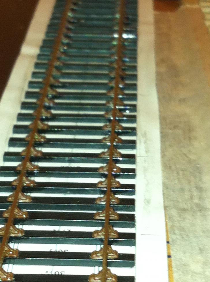
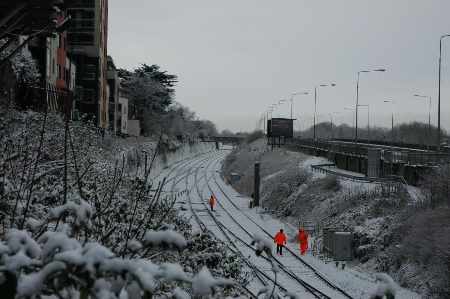
Thanks for the encouraging words and the warm welcome, and keep the advice coming. Rich, I'm planning on moving on to the P4 track company's sleepers for the reasons you mention – plywood sleepers and accurate chairs for all the pointwork being the main ones. I decided to stick with ply and rivet for the moment though, because I want to be improve my soldering before I tackle any brass kits. I've a particular way I want to do the painting, which is why I didn't stain them in advance, though I read your piece on staining and Iain Rice's passage on the subject in An Approach to Finescale Trackwork before I started. I'm also planning on using Templot, but I need to get 'Bootcamp' up and running on my Mac first. I'm trying not to get a whole load of stuff before I'm ready to use it (but the temptation is immense.) I take your and John's point about the gorgeous little stations on the network, though when I started looking at them, most would scale out over 3m. The shortest ones seemed to be on the Burma Road, but train service was a bit basic. I'm wondering about letting the GSWR take over the Bandon a few years early, and running a J15 onto Baltimore or Bantry quay. The idea of a quayside layout really attracts me: one of the best pieces of railway writing I ever read was Iain Rice's “Tregarrick Regained” in the 1980 or 81 Model Railways. I'd no idea, John, that some of his plans originated in Westport Quay. I looked at it, but the problem was that the line didn't run down onto the quay at all, so I couldn't put the trains and water together without changing things around. Newport's a lovely station, with a viaduct straight out of a tunnel and straight into a station. How often do you find that in reality? But the service pattern is quite light. I think if I wanted a layout with mountains and sea, I'd go for the Valentia branch. Anyway, that's all for the future, I have to try to keep focused on improving my skills for the moment. Anthony, I'm a big fan of your Irish Rail stock, and with your videos on the site, I even get to be the one sitting and watching it go by. Fantastic stuff. I think the ultimate tail-chasing 00 layout at the moment has to be Peterborough North on RMweb – I wasted a whole load of time reading that thread. John, I'm taking your point about the small test track. That's where the 1.2m of double track with crossover that I'm working on at the moment comes in. I plan to build a second one the same length, and figure out baseboard joints, and use them as a shunting plank and a test bed for some scenic work. I love your little Liffey branch. I've been looking at Paul Greene's Killorglin on the S scale society website. It's the only clue I have to what the GSWR's green loco livery and its purple lake carriage livery were like. Am I right in thinking that no. 36 in Kent Station is in CIE lined green rather than its original livery? Or that 186 and 184 were painted in GSWR colours during the shooting of The First Great Train Robbery? Richie, thanks for the encouragement. I've just been looking at your buildings thread. That's a superb standard of work. I might ask you some questions about it when I get that far. To progress things, here's a picture of what I'm trying to replicate in terms of the look of proper Irish trackwork. It's taken from the South Circular bridge, looking towards Inchicore. The snow really makes the similarity between the 5ft and the 6ft stand out. The other thing that I really notice between the real thing and most models is how narrow the flangeway in the common crossing is. (That was what did for my bubble wagon.) I'll move on to points next. Alan
-
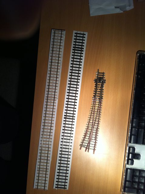
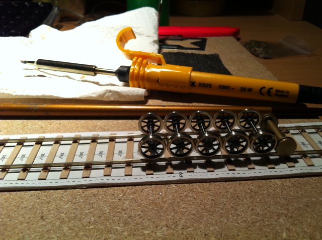
Now to see if I can add some pictures. Img 0056 These are my first two pieces of 21mm track, alongside the Peco point that caused the problem in the first place. The difference in gauge is readily apparent when the two tracks are side by side, without ballast. One rail is ply and rivet construction, the other is C&L plastic sleepers and chairs. The C&L looks much more realistic with the chairs holding the bullhead rail, and is much easier to build, but I'm sticking with ply and rivet for practice for now: it's cheaper; it'll improve my soldering; and I'm only building stuff I won't use in a layout for now, until I know what I'm doing. I was surprised how little bullhead rail there was in Ireland before the late 30s – really just the GSWR main line and the GNR. The Midland used heavy section flat-bottom, and sidings were almost invariably light flat-bottom rail. The DSER wasn't relaid until the late 30s or so, judging from pictures. Img 0052 I laid the rails directly onto a Scalefour Society template. The GSWR laid the Rosslare – Waterford line with 45ft sections in 1906, so I'm taking it that 45ft lengths are about right. Mind you, I can't decide which English company's template to use, and they have quite different sleeper separation for the same length. I also don't know yet if they used 45 ft lengths on the Cork line which could have been relaid earlier, so I've some more research to do. Img 0053 Rails and wheels and rolling track gauge. Put the P4 wheels on the track. Tilt the track. Run them up and down. They don't fall off, so at least I got the gauge more or less right. (I think this is the finescale equivalent of playing trains.) Img 0054 Some problems with soldering. Going back to my old metalwork teacher's instructions, first you clean the joint, then you flux the joint, then you apply solder to both sides, then you sweat the pieces together until the solder melts. Problems I encountered were: not cleaning the joint properly and not using enough flux, so that the joint fails; and putting on too big a blob of solder, so that the rail does not sit down properly and letting the solder harden without pushing the track down into it, thereby leaving the rail too high to make the next joint. Result – with a loose sub-base you get level track but unlevel sleepers. The moment you try to put it down on a flat surface, all the inconsistencies become apparent, and the poorly fluxed or cleaned joints start to fail. Just as well this rail was just a trial. About half the joints have failed. (Hmmm. Better luck next time. Better prep next time.)
-
My bubbles always used to fall off the track. In fact there was only one bubble wagon, an MIR one, and it only fell off at the common crossing of a Peco large radius curved point at the entrance to my station. At the time, all I knew about finescale standards was that some Peco points were called finescale and some were called universal. I didn't know you couldn't run finescale wheels through universal crossings. I had read loads of back issues of Railway Modeller, and was aiming for a realistic, modern image, CIE layout, but every time that little bubble wagon hit the crossing, it derailed. I was stumped. Before I could resolve the problem, college and life intevened, the railway got put into the attic, and here I am, 25 years on, finally getting back to some modelling. The problem, it turned out, was incompatible wheel and track standards. The bubble wagon had Alan Gibson's finescale 00 wheels, which have narrow flanges and tyres, while the track was coarse scale to allow the steamroller tyres and flanges of old Triang equipment to pass through. To solve the problem, and make sure I didn't have it again, I had to settle on one set of track and wheel standards. At the same time, I was unhappy with 00 as a scale-gauge combination. It's not so much the track itself, although at 4.5 mm under-scale, it's closer to the Tralee and Dingle than the Tralee to Dublin. It's more because the 6 foot way between the tracks has to be increased to compensate, so that instead of having two tracks and a six-foot of 21:24:21 mm, you end up with 16.5:30.5:16.5 mm. That leaves the gap between the tracks almost twice as big as the gauge, rather than being nearly the same size, and it was something that bothered me. The choice then was whether to go for 21mm gauge and 4mm scale, or try some other combination. I thought about 1:100 (approx 3mm scale) which would give a gauge of 16mm, for which I felt I could use 16.5mm track; but the track would then be 33% overscale, even if I used finescale 00. More significantly, so would the wheels. It seemed easier just to use 4mm scale, and rely on all the support available in terms of finescale products in that scale. I thought about 2mm finescale as well, but felt the models would be just too small for me to make accurately – and I'm short sighted enough already. Having settled on the scale and gauge, I still had to decide what set of track standards to use. 00 finescale would be fine, but seemed a bit nebulous – nobody really defines what the standard is. EM and P4 both had well set out standards, but P4 track (if done well) looks that little bit better. The one thing I didn't want was to start off in one and then decide I wasn't happy with it and scrap everything to go for higher standards, so it seemed better to start hard and, if I can't master it, drop back to something a bit more forgiving. (A bit like learning to run first and then, if that doesn't work, consider walking. Don't ask – it made sense to me at the time.) In the meantime, I had seen Adavoyle at the SDMRC show, and had spoken to Tony Miles, and that really sealed my choice. So I finally made a start last September (having sworn I wouldn't read Irish Railmway Modeller in the meantime, so as to stop me wasting time) and, at a snail's pace, I've produced four pieces of track and one set of (almost functional) points since then. I've now moved on to producing a 1.2 m section of double track with a B6 crossover. It's slow work – at this rate, Irish Rail will have the DART interconnector before I have a layout – but I'm figuring everything out from scratch as I go, even the basics of soldering and drilling holes in pointwork sleepering. I'm also getting a bit quicker as I repeat basic processes. That's where I am at present - effectively “course 101” in finescale modelling. I'm a basic grade, entry level, 21mm gauge P4 modeller (with an option on EM or 00 standards if I can't make things work at P4.) So what's this got to do with the GSWR? Well, after reviewing all the books I could find, I wanted to build a model set at a time when the railways were in an optimistic mood, with a decent level of service. I initially thought of CIE about 1950, but I preferred the look of the locos before they were rebuilt, reboilered, superheated and all, and GSR battleship grey was a bit of a turnoff too. I feel Adavoyle really 'nailed' the Great Northern, and I didn't want to just produce a pale imitation. I prefer tender engines to tank engines (that one goes back a long way – Edward, not Thomas), so the CBSCR was out. Service level on the WLWR and MGWR seemed lower than I wanted. The Midland stations were very long and very narrow, so not great for a limited space. So the GSWR about 1910 was what I decided to aim for. That will inevitably require one or more of Mr McDonnell's little 0-6-0s, hence the title for this thread. As I'm doing “course 101” on finescale historical modelling, any help and advice I can get from the members of this forum will be more than appreciated. (I'll probably put this post up on rm-web too for the same reason.) Also, my own trials and tribulations might help others who are at a similar stage, or more likely give them the chance to say, “well, I'm definitely NOT doing it THAT way.” I want to stress that I am NOT trying to restart any gauge / standards debate. (There's enough discussion about that on other threads here.) There's an awful lot to be said for just switching the controllers up to max and sitting back lineside and watching the trains roll by: it's probably what got most of us interested in model railways in the first place. Also, compromising on gauge leaves a lot more time for working on other aspect of realism, and some of the work on this site is superb. Sometimes I wonder if I'm mad to try this; but what the hell. Thanks, by the way, to Gerry Byrne for encouraging me to start (though he didn't know quite what I had in mind) and to John Mayne (whose path I must have crossed many times in George Hannon's model shop in Malahide in the 70s) whose posts on this site helped make the start a bit clearer. I'll post some pictures below of what I've been up to, and show some of the failures along the way. Alan