

Horsetan
-
Posts
2,089 -
Joined
-
Last visited
-
Days Won
4
Content Type
Profiles
Forums
Resource Library
Events
Gallery
Blogs
Store
Community Map
Posts posted by Horsetan
-
-
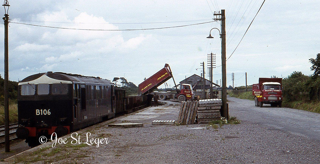
the only one that is flat is the central one, and it's angled backward. the sidelights follow the curve of the upper part of the cab above the crease.
This photo illustrates it nicely.

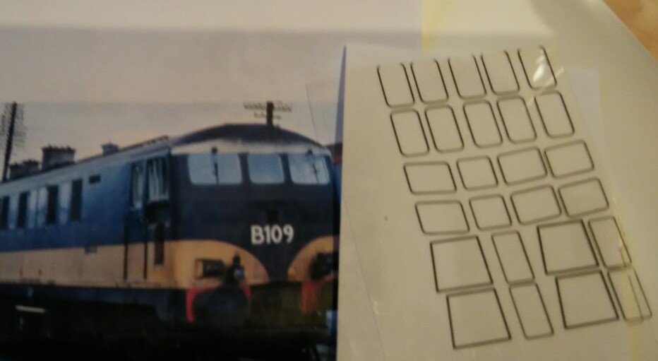
Right so, a rhomboid shape and not a regular rectangle?
-
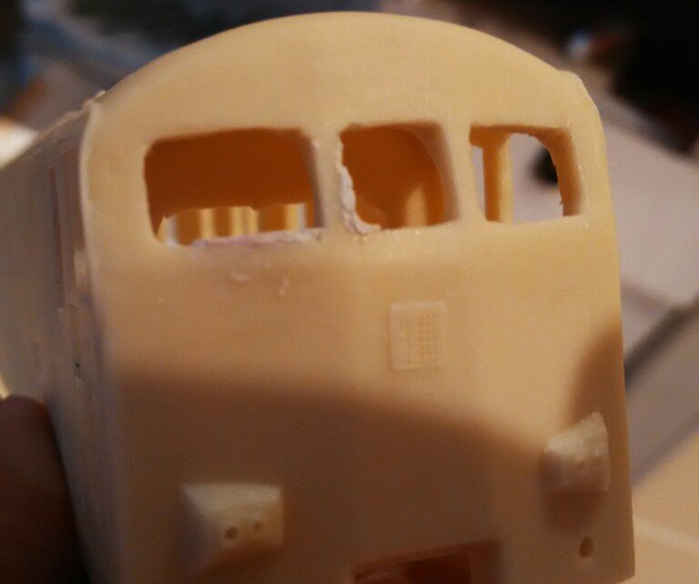
Started on the body, with a bit of filling and filing of windows and frames:
The thing I'm confused by are the cab front windscreens: the SSM cutting guides suggest the outer pair are slanted, but all the photos I'm seeing suggest that they are perfectly straight:
-
I'm just after getting a massive power cut here. Whole streets affected.
Merry feckin' Christmas.
-
Sharp intake of breath after that photo....what a loco.
....and difficult to get spares for if anything goes wrong. I've tried.
-
That's knocked four moves off mine.
-
Will 21mm be an option on your custom-made DARTs?
-
(Ten hours later)
Think I've found a couple of other sources of the 12T and 20T spur gears; not too expensive.
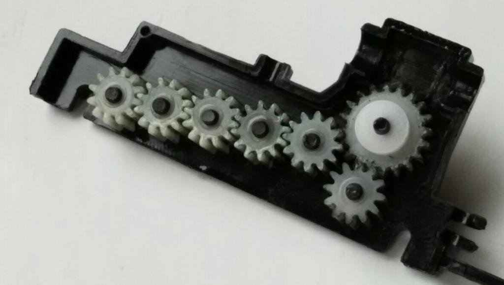
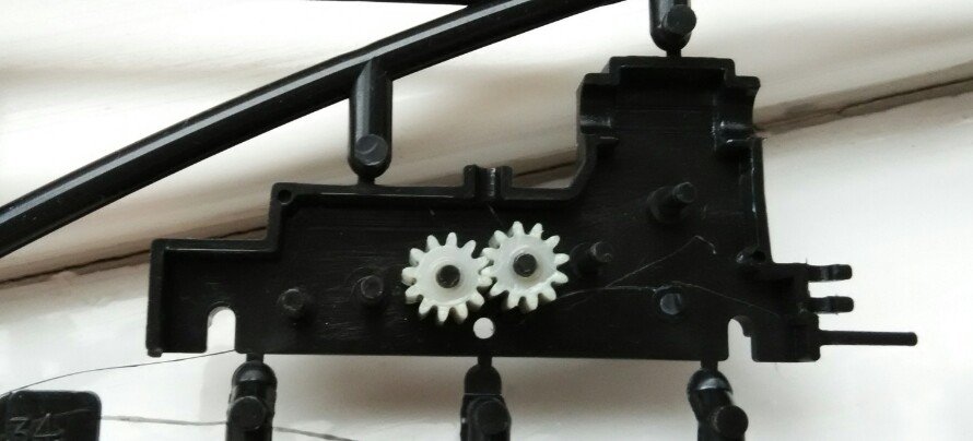
Original Heljan Hymek geartrain looks like this:
....whereas the room left for a centre axle on the Sulzer bogie looks like this:
A bit close to the idlers.
-
Hi Horsetan
I have to agree, that extra 5mm makes a huge difference, got to make myself one of these! if I can find the time and use the correct rails which should enhance things more!...
If ye're near the South Dublin MRC, I wonder if they'd give a lend of Adavoyle Junction so that your DARTs can be test run on all facets of 21mm gauge.
-
What was the answer to your Longford shunting puzzle in the end, John?
-
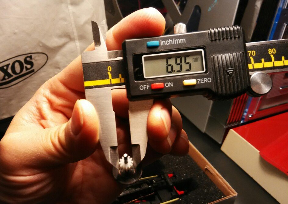
Elsewhere, I think I've partly solved the problem of obtaining those Heljan plastic gears. Fingers crossed.
The Heljan cog has 12 teeth, and has an overall diameter of about 6.95mm. Not sure what DP or MOD type it is, though.....
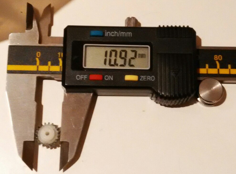
The large Heljan cog (the initial stage driven by the worm) is 10.92mm overall diameter, and has 20 teeth.
Bill Bedford reckons all Heljan gears are 0.5MOD.
-
Brilliant.
-
Looks so much more convincing on 21mm.
-
Nollaig Shona Duit.
-
....Task
1.Stable coaches clear of main line.
2.Couple on to Liner and position train in the loop for departure to Dublin with the least number of moves.
[ATTACH=CONFIG]21870[/ATTACH]
Are we to assume that the loop is not long enough to hold both commuter and liner, and that the molasses must not be touched?
1. Draw commuter train forward towards Dromod, clear of points.
2. Set back train into loop. Uncouple.
3. Run forward towards Dromod, clear of points.
4. Set back into liner road and couple to liner.
5. Draw forward towards Dromod, clear of points.
6. Set liner back into main line. Uncouple.
7. Run forward towards Dromod, clear of points.
8. Set back into loop, couple to commuter.
9. Draw forward towards Dromod, clear of points.
10. Set commuter back into liner road vacated in 4/5 above. Uncouple.
11. Run forward towards Dromod, clear of points.
12. Set back and run through loop towards Edgeworthstown, clear of points.
13. Set back onto main. Couple to liner.
14. Draw liner forward towards Edgeworthstown, clear of points.
15. Set liner back into loop.
End.
I'm sure the whole thing could be done in fewer moves if there were enough space on the cem&fert line.....
-
Yes
The future of marketing and merchandising is assured.
-
Will there be Episodes 8, 9 and 10?
-
....There's barely one post I don't have to edit...
The upside down photos episode was funny, though.
-
I was thinking DJH to be honest!
'tis a start. But would you be completely happy knowing that something better exists....?
-
If I had the cash I would've bought that princess kit, to put by till the skills were good enough to build it. ....
I sold my oul BMW to buy the Brassmasters Princess last year. It was worth the sacrifice.
Michael/Judith Edge's Princess etches are still available at £45. Brassmasters say they will still sell the detail castings from their Princess kit separately, and may still produce spare etches if needed.
Will the brassmasters offering of the coronation cater for the Ivatt variant?....No. But there's nothing stopping ye buying the Comet Ivatt detail/conversion kit (LDP08) and adapting it to work with the Brassmasters..... Sure there'll be people trying this.
-
God Almighty, the shunt manoeuvre possibilities are messing with me head!
-
Oh dear Gentle Lord....swoon, flutter, weak at the knees etc. etc.
That is just glorious. It's one thing to build it, but can you imagine the r&d to get that stuff to market???
Glorious.
And the website is completely functional, does exactly what it says on the tin, no scrolling, just two clicks and you're there.
I detect Des raising his game even as he wrote that....
'tis not easy being SSM - he has to be Malcolm Mitchell+Martin Finney+Brassmasters+Masokits for all of Ireland.
Having managed to acquire samples of much of Brassmasters' loco kit range over the years, their artwork is good enough to frame and go on show at the National Gallery.
Des, there's still time to snap up the very last Brassmasters Princess kit if further inspiration is needed. They only produced 40 kits. Once they're gone, they're gone forever.
-
Jeepers , Noel, from a man that said to me last year that you couldn't be bothered with " kits" you're going to be a busy bee with all the ones lined up in front of you.
"When my information changes, I alter my conclusions. What do you do, Sir?" (John Maynard Keynes)
-
Elsewhere, I think I've partly solved the problem of obtaining those Heljan plastic gears. Fingers crossed.
The Heljan cog has 12 teeth, and has an overall diameter of about 6.95mm. Not sure what DP or MOD type it is, though.....
-
....Keyboards can disguise the generosity of spirit .....
'tis a feckin' good disguise.
Here you go garfieldsghost, I'll leave the ceremony up to you....[ATTACH=CONFIG]21866[/ATTACH]
Would that be the same size as the one Ted won for the "Three Elvises Act" in the Priests' Talent Show?

Sulzer Kit
in Irish Models
Posted
The SSM glazing template looks like a rhomboid.
I must be going mad.