
Mayner
-
Posts
4,855 -
Joined
-
Last visited
-
Days Won
119
Content Type
Profiles
Forums
Events
Gallery
Blogs
Store
Community Map
Posts posted by Mayner
-
-
The ulterior motive was probably to keep herself distracted while I decided whether to dismantle or re-build the N Gauge layout. The layout had successfully survived a move from Ireland to New Zealand in 2004 and I had started to incorporate it into a new larger layout in Auckland before a move to the Waikato in 2007.

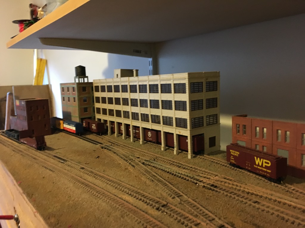
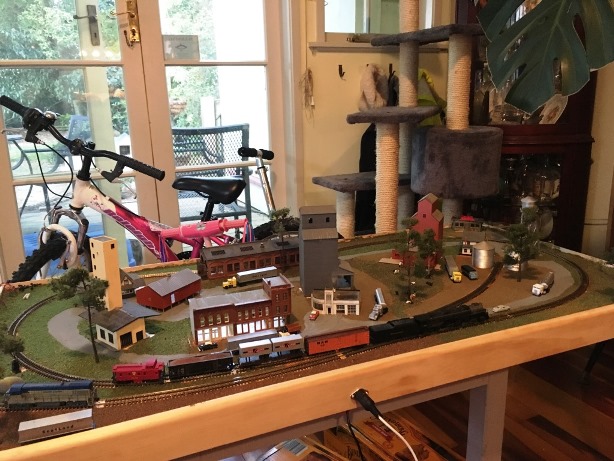
The downtown area still looked fairly good though ballast and ground cover could do with improvement. The track is Peco Code 55 laid on cork with Woodlands Scenic ballast on 15mm ply base and drums like hell.
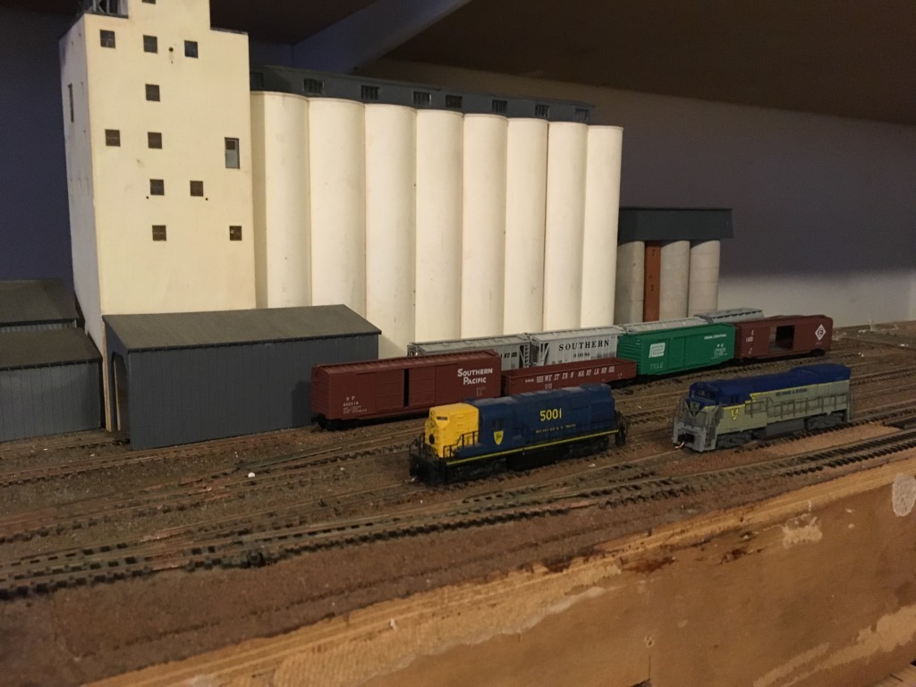
5001 (Yellow & Blue) was my 1st N gauge loco an Atlas/Kato RS11 bought in 1988 in Norfolk & Western black, 5001 is currently available from Atlas in the Yellow Nose Scheme. The second loco a U23B has a cut down Kato U30C body on an Atlas/Kato U25B Chassis and excellent runner. Atlas brought out a highly detailed U23B around 2006.
The layout was originally designed to fit a box bedroom in Dublin and additional boards added for a yard. I had scrapped one of the yard boards and lifted the track on the second and now planning to re-lay.
General view of the downtown models with a train entering the yard. The idea was to represent a yard served by two separate single track main lines and different railroads.
-
 1
1
-
-
I managed to complete some of the long list of half finished jobs over the Christmas and holidays including re-instating DCC trackpower on the garden railway and tidying up the area around the loco yard. Hopefully this will free up time at some stage to finally start an Irish layout in the garage.
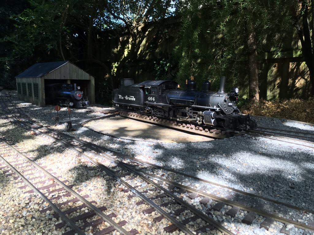
464 on turntable 20 on shed.
The turntable works nicely but is a tight fit for 464. Basically a length of decking pached on washers pivoting on a coach screw
One of the jobs was to convert my old Bachmann 4-6-0 to on board battery control and a repaint in satin black as my stash of Floquil Dirty Black with its nice bulish tinge had finally run out. The loco derailed while on test rolled over and I ended up having to re-build the cab. I am planning to decal and varnish the loco before weathering
Loco yard
I have tidied up this area ballasting the track with 6-8mm washed pebble and levelling the area between the lines with screenings. The whole lot is then glued with a 50/50 concrete bonding agent water mix with a drop of isopropyl just like in the small scale.
This should reduce the build up of leaves and debris between the tracks and prevent the stone being washed away by rain. I am planning to build a coal tower beside the little shed which has stood up to 7-8 years in the weather
-
1
-
-
The numerous Irish Railway Pictorial books published in recent years by Ian Allen are probably the best reference source for steam hauled passenger trains. The Great Southern Railways and Great Northern albums are among the best as they cover both branch and main line trains over both railways systems.
While modellers and enthusiasts tend to be fixated with whether the coach was GSWR, a Bredin, Laminate, Park Royal or Craven the operating people were mainly interest in the class of passenger, number of seats and whether it was a corridor or non-corridor.
It made not a whit of difference to the operating department whether a 64 Seat Corridor 3rd was a GSWR,, MGWR, GSR or CIE coach once it was fit to run.
In addition to 3rd Class the majority of steam hauled trains included 1st Class accommodation, besides a van and 3rd class carriages a composite or 1st class car would be required even on a humble branch mixed train made up of one or two coaches.
-
Patrick, Stephen, Fran & Richie do you intend continuing with the crowd funding model for the Tara's and new models planned? Funding models up front from your own resources is one hell of a financial risk, MM Cravens were beautiful models but took one hell of a time to sell out.
-
I suspected that centralized distribution was not necessary. Lots of old photos of churns on the platform awaiting pickup, at least when branch lines existed. Great map by the way
Milk in churns was likely to be restricted to stations in dairy farming regions in the North East & South West and likely to be pretty rare elsewhere.
The GSWR had 12 Milk Trucks 736-738 & 742-750 which were all withdrawn in GSR days all had gone by 1941. The GSWR Milk Trucks appear to have been basically a passenger rated 3 plank open with cupboard doors. One of these loaded with churns would look the part behind a 101 or 60 Class at the head of a train of GSWR 6 wheelers.
I always thought a small Co-Operative creamery with a queue of small farmers delivering milk using donkey carts, Ferguson tractors, VW beetles and Morris Minors would make a nice cameo scene on a layout set in West Cork, Cavan/Monaghan .
Some of the creameries were large enough to have a private siding to send out butter by rail, the dairy at Rathcoole in Country Antrim was sending out enough traffic to keep the Ballymena-narrow gauge lines in business into the late 1930s after iron ore and excursion passenger traffic died out.
-
The GSR used Carriage Trucks to transport road-tank wagons similar to those used to carry beer & milk in the UK http://mike.da2c.org/igg/rail/11-kitba/rrtank.htm. Carriage Trucks were basically low sided passenger rated 4 & 6 wheel flat wagons originally intended to carry horse drawn vehicles, later used to carry cars and vans.
There is a photo of one behind a D17 on a Cork passenger train at Limerick Junction in the May 1955 Railway Magazine. I will scan and post when I get a chance.
There was little opportunity for bulk milk traffic to develop in Ireland as most of the major cities are in or near to excellent dairy country. The transport of raw milk by rail is viable in New Zealand due to a combination of amalgamations, plant rationalisation, tonnage and line haul distance.
-
Nelson. Nice to see you jumping in at the deep end and fabricating your own W Irons for the 6w van. Practice with the piercing saw and your soldering it will open up endless modelling possibilities. I stlll have the saw I bought nearly 40 years ago unfortunately I don't use it to the same extent as when I was in my teens & 20s. Keep up the good work
-
By the way, Glover, your "plan" to build a GN terminus in Sligo ain't a million miles from others' ideas. Ballyconnel Road is / was on such a line - pity it's 3mm to the fut, otherwise you could join the lot together.
Happy Days!
This happened before with the Dublin & Drogheda and the Ulster Railway setting out to build a railway to two different gauges fortunately they kept to the same scale
To confuse things further David Malone has built a model of Cliffony on the MGWR line to Bundoran to 21mm gauge S4 standards. Photos of some of David's models including Cliffony station & signal cabin appeared in the short lived Rail Model Digest in the 1990s. Funnily enough the buildings bear a striking resemblance to Dromad.
-
1
-
-
Leslie, he'd need 150 "H" vans for them to pull, plus about 200 GNR vans - maybe you could give him 350 for the price of 349? :-)
In reality, CIE did offer at one stage to take over the entire GNR, so the idea of CIE all over Pettigo is by no means far fetched - in fact it's a very credible "might-have-been". If that had happened, it's very probable they would have eaten the SLNCR too, so "Arigna Road" would all have to be repainted (sorry David!!). That would probably have resulted in C class locos taking a three-times-daily mixed from Sligo to Enniskillen, maybe on to Omagh. Thus, the GNR Western District would have its own way into Sligo.
Would the SLNCR's Railcar "B" have ended up in green on the Fintona branch?!
Had all this happened, and especially had there never been a border, while much that actually did close would have done so anyway, it's at least possible we would still have the Derry Road, and Enniskillen - Clones - Portadown and Dundalk..... that's for another day!
It would be interesting to find out how serious CIE/Merrion St were about taking over the lines. By all accounts both Transport Ministers had a good working relationship and Merrion St was beginning to think in similar terms about the railways to their northern counterparts.
The closures worked pretty much in CIEs and the Irish Governments favour by closing down a competitor and diverting cattle traffic away from Belfast & Derry to Dublin Port, so there seems to have been an element of realpolitik on both sides.
There was a proposal immediately before closure (prompted by the shippers) for the SLNCR to take over the Ennskillen -Omagh line as a "siding" for cattle traffic from Colloney, theB101 Sulzers would have been just right for the job if Waterford would part with one!
-
Nice what if the Bundoran line had of reached Sligo or if Merrion St had taken up Stormant's offer and taken responsibility for operating the GNR Border lines and making up the losses in 1957
Very atmospheric I am pretty much hooked on eye level baseboards the Bullhead track really adds to the effect. Are you planning to add any GNR locos and stock? The Bundoran Express with a OO Works U Class & 4 modern GNR coaches would be a real eye catcher & a nice contrast to the drab CIE greys and greens.
-
Its hard to believe that IE are still relying on hand signals for shunting 20-30 year after most railways including British Rail adapted 2 way radio communication, especially in a yard like East Wall with curving roads where its difficult to maintain a clear line of sight between the driver and the shunting crew on the gound.
The shunter controlling the move should have signalled the driver to stop 1-2 wagon lengths back from the Liner until he (the shunter) could accurately judge the distance between the Liner and his cut of wagons.
In the States & New Zealand the brakeman or shunter unsually rides on the end car to reduce the amount of walking, chopper or knuckle couplers have largely eliminated the risk of being squashed between cars while coupling up.
-
Outdoor soldering station
I made up a soldering iron stand from a piece of 6x2 and an old Litesold stand after picking up the iron by the hot end
.The minidrill was for rail cleaning but a piece of wet and dry turned out to be less bother. Container is a rust convertor diluted 50% with water, worked a threat.
The leads are fed through an ELCB just in case I do something stupid with the cable.
Not terribly clean rails.
Tinned
One I did earlier.
Allowing for expansion s important, I had joints fail where I did not allow enough. I use an LGB graphite paste for lubricating the fishplates when 1st laying track, which also helpe to maintain conductivity.
-
Although large scale I thought this might be useful for anyone considering or using DCC
I recently restored track power to the garden railway after a major re-sleepering programme. Basically I have had to replace about 50% of sleepers on the main line after 7-8 years use as a result of UV damage. Although most of my locos are now battery electric, I though it was a good opportunity to upgrade the DCC system rather than converting all of my locos to on board battery power.
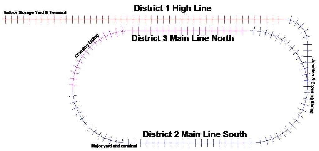
Schematic of railway showing power districts
The main line has a 2% ruling gradient, the High Line 4% which limits loadings and results in high current draw from locos climbing the grades.
I divided the Large Scale layout into separate power districts protected by DCC Specialties Power Shield PSX1 circuit breakers. These both protect the DCC Command station and avoid shutting down the entire railway in the event of a short or a loco de-railing and should simplify trouble shooting.
Control system for Large Scale Digitrax DB150 ampmeter, Radio & IR receivers and DPDT isolating switches for Power Districts
The circuit breakers have basically eliminated the need to return command stations to Digitrax for in service fault repair.
The circuit breakers are fed through DPDT switches bought from Peats of Parnell St about 40 years ago, the circuit breakers and Digitrax Command station was used on a layout in Dublin before moving to New Zealand in 2004. The radio receivers and radio throttles were bought about 5-6 years ago when we moved up from N to G Scale
Circuit breakers behind panel
Hidden away beneath the N Gauge.
The DCC control system for the large scale layout lives on a shelf below the baseboards currently used to support the N gauge.
The biggest job was the bonding of rail joints, most of the rail is heavily weathered after 9-10 years use in the humid Waikato climate. The Code 250 brass rails are used to conduct power rather than a parallel power bus, wiring between the shed and individual blocks or power districts is by a combination of mains and outdoor low voltage cabeling.
I clean the web of the rail using 240g wet and dry, and use a cheap 70watt soldering iron with resin cored electrical solder. I use a drop of phosphoric acid flux (10-15%) diluted from a liquid rust convertor (28%) as a wetting agent which improves the flow of solder. The Waikato rain neutralises the flux.
-
I am not sure why you are considering scratch building when most of the common GNR & CIE wagons are available in kit form or RTR.
Provincial Wagons produce some very nice kits and rtr models of GNR (I) wagons including the standard covered van, cattle wagon, 30t brake and bread container wagons. The CIE H van & Corrugated Opens are also available http://www.provincialwagons.com/2.html.
SSM (Weshty) of this parish produces a nice whitemetal model of the standard wooden framed open wagon used by the GNR & GSR/CIE http://www.studio-scale-models.com/Freight.shtml#
-
Who has possession of 18T at the moment?
As far as I know 18T is still on the Pine Creek Railroad in New Jersey along with C&L No3 Lady Edith.
The Cavan & Leitrim have a pair of complete but un-restored T&D coaches rescued from a builders yard in Callan in the carriage shed in Dromod. Lady Edith and her train was restored and operated for several years after arrival in the United States nearly60 years ago and no doubt a major overhaul/rebuild costing the best part of $250k is required to restore the train to service
-
Wow!
David you are fast worker David! I like the DAS clay on foam board for stone buildings.
Will the station building be in brick similar to other CVR stations or was Fintona built I stone by a local company?
-
Laying track today, it is hard work.I'm boring a hole under each point for connection to whatever system of point control I'm happy with.
Great to hear that you have started tracklaying?
Post 240 on this RM Web thread will give you an idea of the work involved with installing working point rodding http://www.rmweb.co.uk/community/index.php?/topic/76110-moving-coal-a-colliery-layout-in-0-gauge/page-10
-
Interesting.....just goes to show that rural station can have a busy life if a decent service is provided.
Roscrea Parkway? follows a similar pattern to the UK rural station with good road connections serving a reasonably well populated hinterland with a number of reasonably large villages and towns and villages. More convenient to catch the train at Ballybrophy than drive to Portlaoise of Dublin or use the Nenagh Branch
-
1
-
-
Tell them that it is just like doll's houses, but smaller and in a community setting.
That's it exactly our daughter got a great kick out of the Thomas and Chuggington wooden railways at the railway museums and tourist railways we visited in the States last year, the sheer hands on playability factor.
Smaller kids particularly girls incorporate the railway in their imaginary play giving the locos, cars trucks and animals personalities. Since we got the signals working the Sheriff's car is busy going around keepin law and order handing out citations to the other cars and trucks on the layout and even the poor John Deere tractor and the loco for a SPAD
-
1
-
-
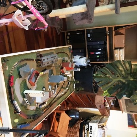
Last week my daughter Skye asked me why she could not run train on the N gauge layout I have stored in the garage for the best part of 10 years. Rather than try and get the layout up and running I thought it was a better example to follow Dave's example and build the layout under a Lend-Lease arrangement in return for running powers at some future date
Skye turned out to be a good project manager (cracking the whip) we had trains running after one evening and most of the scenic complete after 4 days. Dad was responsible for the civil engineering, trackwork and electrics, herself taking charge of town planning, scenics and the raod transport side of things.
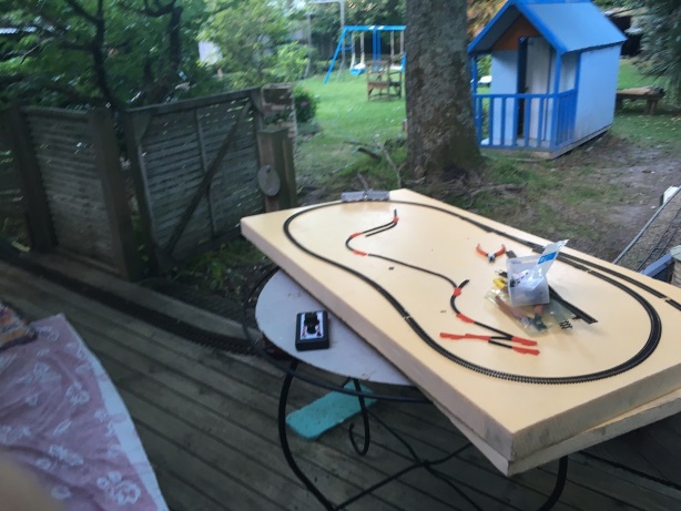
The Beginning a sheet of foam board and some Peco flexi track
I bought a 4X2 sheet of foam board about 3 months ago for a mock up for a 4mm layout, I used Code 80 Flexible track for the curves because I already had the track in stock and had no set track. Track is pinned down to the foam board with Peco track pins which was interesting.
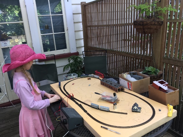
Town planning complete and test running
The points are large radius because I sold my stock of medium points about 2 years ago, I have a diamond crossing stashed away somewhere for a overlapping spur but cannot find it. Skye likes to park the loco overnight in the loco shed 1st time its been used for its intended purpose in over 20 years.
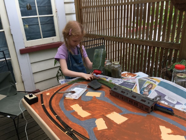
Day 3 I think Skye applying Woodland Scenic ground cover on dilute PVA (Art Attack Glue!!!) after paint dried
Nearly complete! Trying out 25 year old Con-cor Rivarassi Challenger
The real controller Babuska also keeps an eye on the Large Scale layout
-
3
-
-
There is a lot of work in setting up a working point rodding system on a OO gauge mode.
Personally I would a wire and tube or push rod system described by David under the baseboard and the Wills cosmetic point rodding above the baseboard. http://www.hattons.co.uk/62545/Wills_Kits_SS89_Point_Rodding_Kit/StockDetail.aspx
-
At first sight I though you had used one of the SSM open wagon kits. Looks really convincing
-
LQG109 shunting at Omagh North 1954 Photo N W Spinks
No obvious ballast shoulder in the area in the area between the signal cabin and platforms where staff were likely to be walikg plus all important cinder path from cabin to platforms.
It looks almost like the goods shed was re-roofed and the high gable wall with the 3 arched windows cut down at some stage after the 1954 photo
-
Indeed, Sulzer!
I suppose, to be fair, they can't get it right every time...!
CIE originally planned to operate the Supertrains & MK3s as push pull sets, even getting to the stage of building a MK2D driving cab mock up but it never happened because o funding restrictions.
The Park Royals, Cravens & MKDs had similar service 30+ years life to GSR built stock.
Replacing the MK3s with Rotem's made sense in the same way as the replacement of DMUs and loco hauled stock on Regional Lines in the UK in the 1980s with Supersprinters which allowed a much more frequent service to be operated at a lower cost.
.jpg.b3bb36680d29205b67b7cad256b2933e.jpg)


.jpg.60c2eee09f4af5aeeaaeb2e1886698e2.jpg)
.jpg.c91e07ad782ec1eaad7a8425efaedf17.jpg)
.jpg.fd4aa08140991044a8de47bce323dea5.jpg)
.jpg.615671536fcb2d94a554d6a312d15f16.jpg)
.jpg.223c0ee9b8a4b00a65715a21f197b982.jpg)
.jpg.60e1325c1cac3c3a122decb3432c4523.jpg)
.jpg.8760460075b3a118c3d7a5f749bf39c1.jpg)


Milk Tanker wagons ?
in Questions & Answers
Posted
Not great resolution photo appears to be in CIE days no GSR number plate on loco & hungry boards on tender