.png.c363cdf5c3fb7955cd92a55eb6dbbae0.png)


Mayner
-
Posts
5,192 -
Joined
-
Last visited
-
Days Won
129
Content Type
Profiles
Forums
Events
Gallery
Blogs
Everything posted by Mayner
-

EMD GM6 locos - an Irish what-if?
Mayner replied to Mol_PMB's topic in Continental European Modelling
Well spotted JHB should have read UTA/GNR joint dieselisation proposal of 1953! 'Diesel Dawn" Colm Flanagan 2003) CH10 "Diesel Locomotives of the UTA & GNR(I) p116-120 incl. diagrams. Working in collaboration UTA and GN engineers carried out a study on how best to dieselise both networks. Interestingly 4 types were shortlisted from 19 proposals received, one diesel mechanical (experimental), two diesel hydraulic, one diesel electric (833hp Metrovick BoBo with Paxman or Crossley engine) similar in outline to a Baby Deltic!, EMD, MAK, Krupp and Harland & Wolff also tendered (too heavy, too long and too expensive!) Personally I think the 121s would have been disasterous on loose coupled Derry Road freights (poor traction, inadequate braking power), however the 6 axle (A1A AIA) version of the standard export G8 (same power as 121/141) or G12 (1200Hp) would have been a different story. -
EMD GM6 locos - an Irish what-if?
Mayner replied to Mol_PMB's topic in Continental European Modelling
An article by Peter Cark on the Victorian Railways T Class (Motive Power Magazine (Australia) Oct/Nov 2005) provides some background on EMDs development of smaller/lighter GM6,GA8 and GL8 models during the late 50s/early 60s incl. Australian adaptions built under license by Clyde Engneering. The article identifies the GM6, GA8 and GL8 as the smallest units. GM6 The smallest unit the GM6 was adaptable to narrow gauges below one meter, but all units actually built were standard gauge, Lebenon being the main customer. GA8 Described as 4 axle version of the GM6 with two traction motors running on standard 3 piece American freight bogies. 3' narrow gauge versions supplied to Mexico and largest order to 5'6" gauge to Argentinan State Railway. GA8 was the same above the frame as the "top of the line" GL8. GL8 Built with both low and high clearance cabs, the 'best known version' with the high cab version was the Irish 121 Class like most T class built to 5'3" Clyde G6B The article identifies that while no GL8s were built in this form for Australia, Clyde adapted the GL8 design for the G6B. The Westrail J (standard gauge)being the closest thing to a 'real" GL8 in Australia. https://en.wikipedia.org/wiki/WAGR_J_class_(diesel) The majority of G6Bs were the 75 Victorian Railways Y class (5'3" & std gauge) which looked much like the later T Class but running on bogies and traction motors salvaged from withdrawn electric suburban trains. https://www.victorianrailways.net/motive power/ydie/ydie.html Clyde G8B Victorian T (second order) Going back to Pauls question about the impact EMDs failure to secure overseas orders as a result of weight/axleload restrictions, Clyde Engineering developed a lighter version of the standard G8 export model mainly for branch line use in Victoria. The Clyde Engineering G6B (second order T class) appears to have entered service between June and November 1959 approx two years before the CIE introduced the B121 Class. https://www.victorianrailways.net/motive power/t347_356.html Kiwi perspective. New Zealand Railways successfully operated 3'6" A1A A1A versions of EMD standard export G12 (DA) and G8 (DB) locomotives for many years. While some light axleload EE & Mitsubishi locos were introduced during the 50s and 60s all had gone by the mid-late 80s, the poor performing EE 2-Co Co-2 DE class by 1980. In certain respects a double cab A1A A1A broad gauge version of the G12 would have been more effective than the B121/141/181 classes, higher power largely eliminating double heading, A1A bogies would have resulted in steadier riding/improved braking (especially loose coupled goods), more a case of 'what iffery" GNR(B) & CIE 1950s tenders. There is an interesting series of articles on a joint NIR/GN(B) proposal in No 2 & 3 Vol 3 (2005-6) New Irish Lines. The GN preference appears to have been for an Arn Jung 1000hp diesel hydraulic £38,675(cheapest tender) the GN comment on the evaluation "This is the only locomotive that completly meets our requirement". The EMD proposal(s) appear to have been for off the shelf G8 designs in Bo Bo or A1A A1A format price varying between £50,937 and £52,179. To long, too heavy and too costly for the GN Board and its political masters. Its likely EMD were aware of the political and financial situation in both the UK and Ireland and had to go through the motions and quote! Apart from the challenge of both Stormont and Merrion Street coming to an agreement to spend serious money on a cross-border initiative, its unlikely that the trade unions in the UK would have been exactly happy about an order for diesel locos going outside the UK. Still a G8 A1A A1A working hard on a cross-Border or Derry-Road freight would have been quite a sight and made quite a sound. -
Basically melting & fusing finely grained metal powder in an enclosed printer with a laser. Not exactly home/desktop equipment https://www.ram3d.co.nz/metal-3d-printing/ https://www.renishaw.com/en/renam-500-metal-additive-manufacturing-3d-printing-systems--37011
-
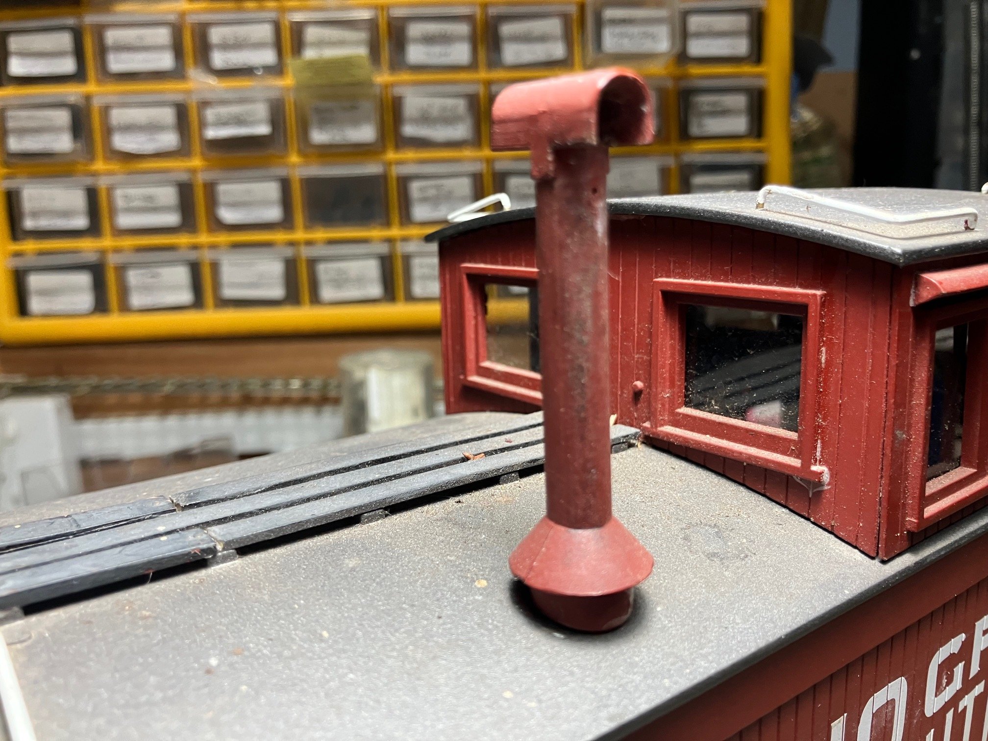
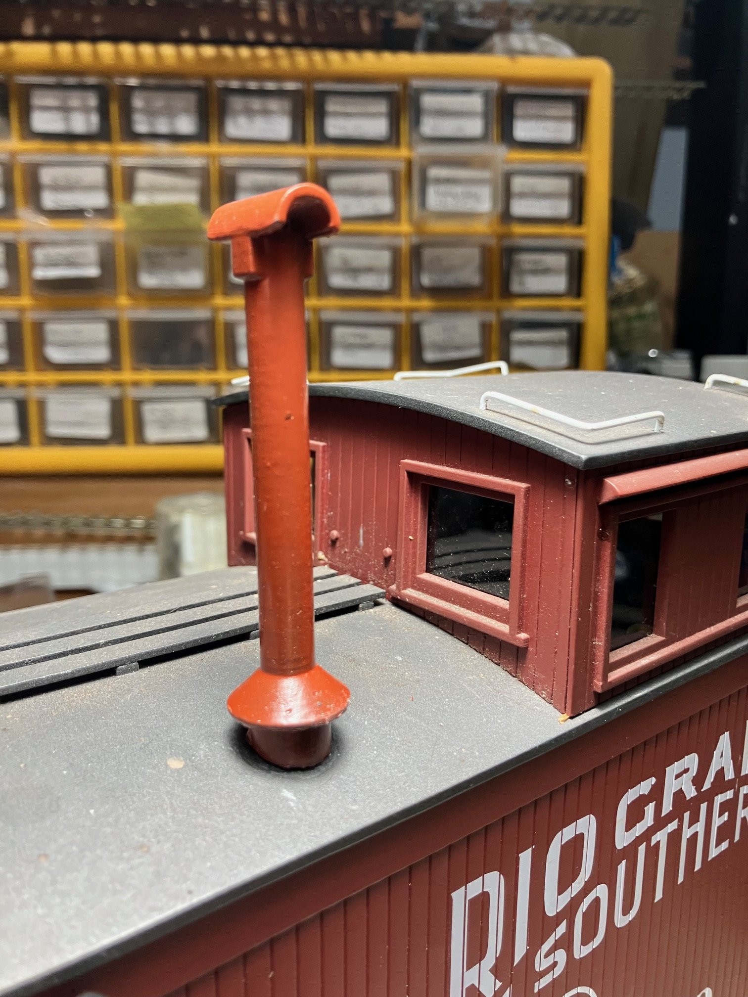
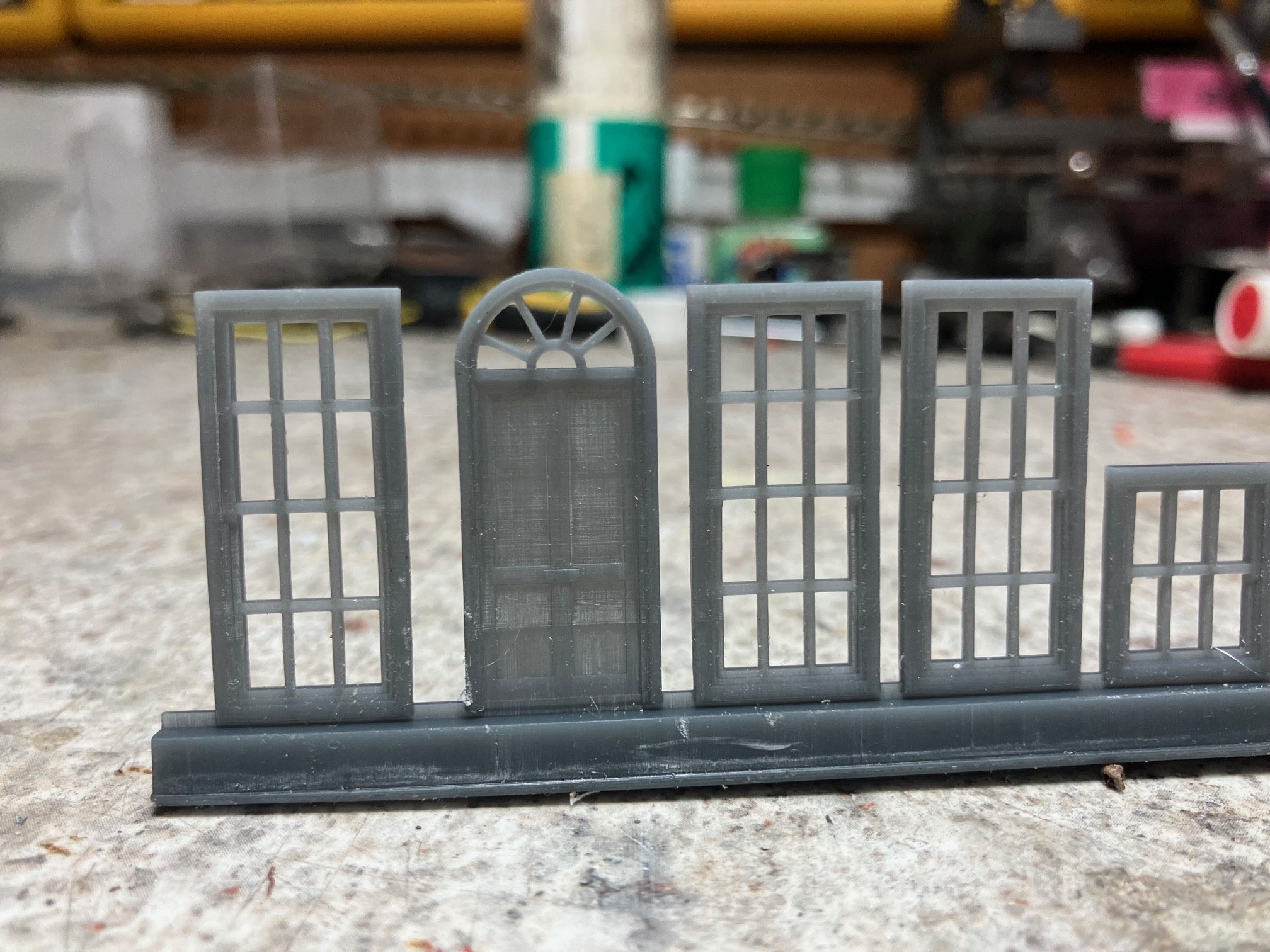
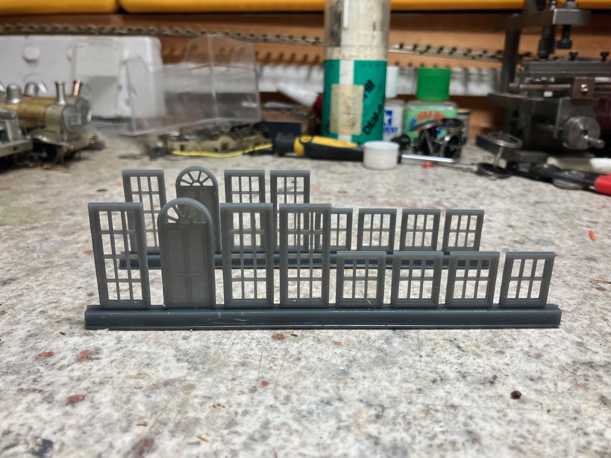
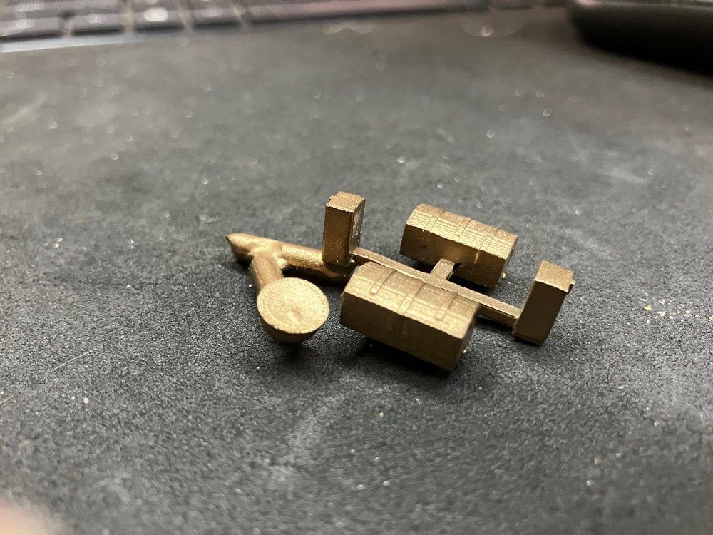
I have trialled a number of different resins to overcome the problem with brittleness almost inherent in printing with "top down" home printers. I successfully trialled Monocure 3D (Australia) 'Engineering Resins" including Tensile resin with a Flex additive and recently Impact resin. https://monocure3d.com.au/collections/engineering-3d-printing-resins. I don't know if engineering resins with similar characteristics/properties are available in Ireland or the UK I used Tensile resin with flex additive as an alternative to whitemetal to produce some of the detail parts for a 2024-5 batch of etched kits and to replace damaged/missing large scale parts including caboose smoke stacks & handbrake wheels. The original injection molded smokestack Accucraft 1:20.5 scale caboose. Replacement 3D printed stack (different caboose!) The smokestacks are quite vunerable in garden railway use two broke off/lost in recent years. Fixing upgraded to a metal pin/stud into a hole bored in the roof and bedded in silicone to try and provide some resilience. Window and doorset for a 4mm Victorian Terrace printed in "Impact Resin' The base is sacrificial to assist printing per -anunknownconsciousness/ advice. I am planning to print a wagon chassis in Tensile to see how it compares with commerically printed chassis. 3D Modelling/Printing in metal? Lost wax (invesment) brass castings prepared from 3D models. The brass detail castings (buffers, sand/tool boxes & tank filler) for my GSWR 52 Class kit were prepared from 3D printed (Shapeways) masters (2019?) These days I would simply send the 3D Model (CAD) direct to the casters who would print the master in a 'burn away' resin rather than wax! I have used Morris & Watson a locally based caster who supplies to the jewellery industry, and kit/model suppliers. https://morrisandwatson.com/ I would expect that similar casters exist in the UK. 3D printing in Aluminium. I use(d) Facfox https://facfox.com/# for the commercial printing of kits and rtr wagons with their SLA-abs-like resin. I found their prints quality and customer service to be to a consistent high standard and pricing (incl shipping) highly competitive compared to local and UK based suppliers. NZR 9mm scale modellers (O gauge track-3'6" gauge) have have produced 3D printed aluminium drive components including , gears, flywheels, gearbox casings.

-
Narrow Gauge in the Rockies not quite
Mayner replied to Mayner's topic in US / Canadian Railway Modelling
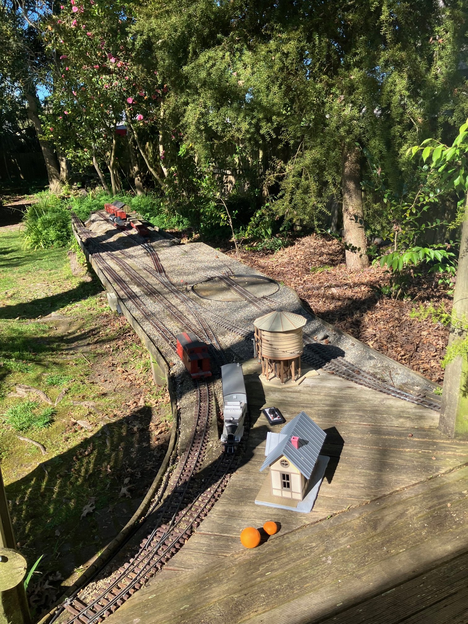
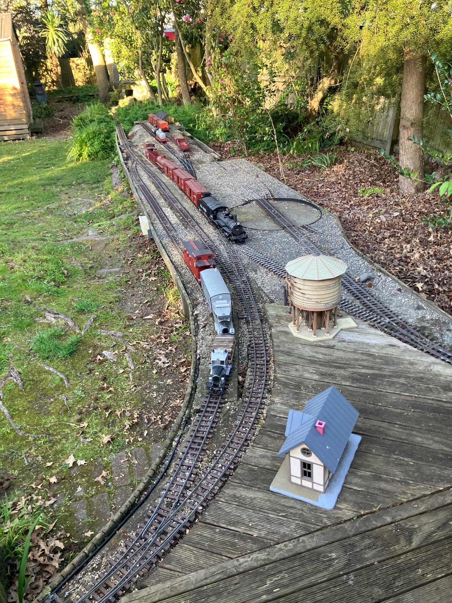
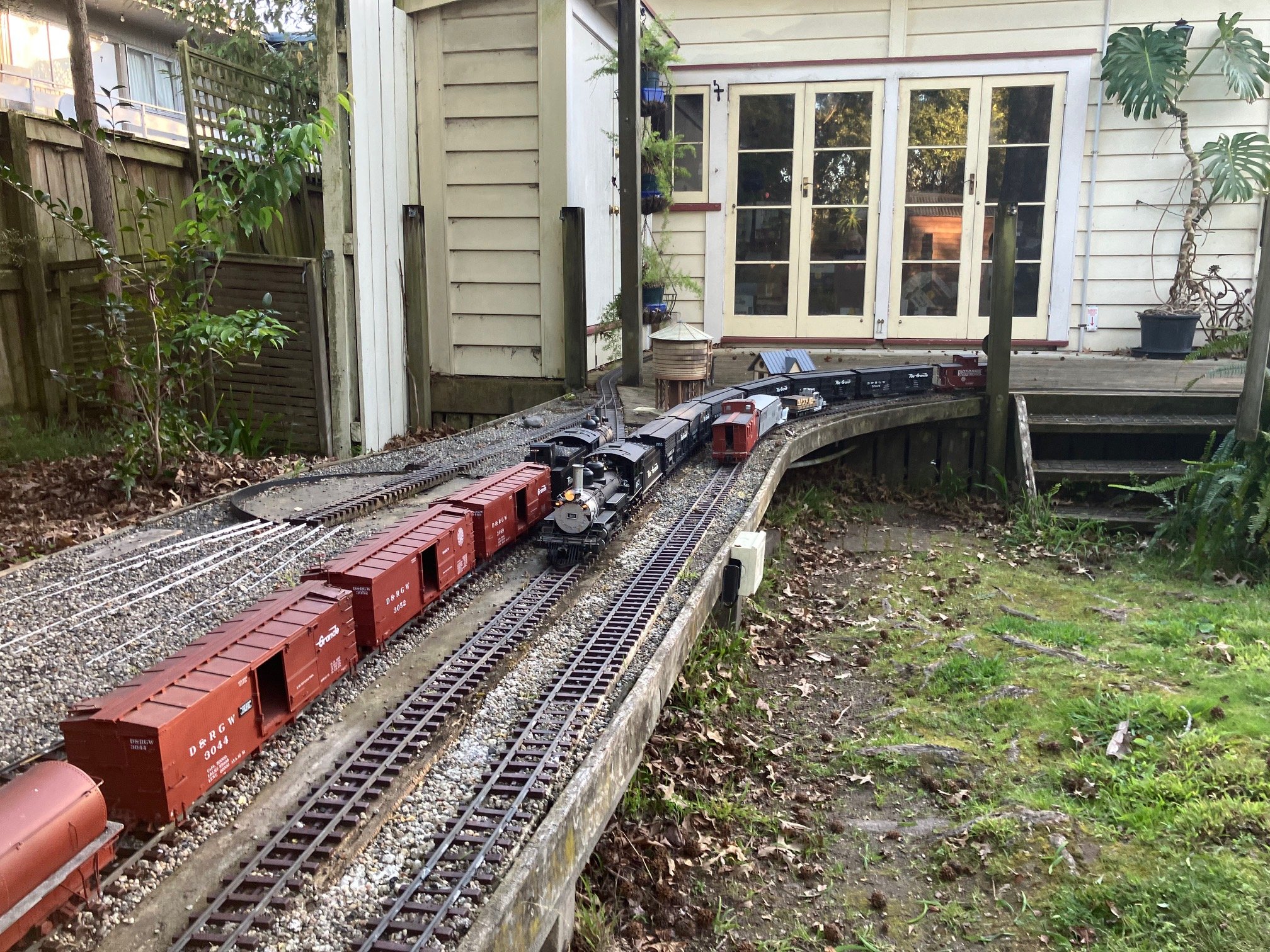
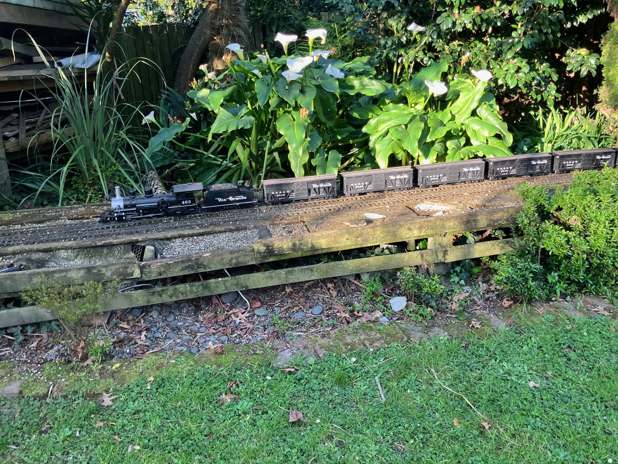
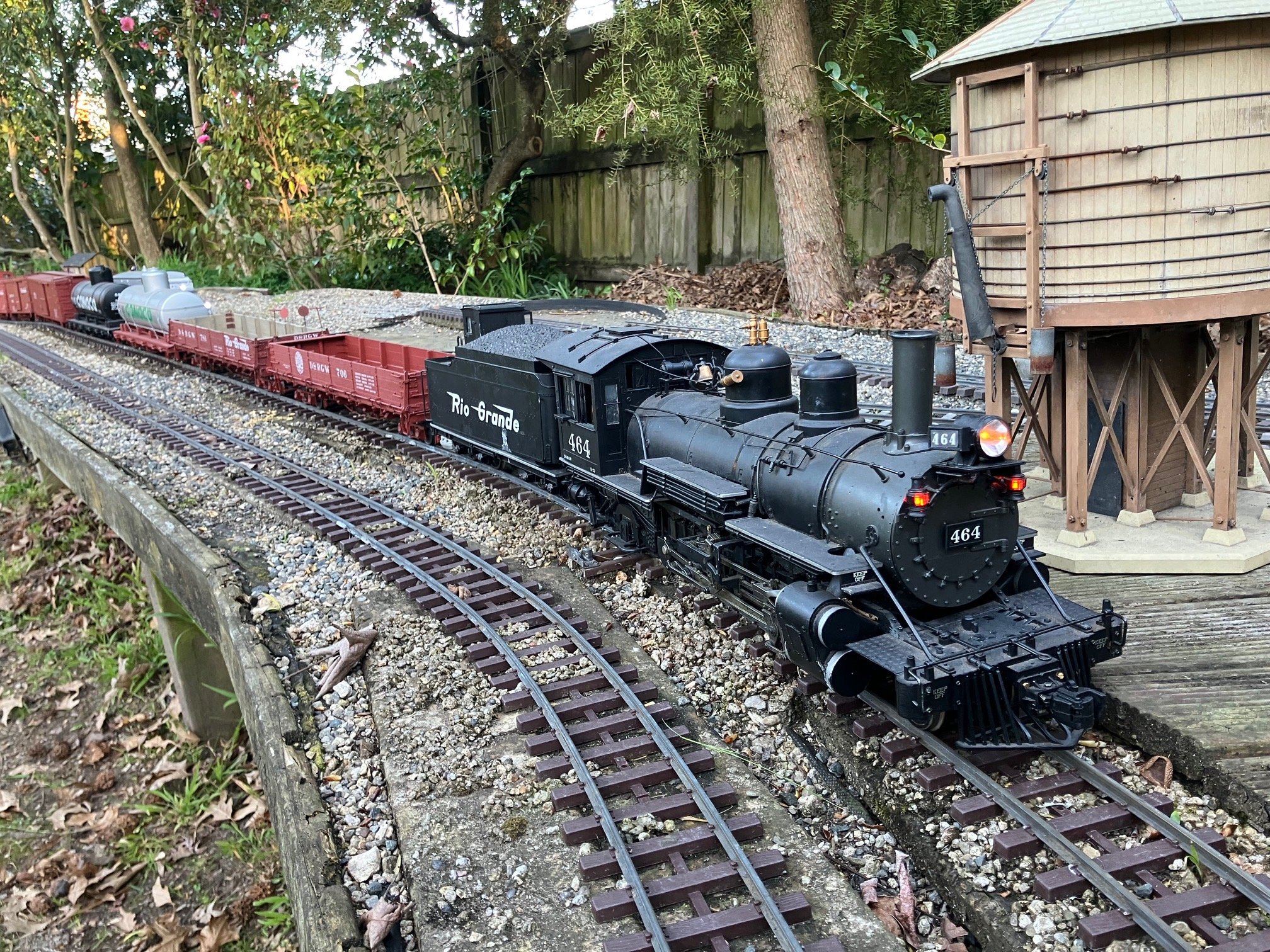
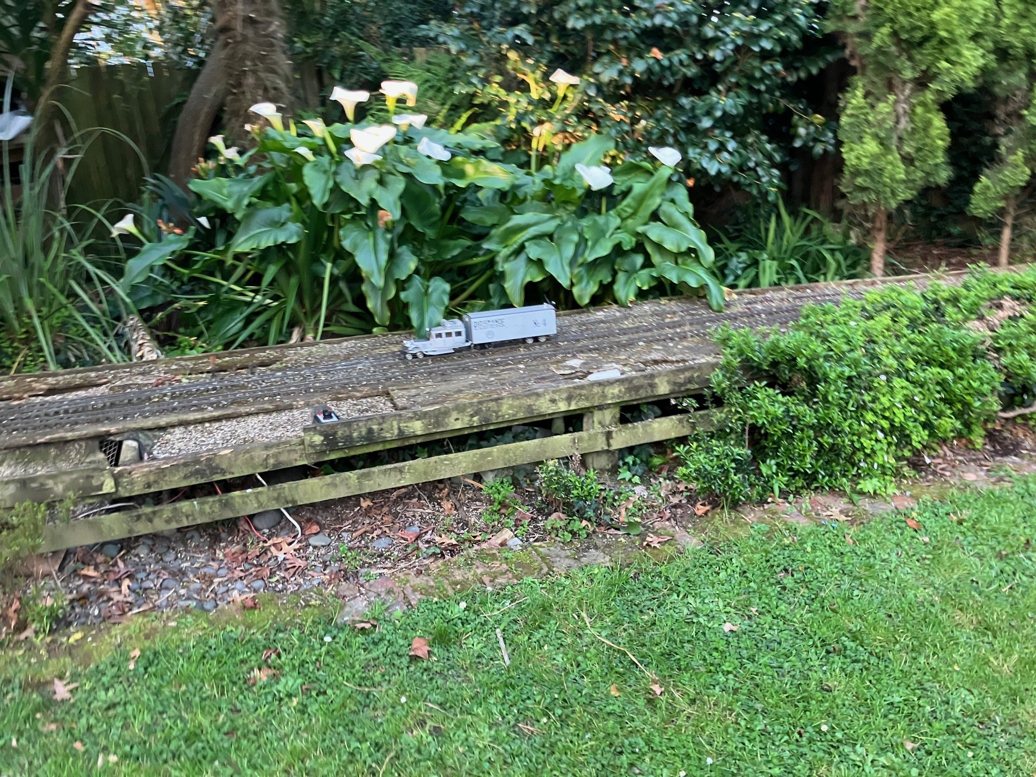
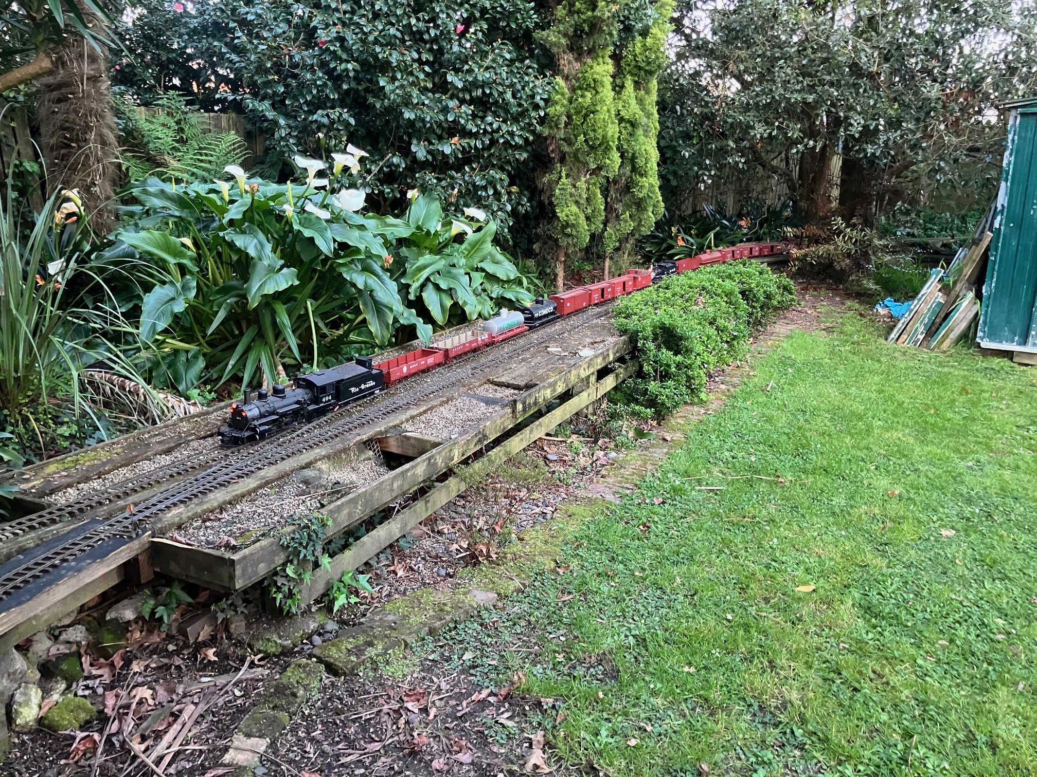
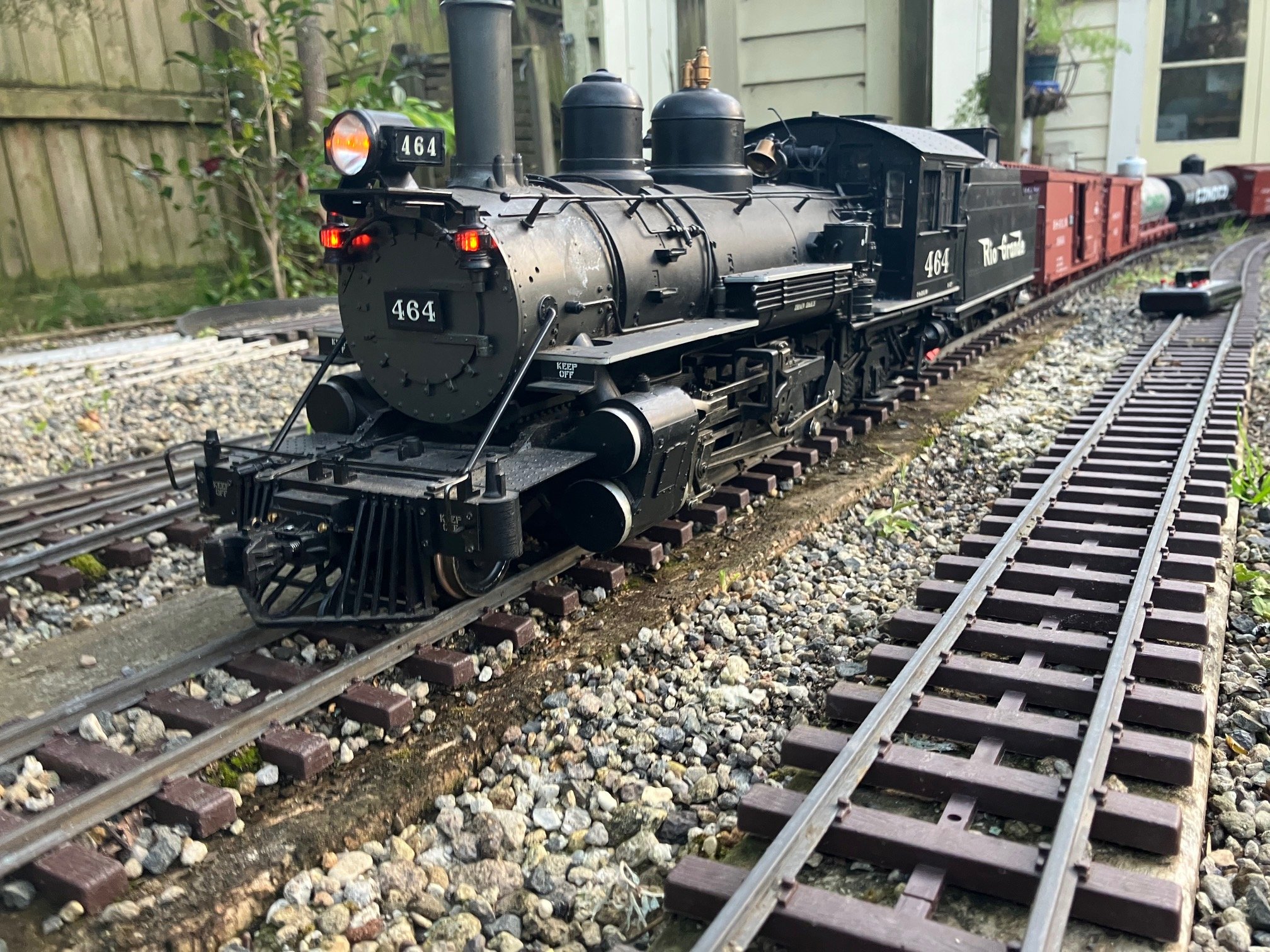
Spring seems to have finally arrived and had some work to do in the garden so good excuse for a running session. General view Jackson City RGS Motor #4 with the daily Passenger-Mail-LCL (sundries) service. Orange and Mandarin had fallen from trees in our garden (still on trees since Autumn!) Just about finished clearing (autumn/winter) plant debris (mainly leaves) from lawns and paved areas/decks, next job to bring in a load of mulch or stone to cover beds (weed control). Garage Staging around noon! Almost everyting out on the line. Staging Pilot DRGW#50 (LGB) parked No2 road RGS Motor #6 on charge. DRGW C19 #348 2-8-0 waits its next duty. Jackson City RGS Motors #6 & #4 & Caboose in Siding, DRGW#464 recently arrive on freight waiting to switch yard. Main-line clear for Stock Special. DRGW #463 arriving with Stock Special from Arboles. Spring and Autumn were the peak livestock (mainly sheep) shipping seasons on the RGS. Spring-moving stock (by trainload) to high summer pasture for graazing, Autumn to meatworks. This Special is likely to be an empty working returning cars for cleaning/disinfection, before working another special or storage until Autumn! Age/weather is beginning to take its toll on the trackbase and ground cover in this area long overdue for an upgrade after after 16-17 years use, track in this area was upgraded about 10 years ago (sleepers replaced, points on running lines upgraded from 1:4 to 1:6 about 8-10 years ago) #464 is now handles the heaviest trains following re-wiring and replacing her batteries. Ready to depart after adding all the freight cars (8) in the yard to her train (13 inc 2 Caboose) Motor #4 over took the freight and on her way home to the Staging after tutning on the Wye. Athough I replaced her batteries about a year ago Motor #4 remained problematic, unable to 'Bind" to (programme to run with) other throttles and did not seem to be holding a charge. Seem to have resolved both problems this week now seems to be holding and tracked down the cause of the 'Binding" problem, so can now programme to run with different throttles. #464 and her freight with #346 cut in mid train about to take the High-Line to the staging. Dry sunny conditions but bitter cold about 5:30pm though had been up to 16C earlier, frost forecast overnight followed by rain tomorrow, so today was a good choice for a running session and working in the garden.
-
Best of luck with the move the basement layout! Hopefully you'll find a place for your DRGW narrow gauge. Those Aristocraft/Delton C16s are quite historic at this stage. The photos remind me in a way of our 2016 visit to Como to see tthe remins of the South Park Line abandoned about 80 years earlier. The historical groups and local landowners appear to achieved on hell of a lot during the past 10 years! https://www.southparkrailsociety.org/a-vision-for-como
-
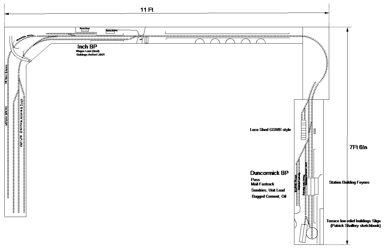
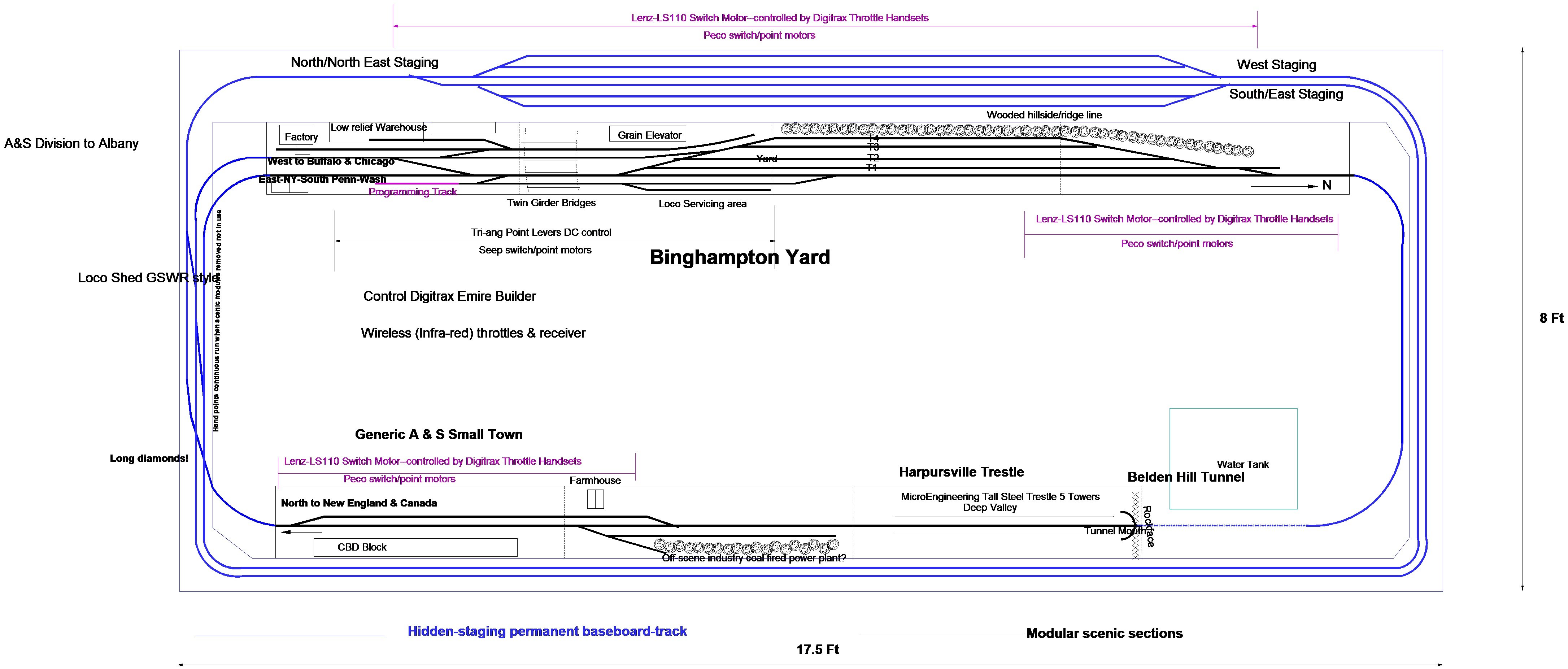
My layout building/operation appears to break down into short periods of activity followed by long periods of inactivity. Dublin late 70s/early 80s Irish Outline N Gauge My first successful(ish) layout existed for a couple of years in my early 20s in my bedroom of my parents home, dismantled following a house move. Probabably inspired by Castle Rackrent, exploring the remains of the North Kerry and an IRRS railtour to Foynes out by Athenry and home by Ballybrophy! Layout was basically an N scale 'shelf layout" on 12" boards. The terminus station was on a 5' board on a firebreast supported on the fireplace mantle piece, other main baseboards were supported on shelving brackets, though viaduct was on a lift out section across my bedroom window! Track was Peco with medium radius points, ballasted structures and scenic work reasonably advanced. Operation was based on CIE practice of the mid-late 70s, 3 return passenger services to Dublin Daily, a connection in and out of the Night Mail at Oranmore or Athenry and goods operations in transition from loose-coupled to Liner Train operation. Shunting/uncoupling individual wagons fitted with N gauge Arnold style couplers coupling could be challenging & it was even more challenging for wagons with the Graham Farish version of the coupling to stay coupled. I ended up replacing the coupling at one end of my Farish wagons with a wire hook, stayed coupled but not exactly suitable for hands-off uncoupling In the end most of the loose coupled vans ended up 'stored" around the loco shed, while the Liner (shortened Lima Freightliner wagons) worked out and back from the fiddle yard behind a 001. Regular Freights included: 1. Nightly North Wall-Duncommick Liner Bogie Container Flats +4w Guinness (Flats were shortened Lima Freight-Liner wagons-Guinness scratch built swap-bodies on std Farish chassis) 2. North Wall-Duncormick Oil Train-001 haulage-----(10-Peco 35T Tank Cars) CIE operated a twice weekly Dublin-Oranmore-Claremorris-Dublin ESSO Liner during this era. 4. Pallet Cement trip working from Athenry---6 Pallet Cement Wagons 141 Haulage--(Scratchbuilt bodies on std Farish chassis. Initially Pallet Cement for Ballinasloe and Roscommon was worked in 20 wagon fully fitted trains from Platin to Athlone, where the train was divided into 2-10 wagon portions and worked as 'loose coupled' trains to Ballinasloe and Roscommon. Ballinasloe and Roscommon were the most Westerly stations served by Platin. Galway, Tuam & Mayo received bagged cement from Limerick. Duncormick potentially served by a trip working from Athenry work worked by the 141 rostered to Mail/Pilot duties. The absence of Irish outline N gauge RTR or kits was not an issue during the era before the arrival of Irish outline models or kits in any scale. Diesel locos mainly used Atlas or Arnold chassis with scratch or modified rtr bodies, the performance of contemporary Atlas/Rivorossi, Arnold and Minitrax chassis tended to be superior to contemporary British outline rtr locos. Dublin late 90s-early 2000s American outline N Scale Oddly I didn't get round to building another operating system layout this time a division of the Delaware & Hudson "The Bridge Line" an American Class 1 Freight Railroad for about 20 years! During this time I developed and interest in American Railroads and built up quite a collection of N Scale American outline locos and stock and though it would be nice to build a small American layout 'to get something running quickly" as a diversion from scratch and kitbuilding in Irish Outline 4mm. This time the basic track layout was a folded 8 to maximise running distance and probabably more importantly run time between towns (stations) & staging on the layout. The focal point of the layout is a Yard and Loco Servicing depot where trains arrive from and depart to different destinations, sometimes reverse direction, re-marshalled, and locos swapped seerviced & re-fueled. The layout was devised in two distinct parts hidden trackage including a large staging (fiddle) yard, and portable modular scenic sections which included the main yard and a scenic section which included a small town and a long tall steel trestle. Trackage on the hidden section was Peco Code 80 (some salvaged from the early 80s layout, though turnouts were all large radius in order to achieve reliable running. One of the features of the layout was a series of crossovers to allow continuous running when the scenic sections were out of use or removed. Trackage on the scenic sections was Peco Code 55 fully ballasted with structures and scenic work reasonably advanced before the layout was dismantled before our move to New Zealand Operation was based on operating the "Symbol Freights" that operated over the system during the late 70s-early 80s. The railroad mainly functioned as a "Bridge Line' between different carriers during the era modelled, with little local traffic, primarily transporting through freight between Canada and New England (North & East) and the South & Mid-West. The yard modelled Binghampton was basically the junction between North-South and East-West routes. The folded 8 track layout had the advantage of allowing a decent running time (avg 5-7 minutes) between staging and the main yard, helping keep operators occupied. Usually solo operation there was just about enough time to run the Symbol Freights during an operation session, but not switch the Industry Tracks or cross trains at the passing station, though occasionally managed to operate a "Pusher Service" over the hill from the yard to the trestle a distinctive feature of the prototype. Interestingly visiting operators loved to run trains as fast as possible around the folded 8 at the end of a running session. Couplings were Microtrains (N Scale Kadees) and worked reliably (usually replaced car trucks (bogies) with Kadee trucks to ensure reliability, locos also fitted with Microtrains couplers. Running multiple loco consists (3-5 locos) with DCC it was simpler to match locos with similar running characteristics than attempt re-programme locos with different characteristics to run together. Postscript: I began to incorporate the Binghampton Yard module into a new larger layout following our move to New Zealand, but ended up building a Large Scale garden railway following a house move a couple of years later. I still have most of my N Scale collection (locos, stock and buildings), might come in useful if we ever have to downsize.
-
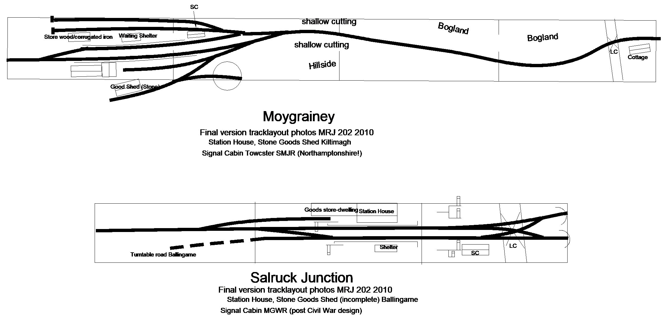
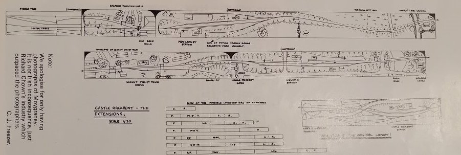
I saw Yaxbury at an exhibition in Essex during the late 80s, surprising what could be achieved in S Scale in a relatively small space. High overall standard of modelling and some interesting stock. I saw Castle Rackrent at an exhibition in Perthshire and the late Dave Walkers Killaney layout at a Chatham Show during the early 1990s. (Richard Chown inspired Dave Walker to take up 7mm broad gauge modelling and Killanney could connect end-to end with any of the Castle Rackrent modules. A final look at the Castle Rackrent system. One of the interesting features of the system was that the modules could be arranged in different formats (different exhibition halls) before moving to a permanent home opening up the prospect of regular (monthly) operating sessions) The layout/railway evolved considerably during the 30 odd years between its appearance in the Modeller (75 & 78) and MRJ 202 in 2010. Moygraney originally based on Kiltimagh (crossing loop and two sidings) was modified to include four sidings and a turntable (widening of baseboards?) and Salruck Junction evolved from a single baseboard (6-8') featuring a junction (single crossover) between WLWR & MGWR lines and a short private siding serving a mill to a Junction Station based on Ballingarne Junction between the Foynes and North Kerry lines including a complex double junction! With the focus very much on operation the buildings and scenic work in some sections. Though the railway appears to have had a functioning signalling system! I guess the eye opener for me is what could be achieved in modelling the Irish broad gauge during an era with minimal trade support.
-
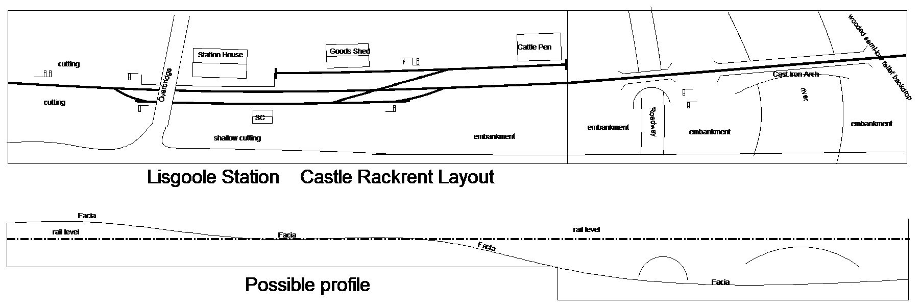
In "Fair Day at Moygraney" MRJ 202 he wrote about each station on the Castle Rackrent layout being different to gaive variety and fresh challenge every month (operating session). All started off at least based on prototypes at least in Ireland. He had found problems with some prototypes on the Highland & GNOS where station layouts were either too big, or too smimple and repetitive! Some advice lessons learned: Working in sequence there was only time to put off or pick up one or two wagons (at a station) any more takes too long for operators and viewers too. Keep sidings short: a long siding will only fill up with wagons, so easy to put them in, but not to get them out. He altered the yard at Moyganeys (based on Kiltimagh) to overcome this problem, but still a bit too big. The year attracts trains at the expense of other stations which then have to wait (nothing happening) until Moygraneys operators sort themselves out. Be carefull if considering modelling an actual station, how much of that track are you actually going to use? It may be visually essential to include certain pieces of track for example a crossover used by one train weekly, but if it has no other purpose don't model it. I found most of this advice to be true when operating my garden railway 5-6 years ago with 2-3 crews and even an N gauge American layout with 2 operators 20 odd years ago. Only real difference was we shunted/switched 1-2 large scale wagons in 4-8 wagon trains, while in N the focus was on moving entire trains/cuts of cars/wagons at a major yard rather than individual cars/wagons. Interestingly even with 2 operators and a train controller/dispatcher, we just did not have time during the operation of the N gauge layout to switch/shunt the industries on the line (Grain Elevator, Warehouse, Printworks and Coal fired power station. The operators wanted a break to just run trains round and round the folded 8 before refreshments. Anyway Lisgoole Station nicely modelled and apparently included a scenic section with a nicely modelled cast iron river bridge. The station buildings appear to be based on a standard design used on the "North Kerry" line between Newcastle West and Tralee & Fenit Branch. The track layout is similar to Abbeydorney, but apparrently based on Ferbane on the Banagher Branch in Co Offaly with a crossover between loop and goods yard via a diamond crossing of the main line rather than a crossover from main-line to goods yard. Abbeydorney became the North Kerry terminus for a short time 1-2 years during the mid 1970s after Listowel closed to goods traffic.in 76/77? The layout profile is based on guesswork as the railway transitioned from a cutting to an embankment and river crossing.
-
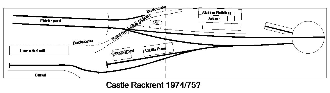
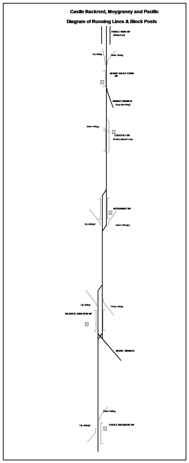
Castle Rackrent first appeared in the Railway Modeller in May 1975. A 7mm Irish Broad Gauge Waterford Limerick and Western layout with an overall length of approx 16' on two baseboards, station building based on Adare and turntable release similar to Foynes and Newcastle West. Track/layout plan is basically from memory, once saw the layout at an exhibition in Scotland over 30 years ago and from photos in magazines and https://highlandmiscellany.com/tag/castle-rackrent/ Blog. Castle Rackrent morphed into a much larger system layout and appeared as "Castle Rackrent, Moygraney and Pacific" as 'Railway of the Month" at some stage between 78-80. Moygraney was based on Kiltimagh on the Burma Rd (with extra sidings and a turntable), another station Lisgoole combined North Kerry (Ardfert/Abbeydorney) style buildings with the track layouyt from Ferbane Co Offaly and a Junction Station (with the MGWR) based on Ballingarne Co Limerick, though the buildings and scenic works on this section do not appear to have been completed. The schematic is based on a diagram from "Fair Day at Moygraney" that appeared in MRJ No202 2010. The extended layout appears to have originally 'lived' in a 100' long post office footbridge at Edinburgh Waverley Station and later re-erected in a purpose built basement at the owners home!
-
Well spotted Stevie should have been departure platform. Another little snippet from Sligo: When the Sligo-Ballysodare section was singled in the late 50s following the closure of the SLNCR a section of double line was retained from MP133½ to Sligo 134¼, the junction between and single and double track section was controlled by electrically powered points and signals controlled from Sligo Cabin. The GSWR introduced the Worlds first hand-generated electrically controlled railway Junction at Cherryville Jnt in 1924 and the GSR later installed remotely controlled junctions using similar systems at Killarney Junction (Mallow), juntion between Macroom line Cork, Clara & Banagher Junction and Inny Junction. The control system (& possibly points & signals) used at Clara & Banagher were apparently transferred to Sligo and the connection to the branch to a ground frame in 1958. Control system/points and signals used at Inny Junction transferred to Manulla Junction following closure of Cavan Branch and Manulla as a block post in 1963-4.
-
Apart from taking up a lot of space (min 8-9'X 10'6"-12' room) in order to provide access on a least three sides, small radius (setrack) curves are one of the main drawbacks with oval layout plans width a baseboard width of 4 foot. Small radius (less than 24") curves can contribute to problems operating larger locomotives (001, 071,201 & other Co Co diesels and bogie coaching stock. I experienced problems with bufferlocking when shunting wagons with an IRM 001 Class through small radius Peco points. MM 121 and possibly 141s are fine with these Peco small radius points, but forget coaches! Model railway text/planning books of the 60-70s era typically recommend a minimum 24'/2' radius in OO gauge. Increasing the baseboard length/width by a minimum of a 1' all round and incorporating an operating well would both allow to increase the minimum radius to at least 2' and potentally replace small with medium radius points while operating the layout from the well inside the same or similar sized room to an 8X4. Possibly allowing the area on the opposite side to the passing track/yard to be used as staging/fiddle yard. American modelrailroad terms "Industry" " Industries are the businesses that generate traffic for the railroad - they ship and receive goods by rail. Common model railroad industries include warehouses, factories, grain elevators, coal mines, and team tracks. Industries justify car movements and provide switching interest. (Model Trains A.I glossry) 'team track" In an Irish/UK context "Milage siding" in a goods yard that handled wagon load goods traffic loaded/unloaded by the customer. e.g. a builders merchant of builders merchant ordering a covered van load of cement, or farmer/agri merchant ordering a wagon load of fertiliser during loose coupled area. In an Irish/UK context during the traditional wagon load era 'industries" could include a loading bank for beet or livestock traffic, a small oil or County Council tar depot receiving oil/tar tank cars as individual wagon loads, a mill dispatching/receiving bulk grain or dispatching flour/animal feeds in vans as individual wagons loads.
-
I have copies of the 1960 and 1980s WTT, but not the 'hours of duty and signal cabins" Section, quite a bit of night-time early morning activity at Sligo into the Liner Train era. Sligo Arrivals: Departures 02:24 (02:30 Quay)---19:15 Dublin-Sligo Liner (T.S) (001) 05:10----------------Sligo-Dublin Pass (MO)(001) 03:05 -------------- 00:35 Mullingar-Sligo Mail (T.S) (141) 07:55----------------Sligo-Dublin Pass (2X121) 04:05-10 (04:15 Quay) 22:15 ESSO Liner (T.T.S) (001) 10:20 (10:10 Quay)---ESSO Liner (T.T.S) (001) 11:55---------------08:40 Dublin-Sligo Pas (2X121) 13:25----------------Sligo-Dublin Pass (2X121) 16:45--------------13:30 " " " " " " " 14:25--------------- Sligo-Waterford (Bell Liner Path) FO 001 20:25-------------17:00-Dublin-Sligo Pas (FO) (001) 18:05----------------Sligo-Dublin Pass (2X121) 21:30--------------18:10-Dublin-Sligo Pas (2X121) 18:35-19:10 (18:30) Sligo-Dublin Ety Cement Path (001) 19:45-------------Sligo-Mullingar Mail (141) 22:10-------------Sligo-Dublin Liner M:F Sundays: 12:35--------------09:20-Dublin-Sligo Pas (2X121) 09:20----------------Sligo-Dublin Pass (2X121) 21:15-------------- 18:00-Dublin-Sligo Pas (2X121) 18:25----------------Sligo-Dublin Pass (2X121) Freight operation Sligo acted as a railhead for South Donegal following the closure of the ex GNR) Derry-Road, the friday only Bell Path was for fish traffic from Killybegs. CIE attempted to operate a 'no-shunt" railway during the Liner Train era, trains running fixed formation Liner or single commodity block trains. Although no specific paths are identified Sligo would have received Bagged and Bulk Cement during this era probabably weekly block train from Platin & Palletised Fertiliser by block train from Shelton Abbey on a seasonal basis. The Sligo-Waterford Bell is likely to have required a train of flats & empty (refrigerated) containers at some stage earlier during the week. These trains usually scheduled in the CIE Weekly Circular. Bulk Cement traffic declined and some of the silos removed following the opening of the Quinn Cement Derrylin Plant during the late 80/90s. Loco utilisation: Sligo Passenger: At this stage the up and down Dublin-Sligo passenger diagrams were worked by 2 sets (5-6 coach) of conventional coaches (usually Craven,1950s Inchacore Buffet, BR Van strengthened with older stock where necessary hauled by 2X121 locos. I travelled to Sligo by rail on a number of occasions during the late 70s/early 80s, the normal practice was for the train locos (2X121) to propel the coaches out of the Down (Arrival) Platform and run-round using the long loop at the Dublin end of the station before propelling the train into the UP (Departure) Platform. At this stage the loco depot/shed was still in use. Night Mail: Allocated 141 loco, possibly Luggage/Brake Van & Brake Generating Steam Van. Loco potentially available for other duties from approx 03:30-19:00 daily At this stage Luggage/Brakes were a combination of purpose built vans (11) introduced 1936 & 1960 and vans (26) converted from GSR (3) and early CIE (23) stock during the early 1970s. The Brake Generator Steam Van likely a van converted from early CIE stock during the late 70s ( 2 varieties 1 Full Brake (total 6) or Brake Standard (total 12). Liner: Allocated to 001 Class. The timetable appears to be based on evening/late evening departures from Dublin and Sligo requiring 2-001 Class locos and 2 (fixed formation) rakes of wagons, rather than a single overnight out and back working from Dublin. Potentially a 001 Class locomotive available for other duties between approx. 03:30-21:00. Oil train loose coupled wagons. An empty ESSO Oil Train (late 60s) made up of a motley collection of traditional loose coupled wagons (complete with brake van) departing Sligo appeared in a 1990s possibly Markle video of Irish railway operations.
-
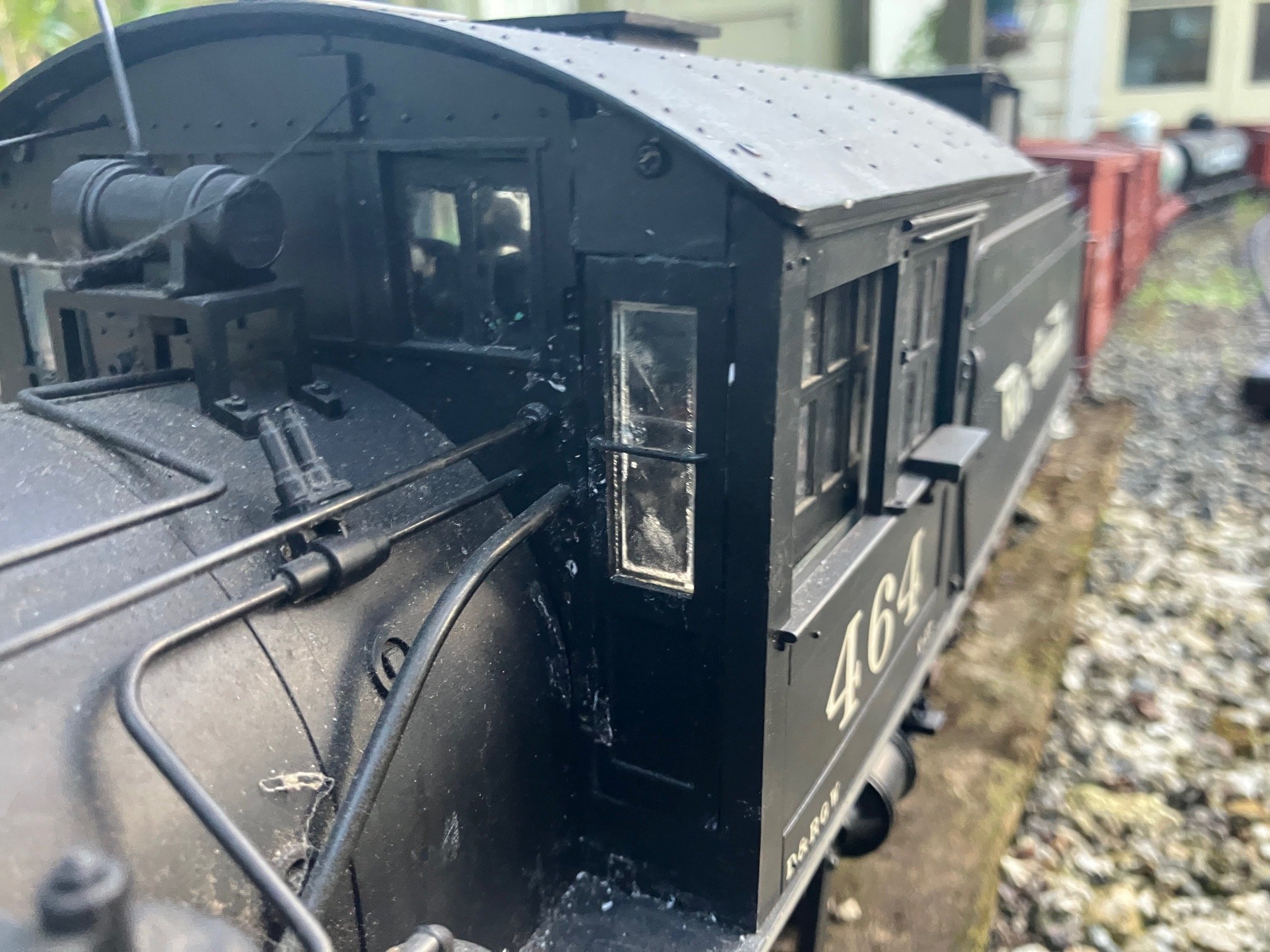
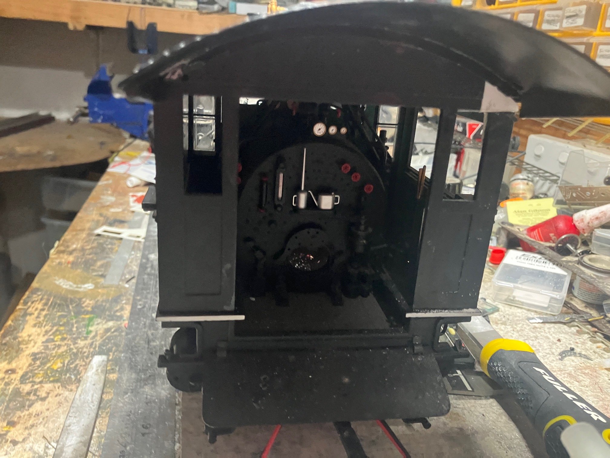
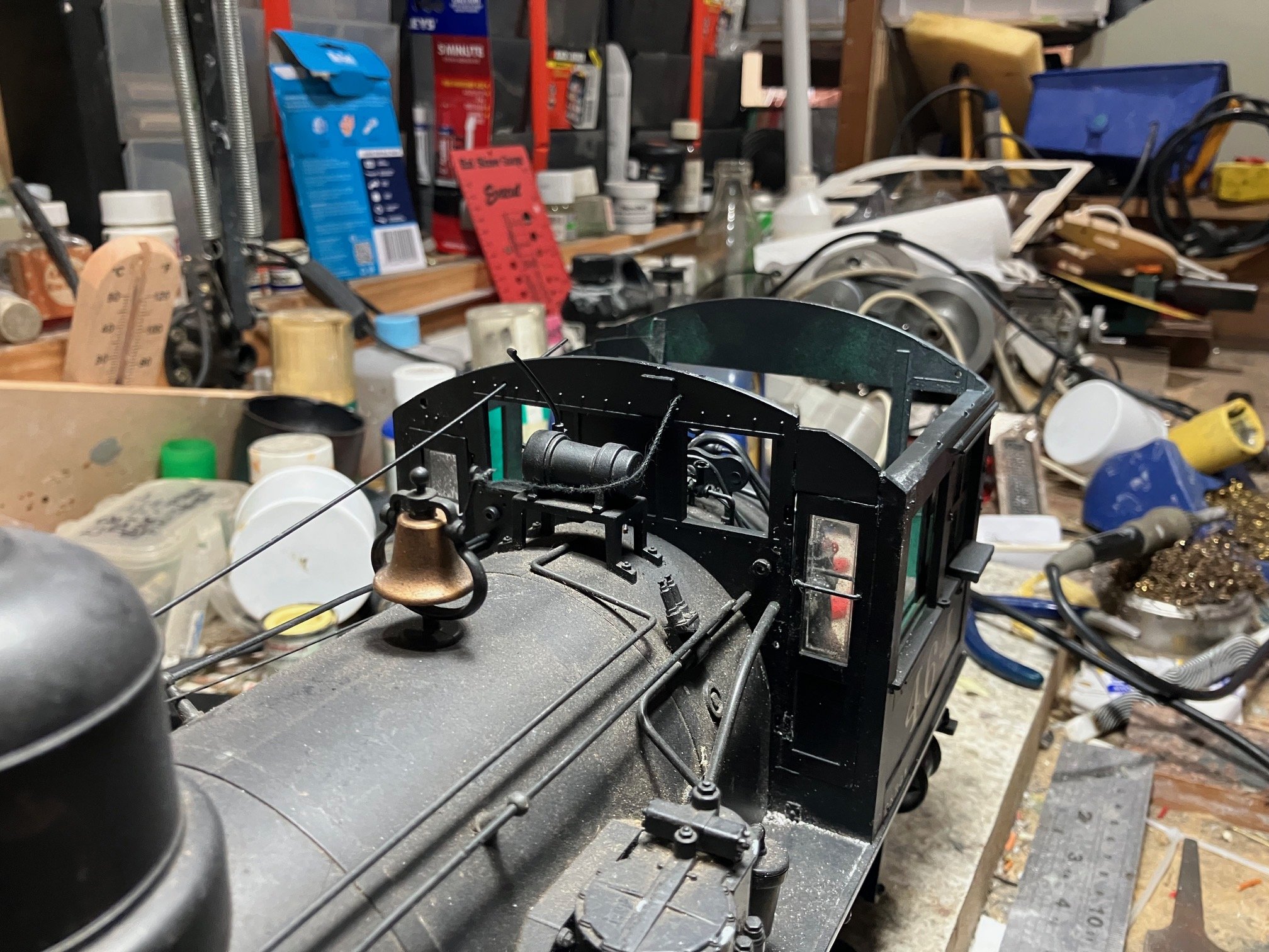
Completed work on # 464s cabs replaced sliding windows front of cab and fixed roof in place with 4 small self tapping screws (slightly different position to originals. Re-charged loco ran several laps of the circuit, no sign of hesitation and easily climbed the 4% grade returning to the staging in the garage. Photo taken around 5:30pm today, Spring officially began on 1st Sept, though emerging signs of Spring since Mid-July. Now to tidy-up clear the workbench to resume work on those J15s!
-
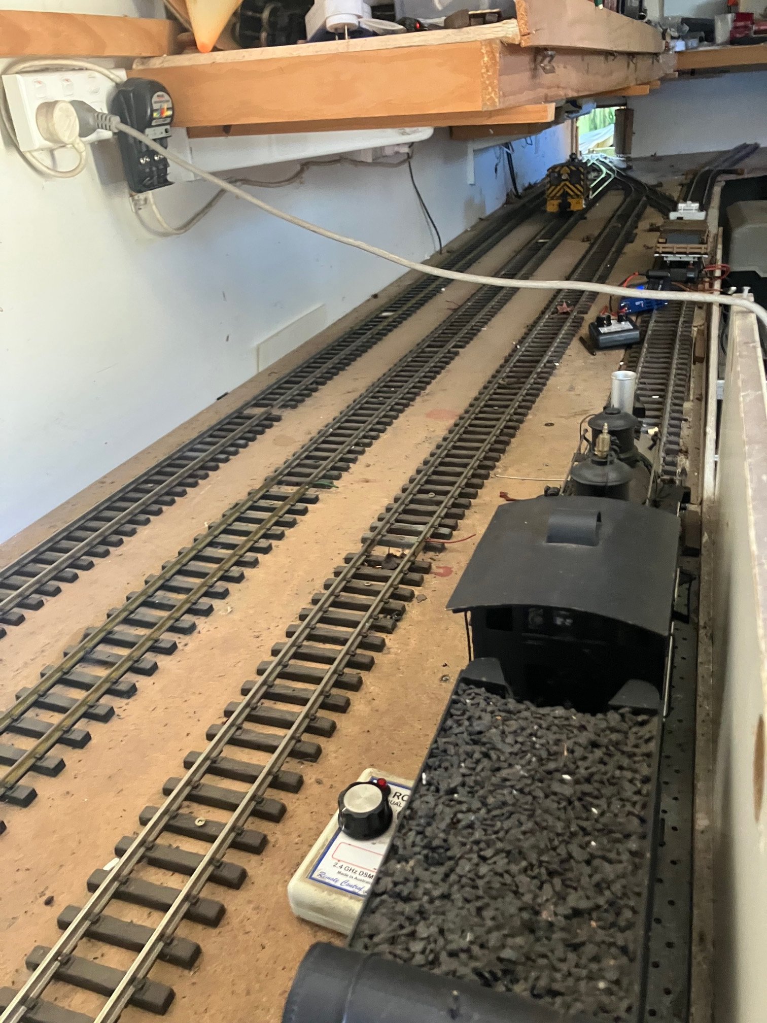
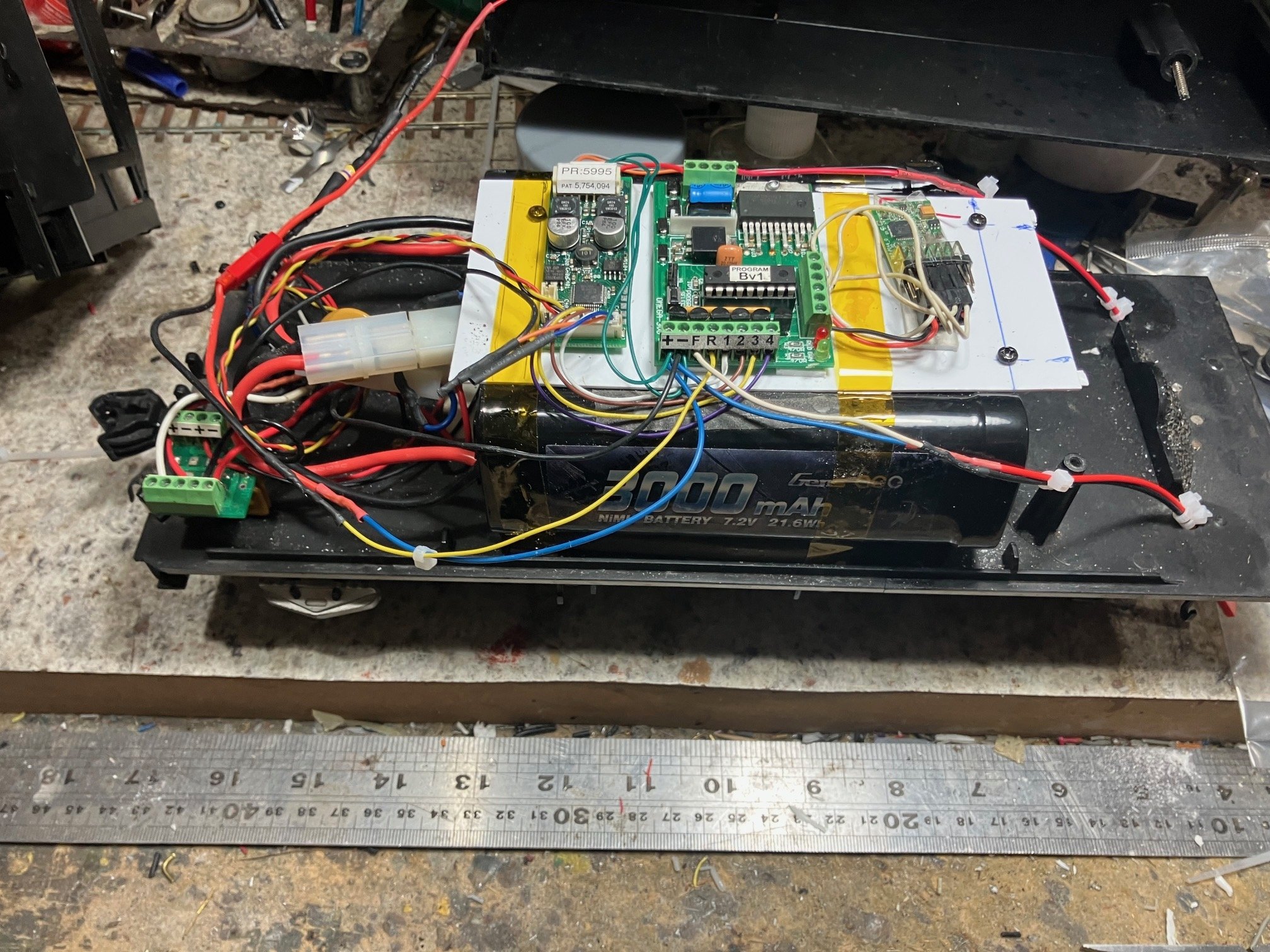
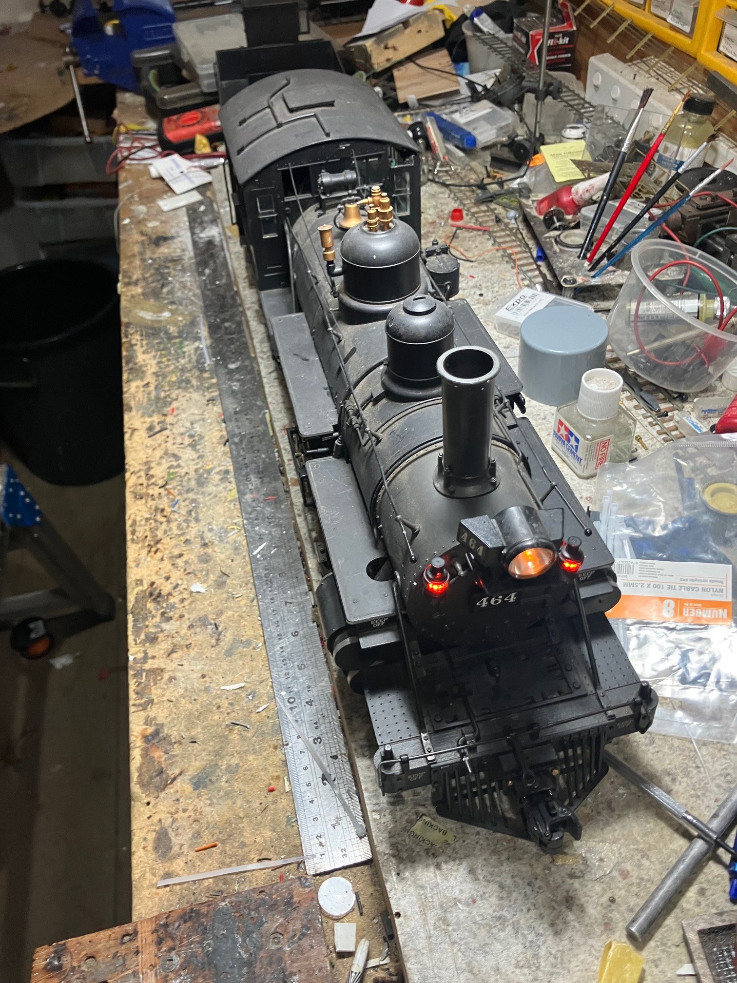
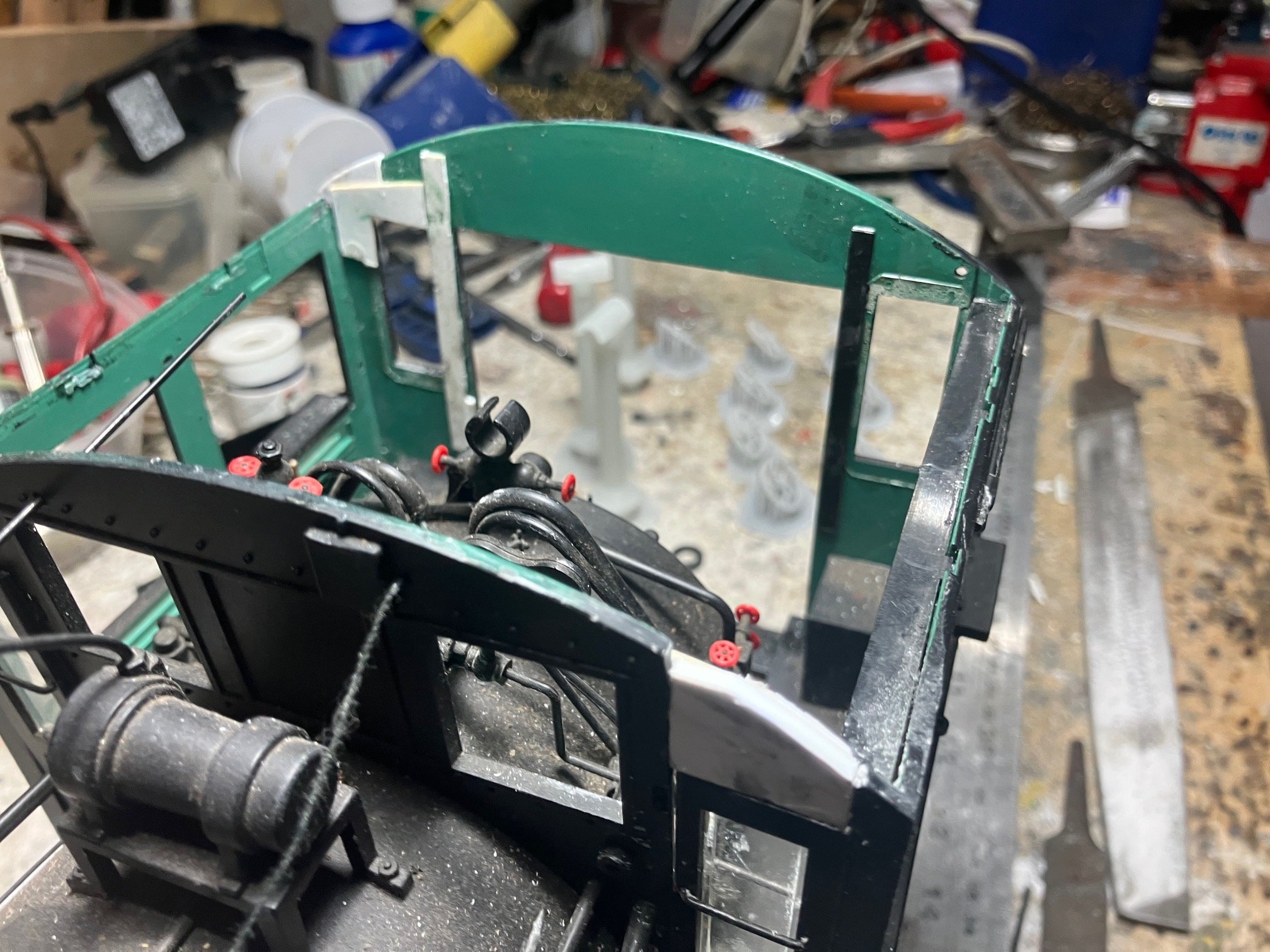
Managed to road test #464 with a train of 5 Stock Cars and a Caboose and its performance was reasonably satisfactory even managed to haul itself and its train up the long 4% grade to the staging without assistance. It looks lncreasingly like the adhesive/masking tape I found rubbing/binding on the motor flywheel had contributed to the locos poor performance and power drain. Simplified tender wiring with Bachmann circuit board/DCC/RC socket removed. Sound, speed controller and RC receiver mounted with double sided foam tape on 40Thou plasticard on mounting posts for Bachmann circuit board. Pair of 3000 NiMh batteries mounted pannier style either side of speaker and mounting posts. Batteries are again seated on double sided foam tape with Kapton tape straps keeping everything in place. The circuit board with the screw terminals on the left is part of an RCS change over switch from run to charge mode. Battery packs are 7.2V packs intended for model RC cars with a Tayima plug interface & heavy gauge wiring! Partially hidden is a (brown) polyswitch (self-resetting fuse) in case of an overcurrent fault. Finally working Head and Classification lights! I decided to carry out some cosmetic repairs while the loco was still on the work bench. The injection moulded plastic cab is now quite brittle approx 18 years since manufacture and sections had broken off in two of the corners where the roof was fixed to the cab with small self tap screws. So repair reinforce the damaged sections with pieces of plasticard. The basic approach was to remove the damaged section of plastic and replace with a section of plasticard of the same or similar thickness, allow the adhesive to harden for several days before forming to the roof profile with a bastard file. (quite a change from woring in the smaller scales. Paint repairs/touch up were by masking around the affected areas and touch up with aerosol etch primer and 'black" (originally a custom mix for wagon/coach roofs) Exposed to the weather and a dusty indoor (workshop) environment, it doesn't take long for my stock to weather! Fortunately the notch in repaired section is not noticeable when the cab roof is fitted, it was the largest piece of plasticard of a suitable thickness I had in stock. Hopefully I'll complete work on the cab next week, and tidy up the bench to resume work on the 4mm J15s I firts started 7-8 years ago.
-
A great "might of been" was the early 1900s proposal of Blacksod Bay as a terminus for Trans-Atlantic liner traffic as part of the "All Red Route" (all British) mail route between the United Kingdom and Canada and ultimately the Far East & Australia using Canadian Pacific railway and steam ship services. Proposals included setting up a new steam-ship company/line to operate between the United Kingdom & Canada and lines linking the Blacksod Bay terminus with the Irish Railway system and apparrently a proposal for a rail ferry between Holyhead and Dublin for trans-Atlantic passengers. https://www.archiseek.com/1915-railway-terminus-blacksod-bay-co-mayo/ Interestingly the Archiseek article writes about Blacksod ousting Liverpool as the departure point for British passenger traffic, but for Scandanavia too! My late father in law's family emigrated from Norway to farm in the US Mid-West during the 1880s, perhaps the British realised that it needed hardy Scandanavians to settle/farm its grain growing provinces. There seems to have been attempts to revive the proposal during the 1920s including re-gauging the C&L as part of a route linking Greenore and Blacksod, the proposal overtaken by World events (WW1 & events in Ireland) and developments in technology (faster ships & aeroplanes! Potentially interesting model if built and Liners continued to call into the 1950s, sleepy "Minories" terminus with sparce local passenger & goods traffic, possibly once-twice weekly boat trains in connection with Trans-Atlantic sailings.
-
The MGWR used similar complex arrangements at several of its major stations (Broadstone, Mullingar, Galway, Sligo) and even double slip connections to goods yards at Edenderry and Kingscourt quiet branch line terminals. Galway station is in a compact urban location hemed in by Lough Atila to the east the connections to the Goods Yard (former Dock Branch) and Loco Depot & Clifden Branch fanning out on either side of the main-line at the station throat. Up to the 2000s the connection from main line to goods yard/loop included a double slip. At Sligo the connections to the loco depot and Quay Branch made in relatively compact location though unsure whether complex trackwork was required on crossover between up & down main line and quay branch. The normal practice a both Galway and Sligo the normal practice during the 70s-2000s era of loco-haulage was for the loco to propel passenger train out past the signal cabin/station throat before running round on the long loop outside the station, before propelling the train back into the station. For many years Sligo continued to operate separate arrival and departure platforms, Galway (& Broadstone) lost their 'arrival platforms" under GSR ownership during the 30s. I guess a Galway or Sligo style run round/shunting movement could be performed by running into the fiddle yard with a suitable view blocker. Minories appears to have been originally designed around the intensive steam hauled suburban operation like the "GER Jazz" services that operated in some of the major UK cities before the days of electrification & unit-based operations. Basically frequent suburban trains arrived and departed behind different locos. A loco from a loco spur or depot would couple up to a train after arrival and work the next departure, the train engine would then take its place at the spur or depot awaiting the next departure. Not unlike the operation of loco hauled services at Heuston in later years where another loco would couple on to the rear of an arriving Intercity service, releasing the train loco after departure to the Valeting plant or a main line departure.
-
The loco spur was a critical part of the orignal Minories (Min-ories) design as the "City" terminus of an intensively worked inner suburban service. A loco from the spur would couple on to the rear of a train following arrival to work the next departure, while the 'train engine" would follow the departing train to take its place in the spur (servicing & watering) before working the next departure, so potentially a lot of loco movement/shunting rather than carriage/non-passenger stock movement, not dis-similar to Heuston 70s-2000s(without the carriage wash movements) Not sure if this type of intensive suburban operation existed in Ireland during the steam era possibly BCDR to Hollywood, Bangor or Comber, DSER/GSR Amiens St/Westland Row-Kingstown short distance workings. I helped operate the late Jim Beale's (MRSI & Marks Models) OO Minories style 70s-90s era BR layout at the Bangor Exhibition 25-30 years ago, we were kept busy keeping things moving using 1st & 2nd Generation DMUs. To add variety the layout included a parcels dock and Class 31 hauled (4 bogie vans (BR PLV?) which required a run-round and shunting movement, tried once during the exhibition before reverting to exclusively DMU operation for the remainder of the exhibition as it brought all other movements to a halt. I guess in a MGWR context a J26 or even a G2 could act as station pilot drawing out the coaches to release the train loco after arrival and making up the departing train including adding vans and non-passenger stock while the train loco is turned and serviced before its next departure. I found from operating my garden railway that there are advantages in operating a leisurly service with 1-2 return services during an operating session. With Sligo there is the added variety of incorporating SLNCR & WLWR workings and incorporating Clifden workings into a layout based on Galway with arriving and departing trains apparrently required to run-round on the Lough Atila Viaduct, Board of Trade banned Clifden trains propelling in and out of the station before opening.
-
The "Is Minories Operationally Satisfying' thread goes into the pioneering O gauge Maybank layout of the 30s thats said to have inspired Cyril Freezers Minories design. https://www.rmweb.co.uk/topic/131100-is-minories-operationally-satisfying/page/8/ Maybank (O gauge) featured a 4 platform main line terminus to fiddle yard (possibly first) with the loco depot located above the fiddle yard( 4 road motorised traverser) with a single line linking the terminus and loco depot. I was lucky enough to see a similar O gauge Milton Keynes club layout at a Home Counties exhibition during the late 80s and fascinated by its realistic operation, unfortunately the layout was dismantled when I joined the club during the early 90s. Interestingly I worked on a construction site in "The Minories" an City of London street during the late 80s, I regularly used LT for my daily commute from Kingsbury to Aldgate. Highling of the day was the evening commute by a direct (limited stop) Metropolitan Line service from one of Aldgate's terminal platforms over the Circle and Metropolitan Lines to Finchely Road before changing to the Jubilee Line for the remainder of my journey home. At the time Aldgate was interesting an island platform through station with two terminal platforms for Metropolitan Line services all beneath and overall roof with good natural lighting at platform level, apparrently buried beneath some office block these days. Going back to a Midland theme Sligo almost fits the Maybank-Minories theme with loco depot separate from passenger station and branch line to Quays, though could always model a version of Galway with loco depot ooof or on scene at Renmore. Main challenge would seem to be fitting the carriage sidings between the arrival and departure platforms characteristic of MGWR principal terminals.
-
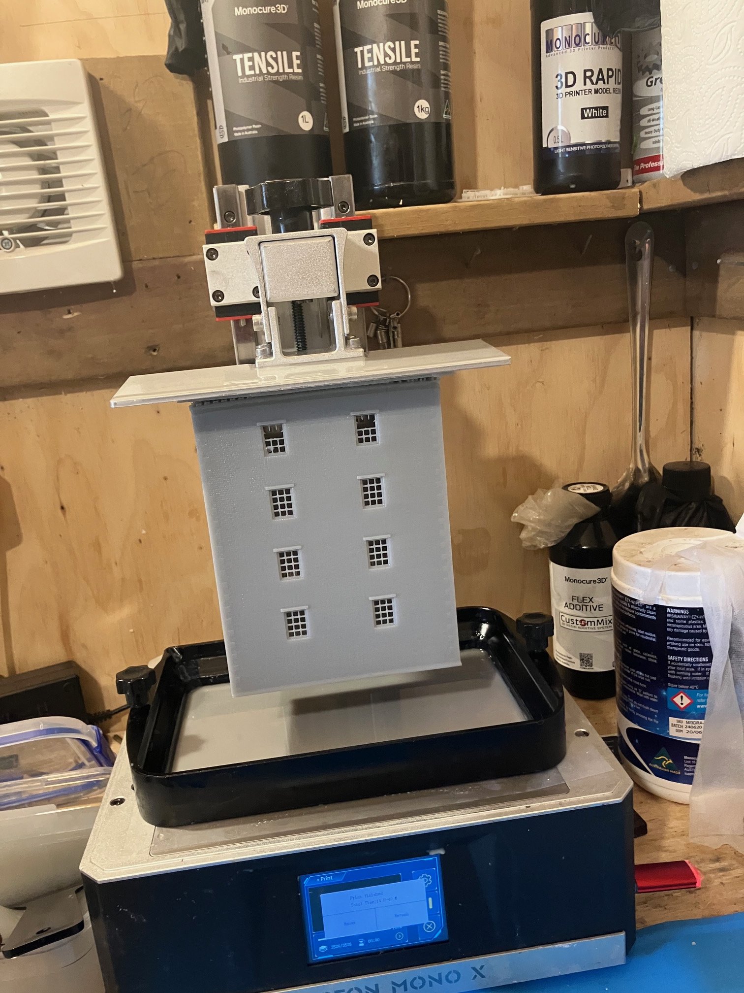
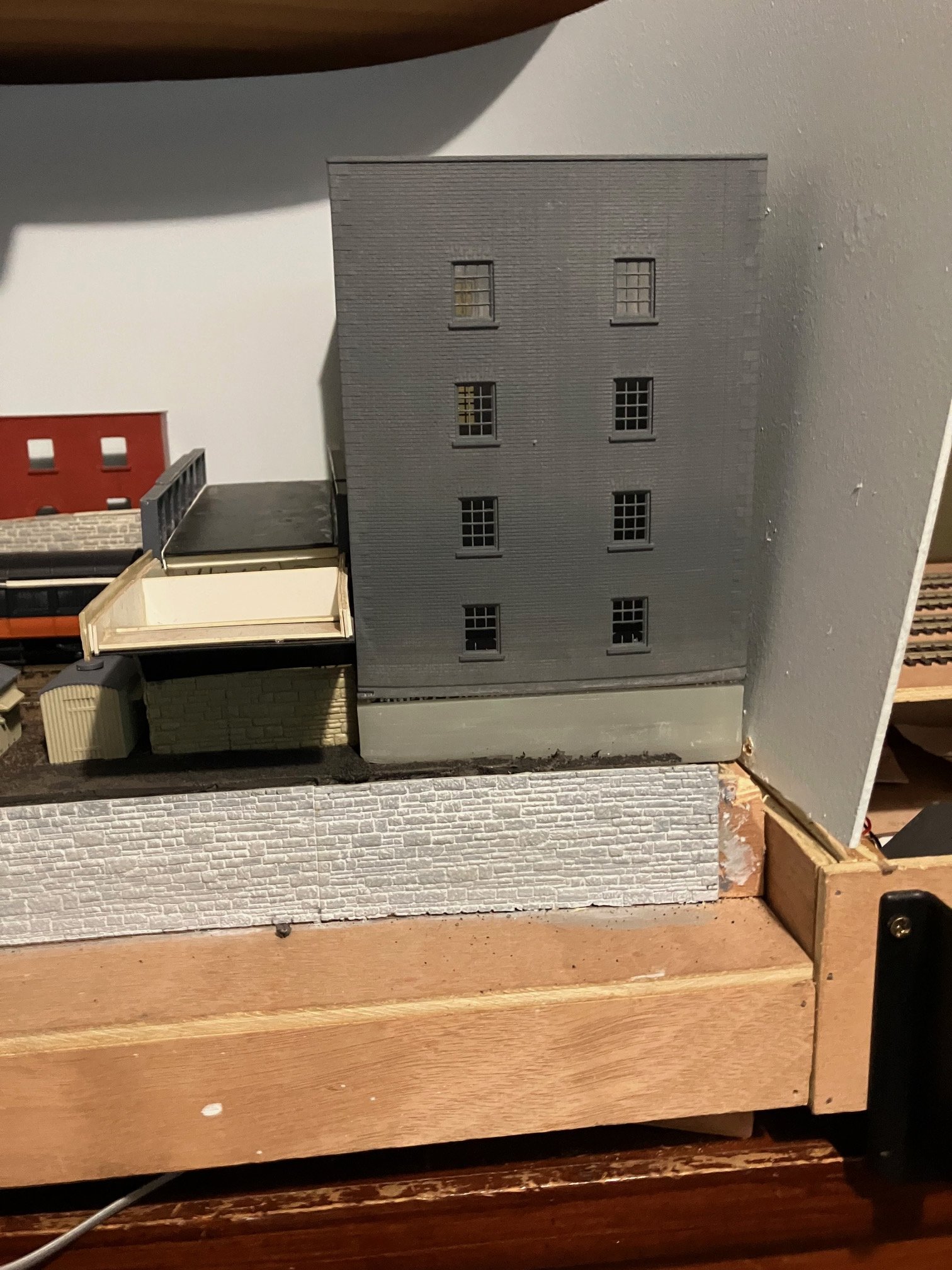
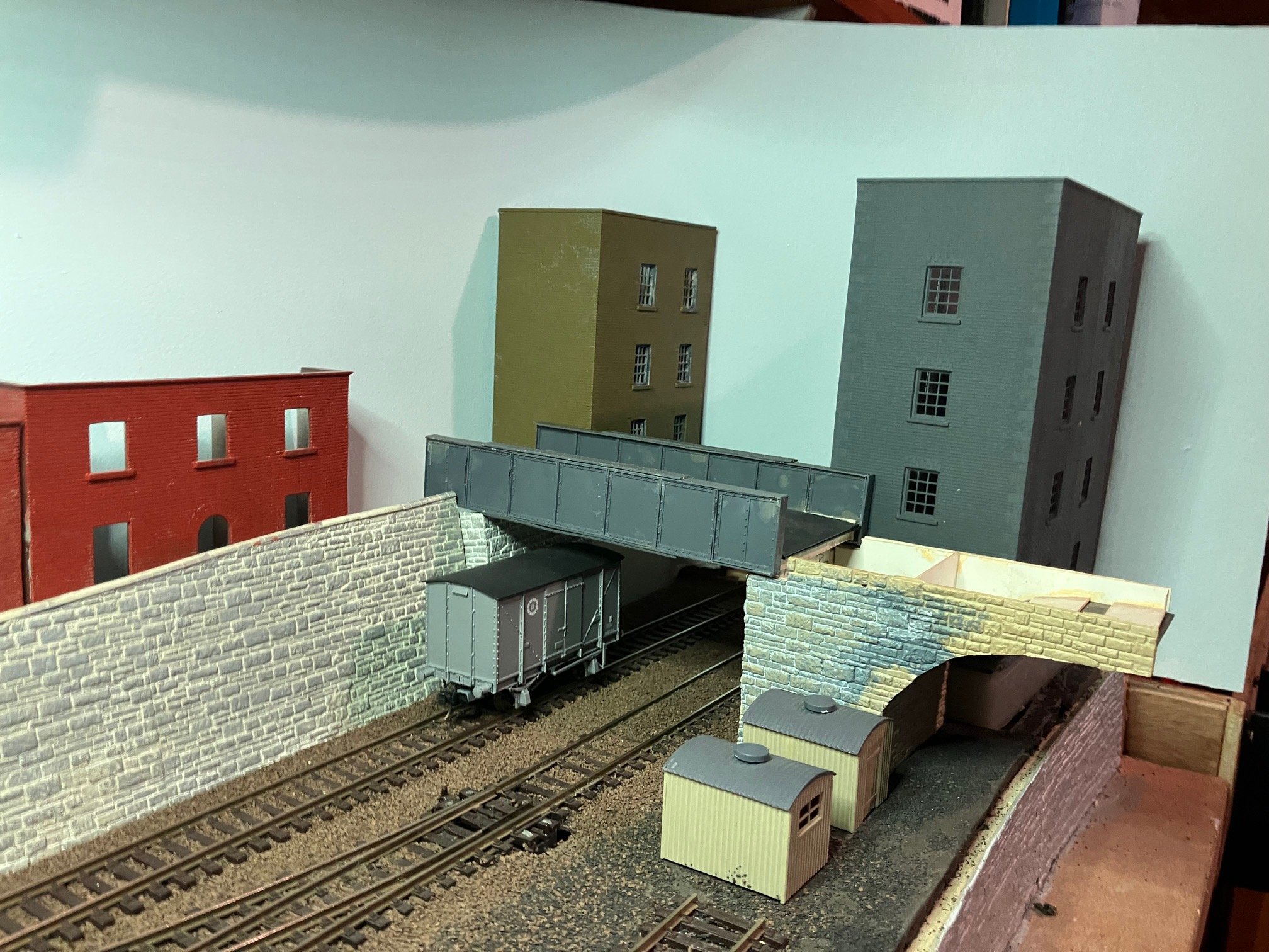
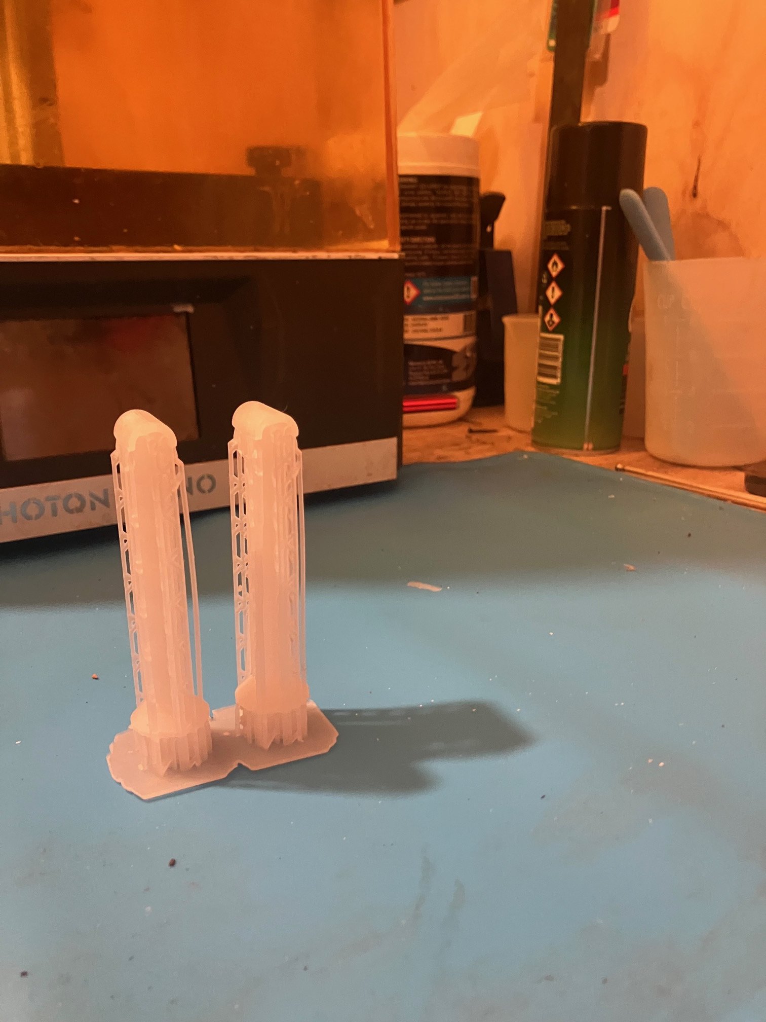
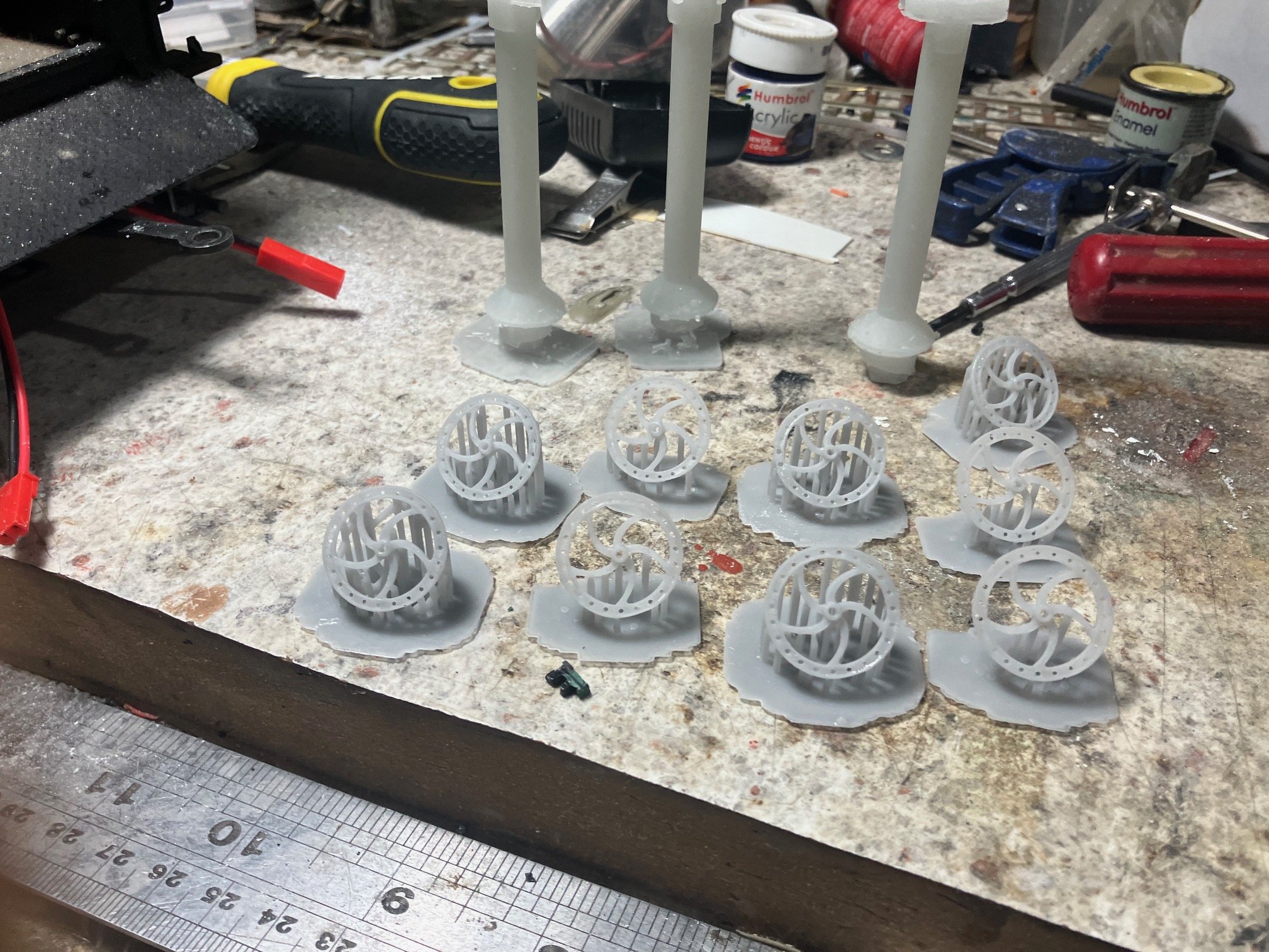
Not much physical modelling since the last post. I overdid things doing some maintenance work on the house and had to rest up for the last couple of weeks. I ended up doing a re-print of the upper levels Tower Building with reduced Lift & Retract speeds, took longer(14½ Hrs) but eliminated the majority of faults with the earlier print. The Tower Building is printed in a Tensile 'engineering resin" having exhausted the local supply of 'eSun' water washable resin I normally use for buildings. One of the challenges with 3D printing is sourcing relevant printing guidelines as resin manufacturers continually upgrade change their products. Although bought in 2025 the manufacturer since upgraded their Tensile and other resins and technical information on the earlier verisons no longer accessible on manufacturers web site. Tower Building after 14½ hrs ready for removal from the build plate and start the washing & curing processes. Some distortion on the initial layers and one row of glazing bars did not print but otherwise good. At this stage I had decided to print the stonework base section as a separate print to the brickwork upper levels The original idea was to print the stonework integral with the base as no of the available stonework sheets are strictly correct for the 'coarsed random rubble' stonework commonly used in Irish industrial and railway buildings. In the end I decided to use Wills 'Coarsed' or possibly "Dressed' stonework to match the material used on other buildings and structures on the layout. I am satisfied with the base print, for the print I trialled Lychee slicing software, in the hope of overcoming some of the print quality issues experienced with the slicing software supplied with the printer in 2021. Printer is incompitable with the current version of Anycubic slicing software. Probabably re-print the base section with the original software using same/similar settings to the upper section of the Tower. Now getting to the stage of finishing the overbridge modelling the roadway and parapets and figuring out how to support the end of the backscene. Turned out that I only have enough etched windows and doors for one house in the terrace, so I'll probabably update the drawing/artwork to complete the entire terrace, etched lintols no longer needed following the shift from conventional to 3D modelling. Digitally (3D) modelling brickwork can be very theraputic almost the current day equivalent of the practice of modelling brick work with individual "punched card" bricks or "computer chads" once poplarised for fince scale modelling. Some Large Scale 1:20.3 Prints! Caboose smoke stacks with supports. These had been a vunerable item with two 'missing in action" on the Garden Railway during the last couple of years, a vertical print in Tensile resin two as direct replacements with one as a spare. Selection of smokestacks with supports removed and handbrake wheels printed at 45° which helps minimise print failure/distortion during printing.
-
Jonathan: You did a very neat clean job in assembling your bogie van, very little clean up required to get to priming stage. Although I have a mini-sandblaster and fibre glass pens, I usually use very fine (200-300 grit) wet and dry to remove severe tarnish, before washing the model using water & detergent (tooth brush can help to remove grime). Dry thoroughly (at least 24hrs) preferably under a dust free cover in a warm (20+c) dry environment before spraying with an etch-primer. I use a rattle can etch-primer from the local motor-factor/auto paint supplier. Although I also have an air-brush I have used aerosols (rattle-cans) custom match/mixed with paint samples/existing models/RAL/BS codes for painting locos & stock. For the past 25 or so years I have been lucky enough to have carried out my spray painting in a workshop and a spray booth, but not a good idea in the home environment.
-
Interesting Chatgpt being great for translating English into Irish and useful for generating text. I suspect that AI is likely to reshape the nature of architectural and engineering design in a similar manner to the development of CAD in the early 60s leading to Autocad becoming an industry standard by the early 80s largely replacing traditional manual draughting. https://www.autodesk.com/design-make/articles/ai-in-architecture. Couple of years ago considered enrolling our 16 year old on a 'Graphic Design" taster with the local college of technology only to discover firms were replacing experienced designers with AI.
-
No 49 unique with side window cab officially withdrawn 1945 seems to have spent her final years in Wexford. Vaguely remember seeing photos of the 47- E3 Class at Wexford, there is a 1933 photo of a newly repainted No49 at Inchacore in GSR Locomotives possiby following an overhaul. Wexford South-Rosslare former GSWR territory, the 0-4-4BT maight have been useful of Wexford-Rosslare locals & possibly Enniscorthy pilot duty & Enniscorthy-Wexford mixed train.
-
British locos and stock that can be disguised as Irish
Mayner replied to Westcorkrailway's topic in Irish Models
A MRSI member Brian Fennel built a MGW 6 wheeler about 25-30 years ago using body using Ratio/Parkside MR clearstory sides on an SSM GSWR 6w chassis for use on the 21mm gauge Loughrea layout. The MR Clearstory sides looked reasonably close to Atock style panneling, though I don't know if Brian got round to infilling/blanking off the toplights and replacing the vent hoods (above the doors). Probabably be simpler quicker to scratchbuild in plasticard. For those thinking of using the Parkside (Ratio) coaches as a 'near enough' Irish coaches AnthonyRailwayB You-Tube videos provide a usefull 'step by step" in assembling these coaches. The GNR bought 20 ex-LNWR coaches of different profiles/styling following WW11 & some older NCC (BNCR) bogie coaches had a similar panneling style to the LNWR -
With the garden railway "operation" tended to be tied in with mowing the lawn/gardening. Running a freight from Placerville/Ridgeway the garage staging/fiddle yard out to Jackson City (through terminus) dropping off/picking up cars en route, loco goes 'on shed" turning/stabling before returning to Placerville/Ridgeway in the evening after tea time. Real busy day might run a Stock Special to one of the smaller stations/yards. But not a lot of action in recent years, lot of the effort goes into just about keeping the line in locos just about servicable. Saw-by crossings. Auto-Train Original 'Double Saw-By' video reminded me about a story in John Thomas "West Highland Railway book about the crossing of a long double headed passenger train using a single saw-by technique at one of the intermediate stations. Don't know if similar manouvers were ever performed/necessary in Ireland, crossing loops on single line sections often incorporated a (long) layby/siding extension allowing long goods trains (often 50-60 loose coupled) to be crossed that were longer than the loop. The layby sidings were also used to stable a goods/freight clear off the main line and loop or allow three or more trains to cross. Maynooth was a good example, during the early 80s I once saw the down (Dublin-Sligo) Liner behind a 001 Class shunted/propelled to the long layby siding at the Leixlip end of the station to allow the Down Connolly-Galway Night Mail and the up evening Sligo-Connolly Passenger to pass. On a Saturday morning almost 20 years later I watched the Layby at the Enfield end of the loop being used to stable a laden North Wall-Sligo ESSO oil train while awaiting a 'main line" crew. The oil train had been moved to Maynooth (possibly North Wall shunt crew) to clear space at the North Wall, the train later continuing to Sligo possibly on Monday! During the same era I once saw a Down Sligo Liner stabled during the weekend at the Down Galway platform Mullingar.