
Mayner
-
Posts
4,734 -
Joined
-
Last visited
-
Days Won
118
Content Type
Profiles
Forums
Resource Library
Events
Gallery
Blogs
Store
Community Map
Posts posted by Mayner
-
-
Fairly distant recording but interesting comparison between 001s and the small GMs
There seems to be relatively little recorded on the 001 class and even less on the B201s which always seemed to be louder accelerating than other locos.
-
Hopefully coming to a shop near us in the not too distant future!! Thanks for the comments
The whitemetal B121 was probably one of the best of the MIR loco kits.
-
The ESU sound files for the EMD 12-645 non-turbo 74443 is probably the closest you will get to an 001 Class. The As were rebuilt with a 12 cylinder non-turbo engine similar to that used in EMD American Switchers and some export diesels. The tone of the engine is noticeably different to the 16-645 engines used in American road locos.
Its good to see a model A Class with correct unequal wheelbase trucks. I assembled a whitemetal MIR A Class about 20 years ago using the trucks and drive from an SD9 I did not realise that the SD40 trucks were closer.
-
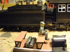
Bit of light relief after the fine detail work on the horsebox.

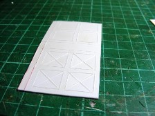
Marking and cutting out the cab windows from .040" plasticard for the large scale 2-8-0
One set cut another three to go. The outline is scored half way through on one side, the diagonals half way through from both sides, than snap out the triangular shaped pieces of waste.
Windows cut minimal cleaning up needed.
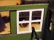
Window frame fits into rebate in cab side built up from 3 layers of plasticard.
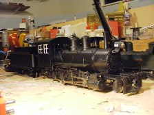
The 2-8-0 should be back in service later this month once the radio control gear arrives. The loco has been out of service since 2011 after an apparent overload and decoder shut down. I could not find any problem with the motor or the loco wiring at the time, but found a dead short on the motor when I was re-assembling the loco last week, luckily enough I had a spare motor in stock, also replaced driving axle. The loco is in an automotive satin black, but I found an unopened bottles of Floquil Grimy Black, Weathered Black, Gunmetal & Graphite which should result in a more interesting finish.
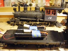
On-board battery power a pair of 7.2v rc-car batteries. Rc-receiver and control gear will be mounted in the tender, misht even fit in a sound unit. Loco in background was an earlier conversion finished in Floquil Weathered Black.
2 AAA batteries on board power Model T Railcar
Nearly finished and detailed, have to find the headlamp lenses and missing door handle.
DCC demonstration
-
The SLNCR probably would have got by without spending too much money on the track, a 2-6-2+2-6-2 Garratt would probably have been easier on the track than the indigenous 0-6-4Ts and GNR 0-6-0s. Garratts were used successfully to haul heavy ore and freight trains in Tasmania in conditions similar to the SLNCR high rainfall, sharp curves, steep grades light grades indifferent track maintenance.
I think the main problem would have been handling longer heavier trains and finding the money to pay for the locos. The SLNCR did not have the money to pay for Lough Erne & Lough Melvin when they were completed in 1949 and Stormont underwriting the hire purchase agreement for the two locos in 1951. The SLNCR mainly benefited the ports of Belfast & Derry and Merrion Street was unlikely to be willing to subsidise the SLNCR to compete with CIE for Sligo-Dublin freight traffic
There was also the little matter of whether the boiler unit or power bogies would fit in the erecting shop at Dundalk Works
-
The Garratt is mentioned in Neil Spinks' SLNCR book. The 1920s proposal may have been to replace the two Avonside 0-6-2T locos withdrawn around the same time. The SLNCR was skint at the time and bought a pair of elderly GNR 4-4-0s which did not last very long and were in turn replaced with ex GNR 0-6-0s which had worn out by the time the SLNCR went shopping for new locos in the late 1940s.
A Garratt appears to have been again considered but Lough Erne & Lough Melvin ordered instead.
A Garratt would have appeared attractive in reducing operating costs and train milage, possibly with a single daily goods replacing the two scheduled goods/mixed workings. At least a second Garratt would have been needed as a standby to cover maintenance. Its hard to imagine how a Garratt would have performed or how the SLNCR could have safely handled heavier longer loose coupled trains over those grades and curves.
-
John,
What is it that makes modern track more rigid? Deeper ballasting? And that would have been done as locos became heavier?
Presumably modern locos would be more track friendly if the traction motors were sprung?
Its a combination of the heavier rail and deeper ballast that makes modern track more rigid. The move to more rigid track and stock with automotive style springing was driven more to reduce track maintenance costs than by heavier locos with higher axle loads.
The choice between axle mounted and frame mounted traction motors with carden shaft drive to the axles is probably a trade off between increased track Vs rolling stock maintenance costs.
Internationally most diesel electrics & straight electrics tend to have un-sprung traction motors, the exceptions like the British IC125 power cars & ECML Class 91 electrics were designed for continuous 100mph + running.
Once the track is adequately maintained running heavy locos with axle mounted traction motors is not a problem, but even where light locos were used poor track maintenance is a recepie for disaster.
-
Mayner, I;ve never seen the Blue Point Switches before. They look interesting, whats their longevity like, is the throw adjustable?
I have used them 3-4 years without any problems, the throw is adjustable the overall design is similar to the Tortoise switch machine without an electric motor.
The wiring is similar in principal to that described by DuVaren with the one pole of the Blue Point DPDT rather than a relay used to switch power from the main line to the yard controller.
-
How do you know all these things?, thanks John your imputes are always a lesson in the learning.
Mispent years volunteering in a civil engineering gang on a narrow gauge heritage railway in the UK and still having the curiosity of a little boy who simply has to know why?
Got to know a lot of professional & volunteer railway people, got my hands dirty, enjoyed myself and drank a lot of beer.
-
While modern diesel hydraulic railcars like the Rotems and CAFs are easy on the track, most diesel electric locos and railcars are harder on the track than a large steam loco as the traction motors are unsprung.
With a 2 cylinder steam loco at high speed and rigid track there is a risk of the loco bouncing itself off the track as well as damage to the loco.
Most of the track and infratructure problems on IE in the 1990s and NIR arose from a combination of running diesel electric locos and railcars at high speed on inadequately maintained track.
I suppose packing and lifting and ballast cleaning is a form of preventative maintenance to prevent this sort of problem developing
Ballast cleaning may be the only option where it is not feasible to raise the level of the track due to restricted clearance or at station platforms. Ballast cleaning has the advantage that it can be carried out between trains, important on a freight railway where customers would not tolerate disruption to traffic.
-
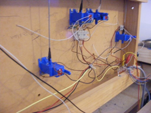
I have an end to end layout with a station with a small yard and loco depot.
Two locos can run at a time one on the main line the other in the yard.
Two hand end controllers (one Gaugemaster one home made) one to control the main line, the other to control the yard and loco depot.
Blue Point Switch Machines http://www.micromark.com/blue-point-switch-machine-turnout-controller-10-pack,8537.html to control points. I use the Blue Point toggle switch rather than section switches to switch control from the yard to the main line controller. This allows trains to run from the main line to or from the yard on the one controller.
The loco yard is divided into sections controlled by toggle switches mounted on the layout fascia, this allows a loco to be parked in the engine shed or the turntable track while the yard controller is in use.
-
So is ballast cleaning a modern exercise, insofar as these machines did not exist in the days of steam? I would think there would have been a lot more ash and debris to settle on the track.
They have been about from the 1940s and in widespread use in Ireland and the UK from the 1960s. The modern high output machines with self loading/unloading ballast/spoil wagons are relatively recent development to increase the amount of work that can be completed within a possession and reduce the need to run separate spoil and ballast trains as part of the ballast cleaning operation.
The need for ballast cleaning is driven more by the grinding down of ballast and concrete sleepers from heavy traffic than from debris falling on the track. Coal ash is quite free draining and used for track ballast and strengthening track foundations & embankments.
Traditionally engineers preferred to add more ballast & "lift and pack" track in preference to ballast cleaning which can sometimes damage track foundations by breaking the crust of compacted fill underneath the ballast. The only cure when this happens is to close the line and re-build from the formation up.
-
Are the Park Royal underframes meant to be of the same sort of, "triangular," idea as the 20t chassis?
Most of the coaches built from the Mid-1950s to Bulleid's departure including some MK2 Bredins, all the Park Royals & Laminates had triangulated underframes,
The idea seems to have been dropped after Bulleid's departure wagons/coaches built from the 60s onwards had conventional underframes.
The solebars curve inwards in the area around the bogie pivots.
David Malone a pioneering 21mm S4 modeller has built a "hooded van" with a representation of a triangulated underframe and full springing
Hooded Van with Bulleid underframe photo © David Malone
-
Richrua. The SSM GNR SG 0-6-0 or possibly the Bandon Tank would be a better option than the J15 for a 1st etched brass loco kit. The SG is easier to build for a less experienced builder than the J15, the combination of flat running plate, slot & tab assembly and bolt together sub-assemblies simplify assembly. Being a larger loco there is room for a decent size motor in the firebox which can be a struggle with the J15
DLT RM Web thread on building Southern locos contains pretty good advice on building etched and whitemetal kits http://www.rmweb.co.uk/community/index.php?/topic/2359-dlts-sr-locos-a-black-motor-for-torrington/page-24
DCC wise it would be best to try and fit a decoder in the tender or tank loco bunker rather than in the boiler as the boiler needs to be filled with weight if the loco is to pull a reasonable load.
Decoder wise a 1 amp N or small HO Decoder like the Lenz Silver Mini+ or Digitrax DN136D will do the job. Lenz decoders are very good, Digitrax have the advantage of being wrapped in insulation so they are unlikely to short against anything. If there is space in the tender a TCS "Keep Alive" or Lenz UPS decoder would greatly assist reliable running over coming issues with power pick up/dirty wheels.
Reliable power pick up is important with kit built locos, programming speed steps with kit built locos is not really an issue generally you pick a motor and gearbox ratio to give a realistic low top speed, generally 80:1 or 50:1 with a goods loco.
-
Model Hump Yard seems to work reliably
Gravity shunting where grades were used to assist sorting wagons was quite common in loose coupled days. There is footage of gravity shunting at Sligo Quay in Markle Associates Irish Railway Archive series.
https://www.youtube.com/watch?v=oRYOlkETWkw
Watched OBB sorting containers wagons and Ammonia tank wagons by gravity in Krems about to years ago. A train from the local industries was held on a headshunt outside of the station and wagons released to run down the grade into the yard.
-
Narrow gauge version of ETM 567 similar machine to the IE Ballast Cleaner in operation in New Zealand.
-
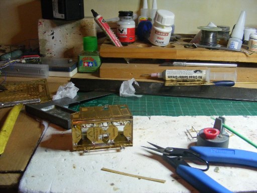
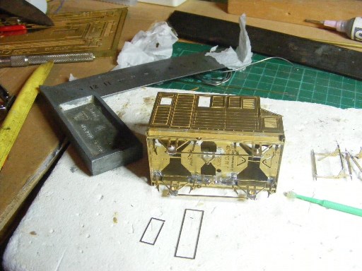
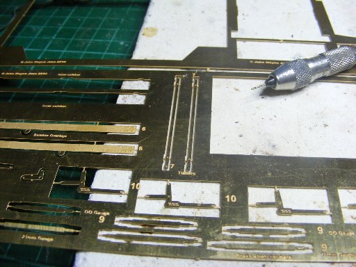
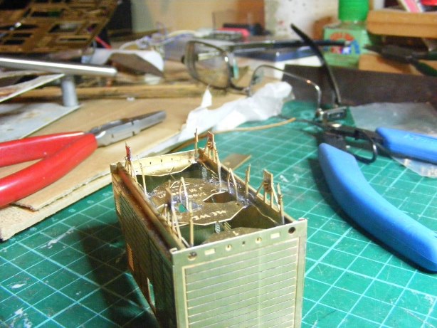
Episode 4 Detail
I prefer solder to cyanoacrylate when working with sheet metal, I usually make a hell of a mess and the stuff usually goes off in the bottle with our humid Waikato weather.
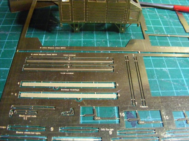
Solebar overlays
These are simply glued or soldered to the sole bars. The knobbly bits are used to support the handbrake shaft and fit at the end closest to the V hangers.
Glue applicator and Xurco tab cutter
All that's needed is a bottle of Red Wine or 10 Year old malt.
I used a Microbrush applicator but the business end quickly got clogged up with half cured CA. Not sure if it would be a good idea to try and keep the applicator clean as you go with MEK or acetone.
Cover slips
The bodywork of MGWR non-passenger coaching stock is quite distinctive with a wagon rather than coaching stock style construction, with cover strips protecting the joints between the body framing and planked body panels.
The raised cover strips are applied separately as its not feasible to represent this type of 3 layer construction with normal engraving technology.
Horse Box door strapping
The doors strapping is designed with a jig to help keep everything in alignment while gluing or soldering in position.
The raised detail is designed to locate in place over half etched channels and lines.
Body with strapping and cover slips fitted
The tabs joining the strapping to the jig can be cut off with a fine nips or a sharp knife. Roof still to be fitted to the dog box section
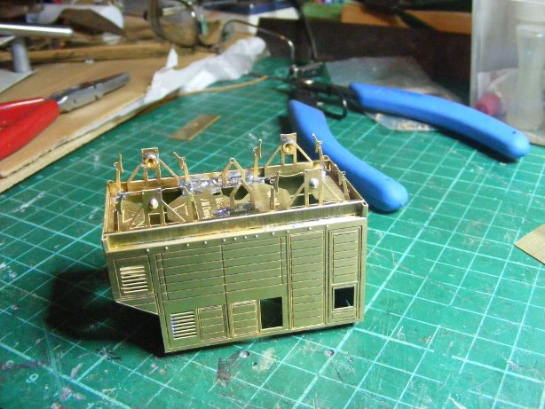
Sheetmetal work more or less complete one side
-
 1
1
-
-
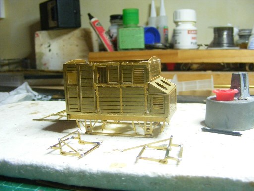
MGWR Horsebox Episode 3 the Soldering Iron Strikes Back
Thanks for the comments Patrick, Kieran and Nelson. The design is nearly de-bugged nearly 12 months after preparing the initial design, its a slow process though I am a little steadier with a CAD programme than a craft knife or piercing saw.
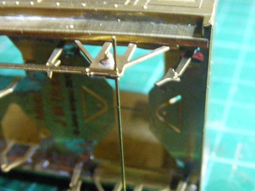
Now for the really fiddly stuff.
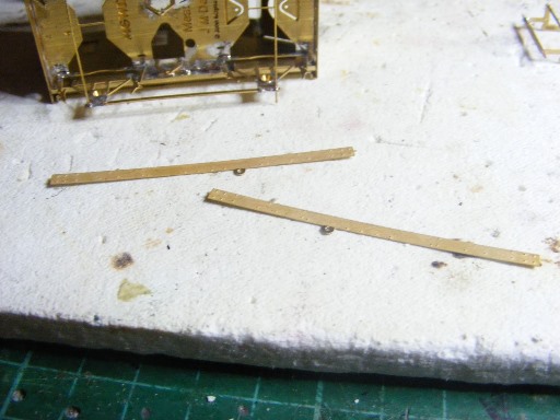
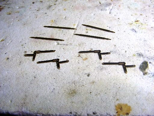
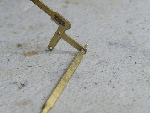
Tie Bars
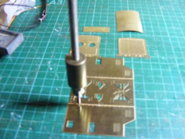
Although the wheelbase was quite short 9' the MGWR used tie bars between the W irons to stiffen the underframe. One of the challenges in designing etched kits is ensuring thin components are not etched away and that holes are not too large or too small. I drilled out the outer holes in the W Irons and tie bars 0.5mm with a drill held in a pin vice. I use titanium coated drill bits for this type of work as they and survive longer than conventional HSS bits.
Fitting the tie bar
I used 0.45mm brass wire as pins threaded through the holes in the axleguards to hold the tie bars in position while soldering.
Plenty of flux and very little solder on the soldering iron tip.
Tie bars fixed in position starting to look like an underframe
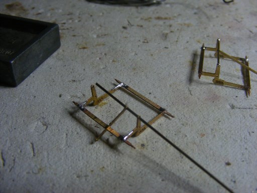
The really-really fiddly stuff brake yokes and pull rods
Probably best left out for a layout model.
I am lucky enough to have a general arrangement drawing for the MGWR meat van which has a similar design of underframe.
The stretcher bars are provided for OO or 21mm gauge and the assembly designed to be removable in order to paint the underframe and fit the wheels.
Yoke and stretcher bars
After a false start with 0.7mm brass wire as stretchers (I could not remove the gear to paint the model after fitting the wheels) I re-designed stretcher bars are designed to slot into the yokes.
Assembled brake yoke stretcher assembly ready for soldering
The white slab is a heat resistant ceramic soldering mat available from Microlux in the USA. The material is soft enough to take a pin or the end of a stretcher bar.
Nearly there assembled yokes with 0.7mm brass wire stretcher bar and pull rods attached
The 0.7 wire is soldered to the yokes the actual pull rods will be secured in position during final assembly.
Next episode Detailing
-
1
-
-
Junction Mad
Calling on arms on the CIE system were re-designated "Loop Homes" following the Manulla collision in the early 1960s.
My understanding is a loop home was intended to allow a train to enter a loop without stopping at the home signal, while with a calling on arm the train was required to stop at the home signal before the calling on arm could be lowered.
The change in designation may also have been tied up with the conversion of crossing places on several lines from conventional Up & Down to bi-directional working in a similar manner to the ex-MGWR main line with a main running road and a loop.
The RAIU a reliable source of information on CIE signalling practice and an insight on what sometimes happened in practice. http://www.raiu.ie/publications/ The report on the 1979 Arklow & Rosslare Strand collision reports make interesting contrast between custom and practice and regulation.
The report into the 1955 Cahir beet train derailment is particularly interesting the station was signalled for traditional up and down working with left hand running through the platform roads rather than reversible working.
The road was set for the ill fated Up beet train to run onto the Down platform road and through the stoppers into the river, as the Down Mail was blocking the up platform road taking water from the column at the Limerick end of the Station
-
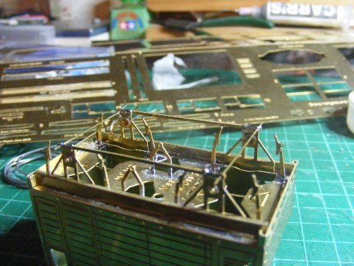
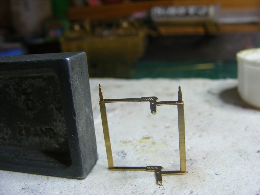
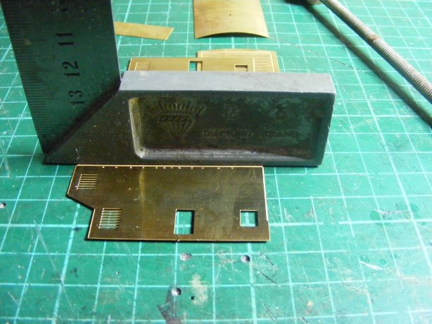
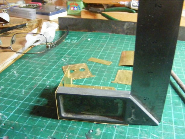
Underframe
The axleguards and brake V hangers are designed to fold up from the floor.
The model can also be assembled with a compensated chassis on the 3 legged stool principal with a set of rocking w irons at one end.
Axleguards folded down I reinforced the w irons with a fillet of solder along the half etched lines.
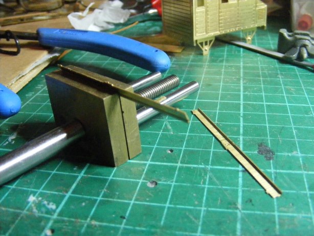
Solebars & overlays
Probably the trickiest part of the assembly the solebars require to be bended to an L profile before being fixed in place.
Forming the solebars
Gently does it!
While a number of companies produce bending tools for etched parts, I have found an engineers square and a small vice with smooth jaws to be the most effective.
I basically clamp the work piece in the jaws of the vice and gradually make the fold using the square or a piece of hardwood stripwood.
Inner solebars soldered in place.
-
1
-
-
Incredible.
What strikes me the most about this is that there is NOTHING that gives this away as a scratch built model!
Until fairly recently high quality scratch built models were often to a higher standard than ready to run models or kits. Richie appears to have mastered the art of building highly detailed models in plasticard, and combined it with subtle choice of colours/weathering.
The level of detail such as brake rigging, highly detailed spring dampers and pipework are usually only found on a high end rtr model or a loco commissioned from a professional model maker.
-
Claremorris was probably the last major mechanical re-signalling scheme carried out by the GSR when the new Central Cabin was opened in the 1940s. The Central cabin replaced the East & West Junction Cabins (or was it North & South), the Ballinrobe Branch Cabin and Yard Ground Frame.
Further alterations were carried out in the 1950s when the loco shed between the down mainline and Ballinrobe branch platforms was demolished and the loco shed road extended to connect with the Tuam Line. This allowed trains to or from the Tuam direction to run into the new Platform 3 while the two Mayo Line platforms were occupied.
The early 50s alterations appear to have used up all the spare levers in the frame resulting in the use of 'economical" point locks on the crossovers opposite the signal cabin and the paired arrangements for operating some of the ground signals.
The signals marked AR were most likely fitted with a repeater to indicate whether the signal lamp was working or not. The signals marked AR controlled exit and entry from the single line sections and it would have been difficult if not impossible for the signalman to observe the state of the lamps from the cabin, given the considerable distance of the signals from the cabin and the way the main line curves away at the East & West ends of the layout.
Up to the Manulla collision in the early 1960s "calling-on" arms were fitted to home signals (mother and child signal) to control movements into a station when the Main Line into the next section was blocked and the Home signal at danger. If the station was blocked the (mother) signal was held at danger and the calling on arm (child signal) only lowered when an approaching train came to a complete stop.
An AEC railcar set was blocked outside of Manulla as a C Class shunted the Night Mail. The signal man forgot to return the "calling on arm" to danger after a shut, seeing the calling-on arm in the off position the driver of the passenger ran into the loop and collided with the mail.
The rule book was re-written after the accident and the 'calling on arms" on CIE re-designated "loop homes", the home signal reading to the main-line. This was ok at stations where bracket signals were at equal height but could be confusing to a driver if the loop was on the right hand side of the running line
-
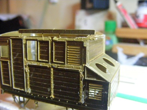
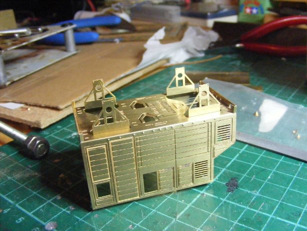
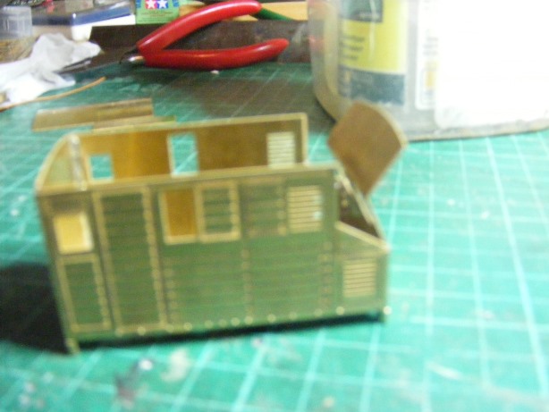
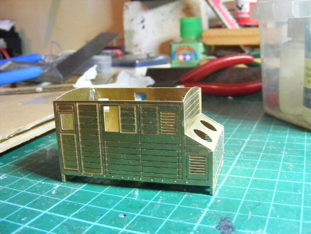
I finally got around to a test build of the revised MGWR Horsebox. The ammendments were mainly to simplify the assembly of the brake gear and beef up the strapping detail on the horsebox doors so that it was not completely etched away in the engraving process.
Main body/chassis components
I was always fascinated by some of the early etched kits that were supposed to fold up from one piece of brass, something that did not really work with single sided engraving.
First task to emboss the boltheads at floor level. I use a riveting tool otherwise a centre punch or scriber will do the job.
Second task fold up the sides using an engineers square to make sure it folds along the line and the floor stays flat.
Check that the fold is at 90
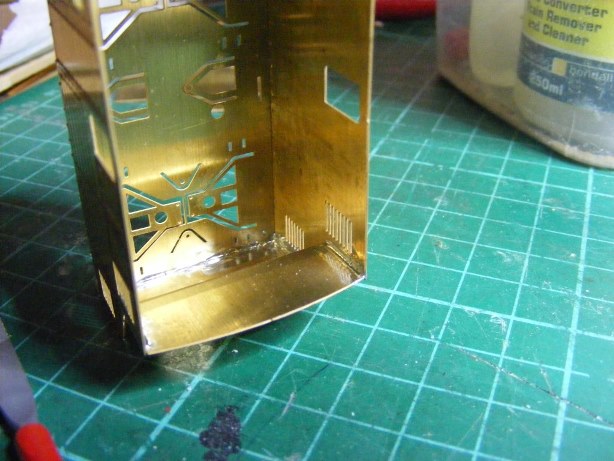
Fold up the headstocks on the ends
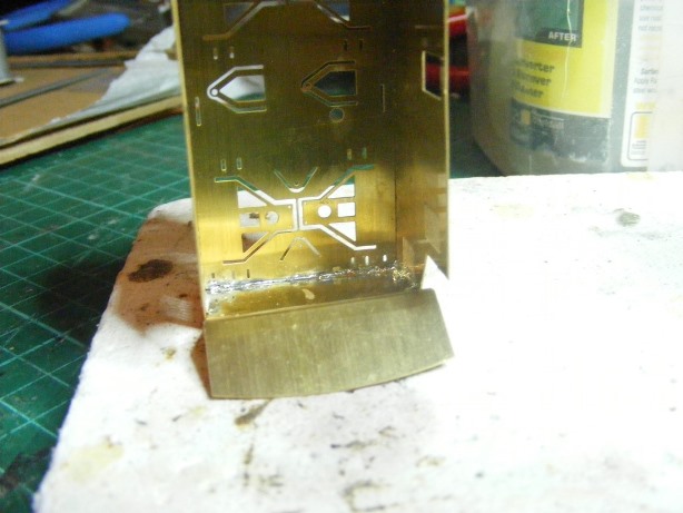
Step Four fit the ends in place between the sides and solder in position
The ends locate into a half etched rebate in the sides, its simplest to solder the bottom section of the bonnet (dog box) end in place before bending the end to shape.
View of soldered joints
I generally use Carrs 145 (detailing solder) or 179 (sheet metal) solder with Carrs Red Label flux. For these joints I used a 50watt temperature controlled iron and 179 solder. The 50watt iron has enough reserve of heat to form a neat filleted joint.
Soldering completed at the dog box end.
Approx. 45 minutes work, horse box body assembled
Next episode will cover chassis assembly
-
1
-
-
From what I've heard from the "Heuston Driver", the problem is with the chinese not willing to communicate/respond. Pretty hard to issue a press release if the man himself is still in the dark.
Anyhoo, they are great coaches with the painting of the central band done by a sloppy operator. It's very fixable. As for the colour not being tan enough, well that's up to preference/memory and nostalgia. Also easily fixable, but i agree - shelling out further wonga after the initial purchase is not ideal.
Chinese like the Irish business men or politicians do not like to admit they cocked up. Asian culture is all about saving face or preserving mana.
Things are usually sorted out by offering the client a discount on the next order or offering a free replacement like in the case of the 1st batch of Heljan Clayton diesel chassis or Bachmann lifetime warranty.
Kiwirail had numerous problems with its Chinese built diesel locos but CNR continue to honour their warranty commitments.
MM was probably required to pay in advance before the manufacturer ran the production version.


.jpg.a06b2e1315f14ec89a6e8ab5716f585d.jpg)

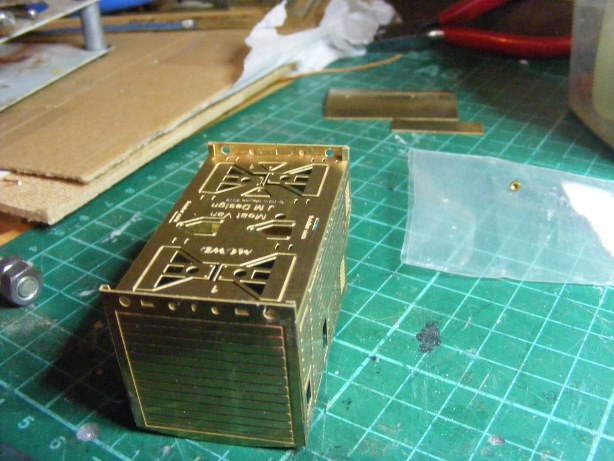


Silverfox D Class Shunter
in News
Posted
The D301 Class seem to have been pretty camera shy in the 1960s possibly because they were doing very little work. According to the ITG website two were out of service by 1960 and never ran again, the last had stopped work by 1970.
An E401 or E421would have been a much better choice for a shunter though its difficult to gauge if there is sufficient demand out there to justify commissioning a decent rtr model, so a repainted 08 is a safer commercial option