eugenepfox
-
Posts
11 -
Joined
-
Last visited
Content Type
Profiles
Forums
Events
Gallery
Blogs
Everything posted by eugenepfox
-
Friday 13th September, Malahide Model Railway Museum
eugenepfox replied to jhb171achill's topic in What's On?
Hi Johnathan, Can I just turn up on the day or do I need to book in advance. Regards and thanks, Eugene Fox -
I believe it is a centring device. In other words when the water crane is rotated it raises or elevates along the ramp and gravity would encourage it to return to its out of use position and therefore not compromise clearances. The wheel travels on the ramp which causes the lift to nd action.
-
Brass Coach built by the late Tom Tighe (1917-2003)
eugenepfox replied to eugenepfox's topic in General Chat
Thank you -
Brass Coach built by the late Tom Tighe (1917-2003)
eugenepfox replied to eugenepfox's topic in General Chat
Thank you -
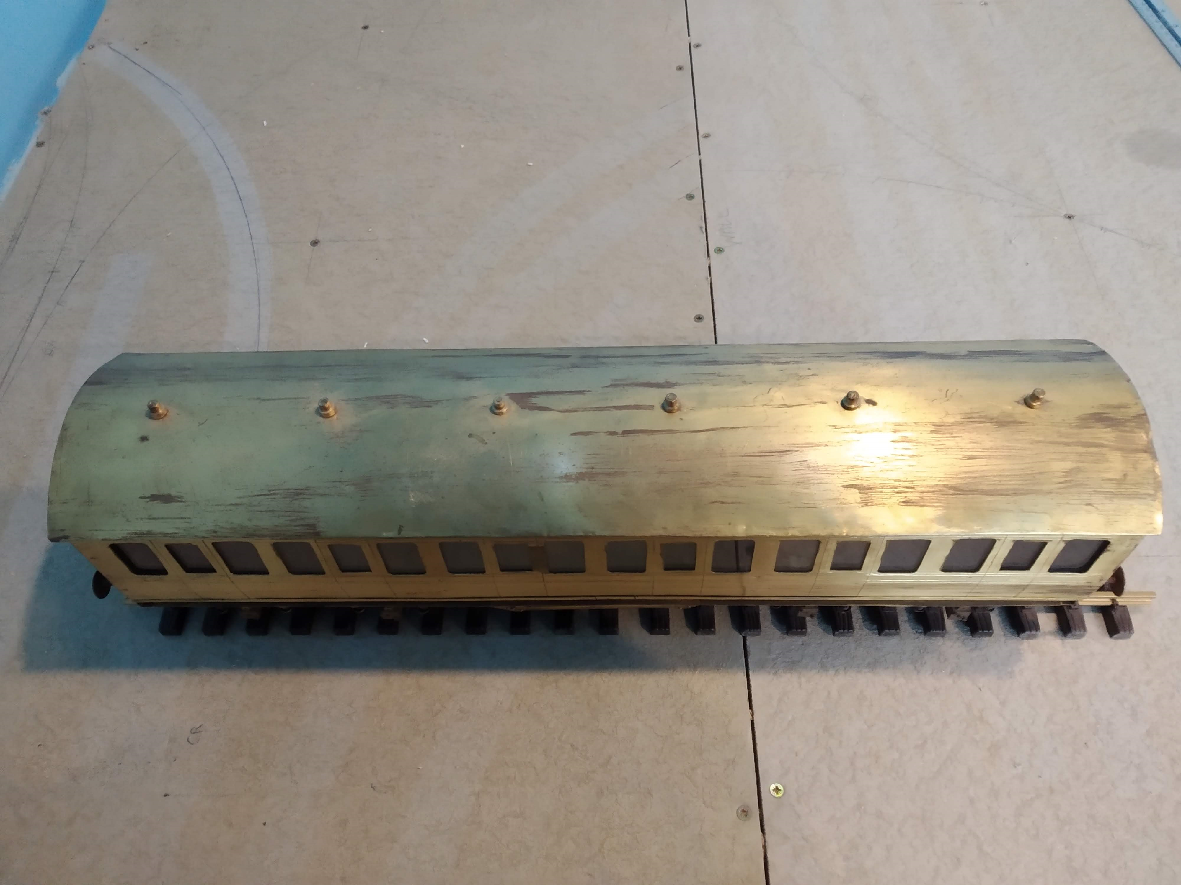
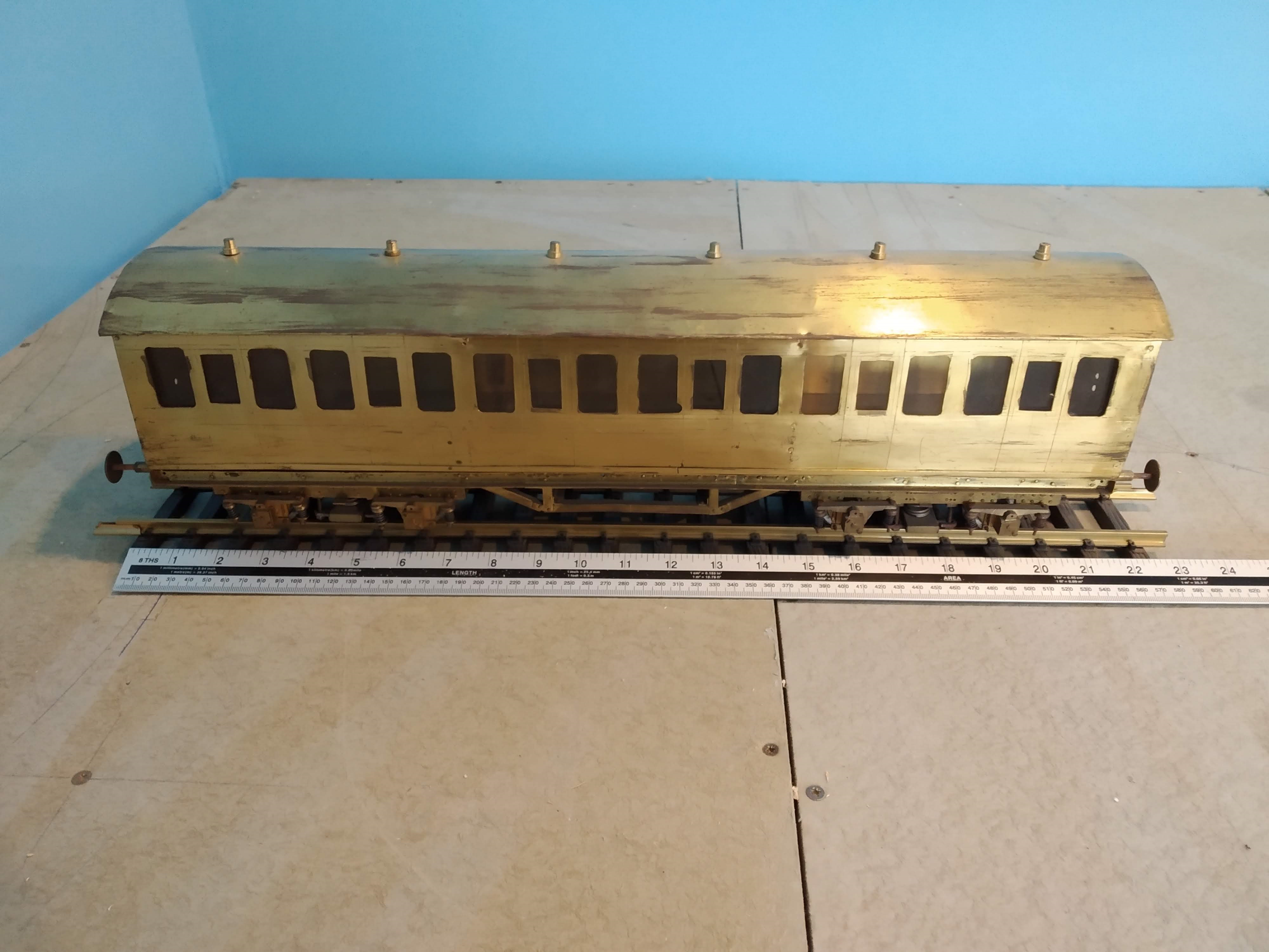
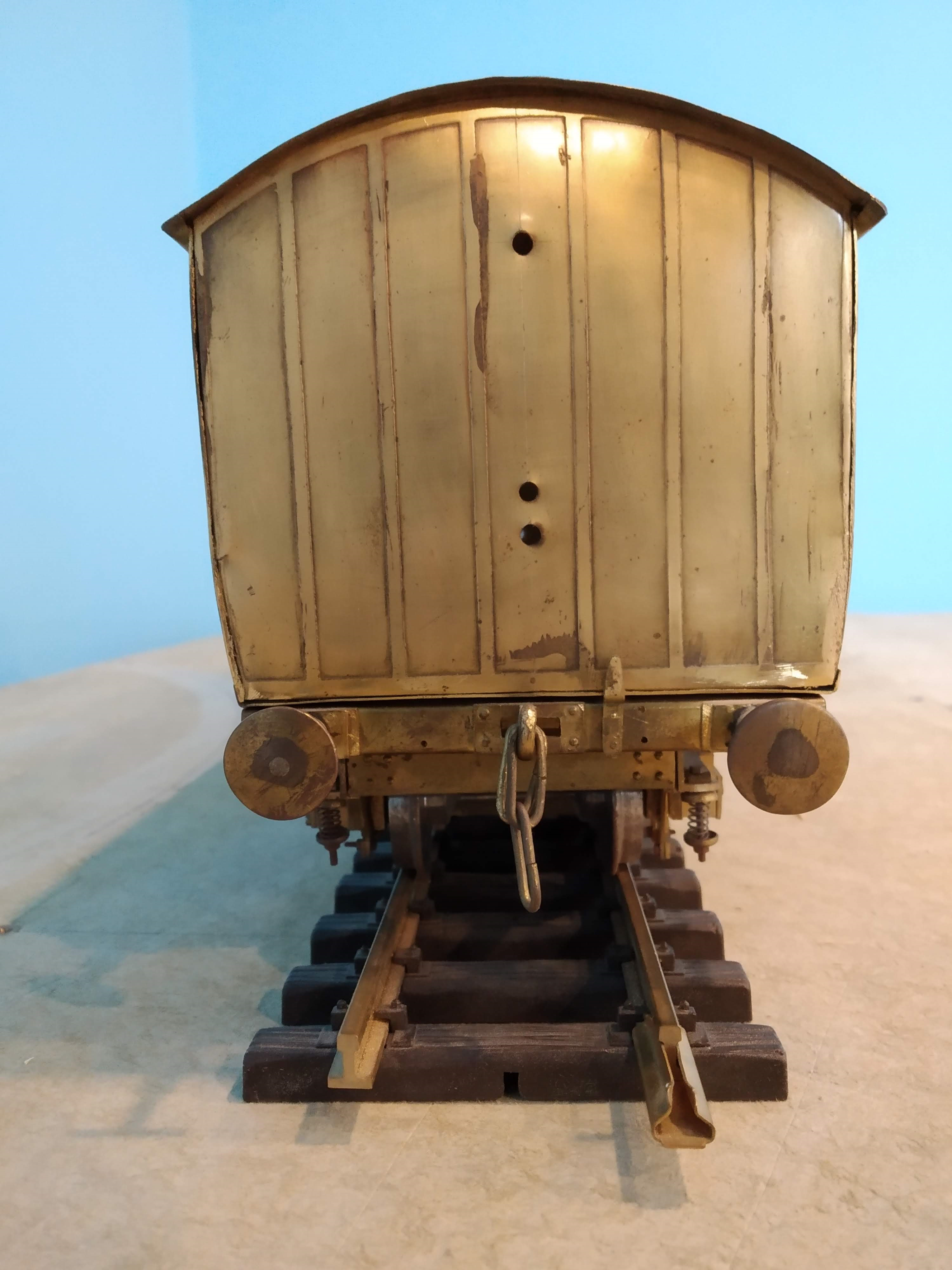
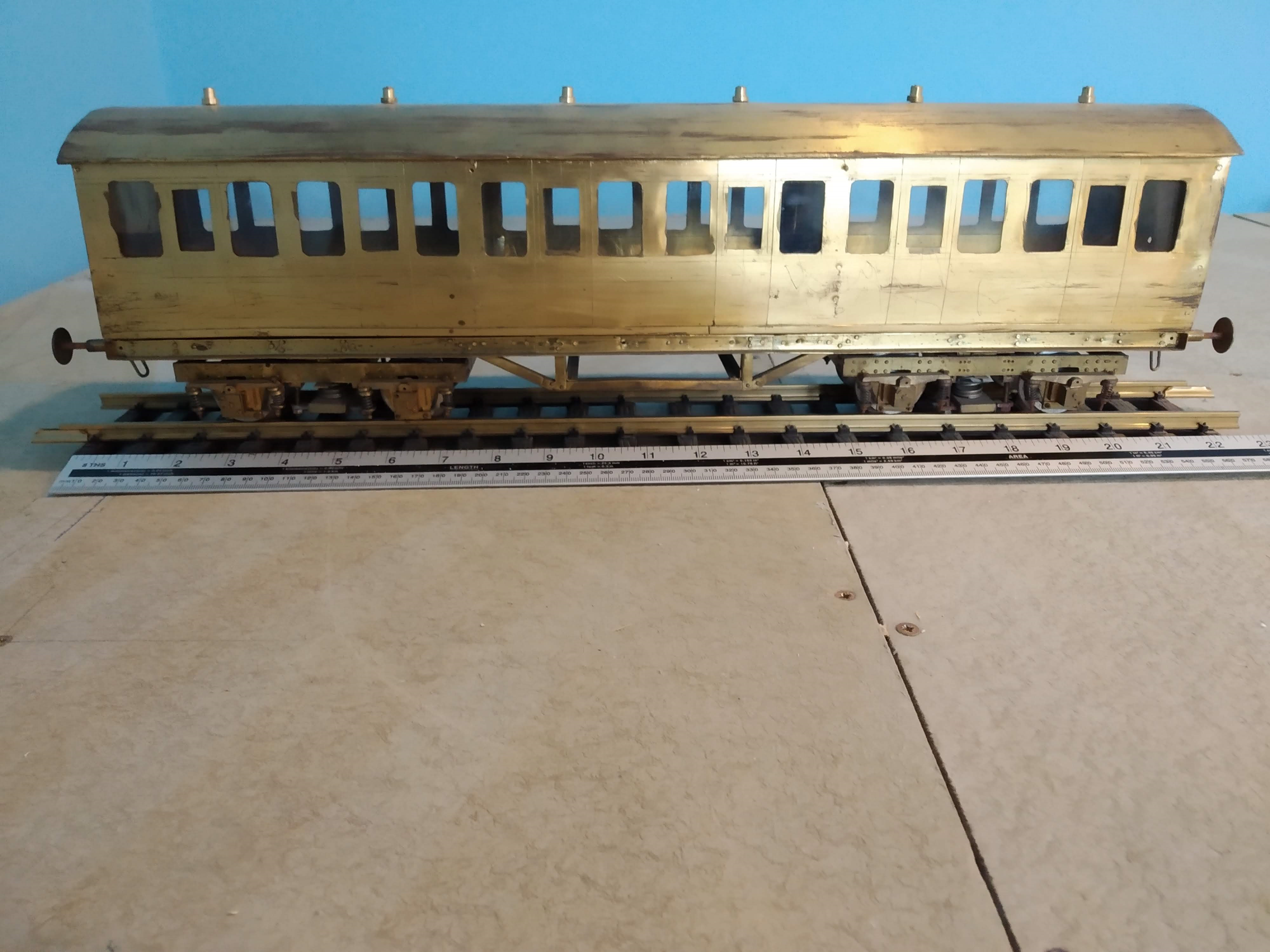
Hello Everyone, I attach some pictures of a brass coach built by the late Tom Tighe (known as Railway Tom). The coach was in Inchicore and I was asked if I could identify what it is. I am not very familiar with coaches and would appreciate any help please. I do not know the history of the model other than it is the work of Tom Tighe. It may have been built for training apprentices or as an example of the work that can be done at Inchicore. It may be that the model has no actual pedigree! The bogies are and the buffers are sprung and the whole model appears to be riveted or crimped (no sign of any soldering anywhere!). The track gauge is 45 mm and I have stood the coach on a piece of proprietary track. I have laid down a rule so the dimensions can be ascertained. There are 6 doors on each side and the sides appear to be identical. Thanks in advance.

-
As far as I am aware the first mechanical equipment used by Permanent Way on CIÉ were Massey Ferguson Tractors fitted with bolted on rail wheels. They could travel to site by road and be mounted on the track when the track was in possession of the Engineering Staff. They could also travel along the formation when the track was removed. They were used to lift (timber) sleepers (4 at a time) in or our of the line with a simple crane device which could swing to the side. They were also used to drag a simple harrow over the formation to break up the compacted surface prior to installing new sleepers etc. The harrow and crane were operated by the lift device on the tractor. Mobile vans were first introduced in the Dublin area in the late 1960s early 1970s. Thames vans were used I think. The choice and size of van chosen was influenced by the following factors:- Capable of transporting 5 to 6 men with tools etc. Capable of pulling s small trailer to transport additional tools and equipment. Capable of transversing famers fields in without causing damage to the land while fully loaded and hauling the trailer. Capable of fitting through railway accommodation under bridges. I hope this is of assistance.
-
The yellow buffer stops at the north and south ends of Fairview Depot are not hydraulic. They are Henry Boot buffers retrospectively fitted with standard buffers to their buffer beams in order to prevent damage to the scharfenberg couplers. Close inspection of these buffers will reveal that these buffers have fishplates fitted behind them and the buffers are are highly torqued. They were originally designed asslidig or friction buffers. However subsequent tests and trials on this design of sliding buffer revealed that they not behave as was predicted by the manufacturer. The buffers were removed from running lines and installed in sidings. Friction buffers currently in use are mostly supplied by Rawie in Germany. Earlier friction buffers were supplied by Godwin Warren in thr UK who manufactured under licence from Rawie.I believe Godwin Warren has stopoed trading. They also supplied level crossing barriers. Friction buffers operate by arresting the energy of a train and stopping the train at a rate of retardation deemed acceptable to ensure the safety of passengers on the train or waiting at the station. Passengers on the train may be standing up and collecting their belongings before getting off. Passengers may be queue along the platform waiting to board. Limiting the possible damage to rolling stock and infrastructure us also considered. The energy is burned off by the travel of the friction buffer. As the train slows down additional friction elements can be engaged to stop the train within the specified length or distance. The standard length of run out afopted by Iarnród Éireann is about 12 metres.
-
Irish Standard for Clearances to Structures Modelling Dimensions
eugenepfox replied to eugenepfox's topic in General Chat
Thank you Colin R and Mayner. I am hoping to produce an Irish version of model standards dimensions andclearances for 4 mm scale as I am planning to start constructing a model railway shortly. I am using RTR models on 16.5 mm track. Do you think thereis merit in makng the information available to / publishing it on this site for everyone. Thank you, Eugene -
Irish Standard for Clearances to Structures Modelling Dimensions
eugenepfox replied to eugenepfox's topic in General Chat
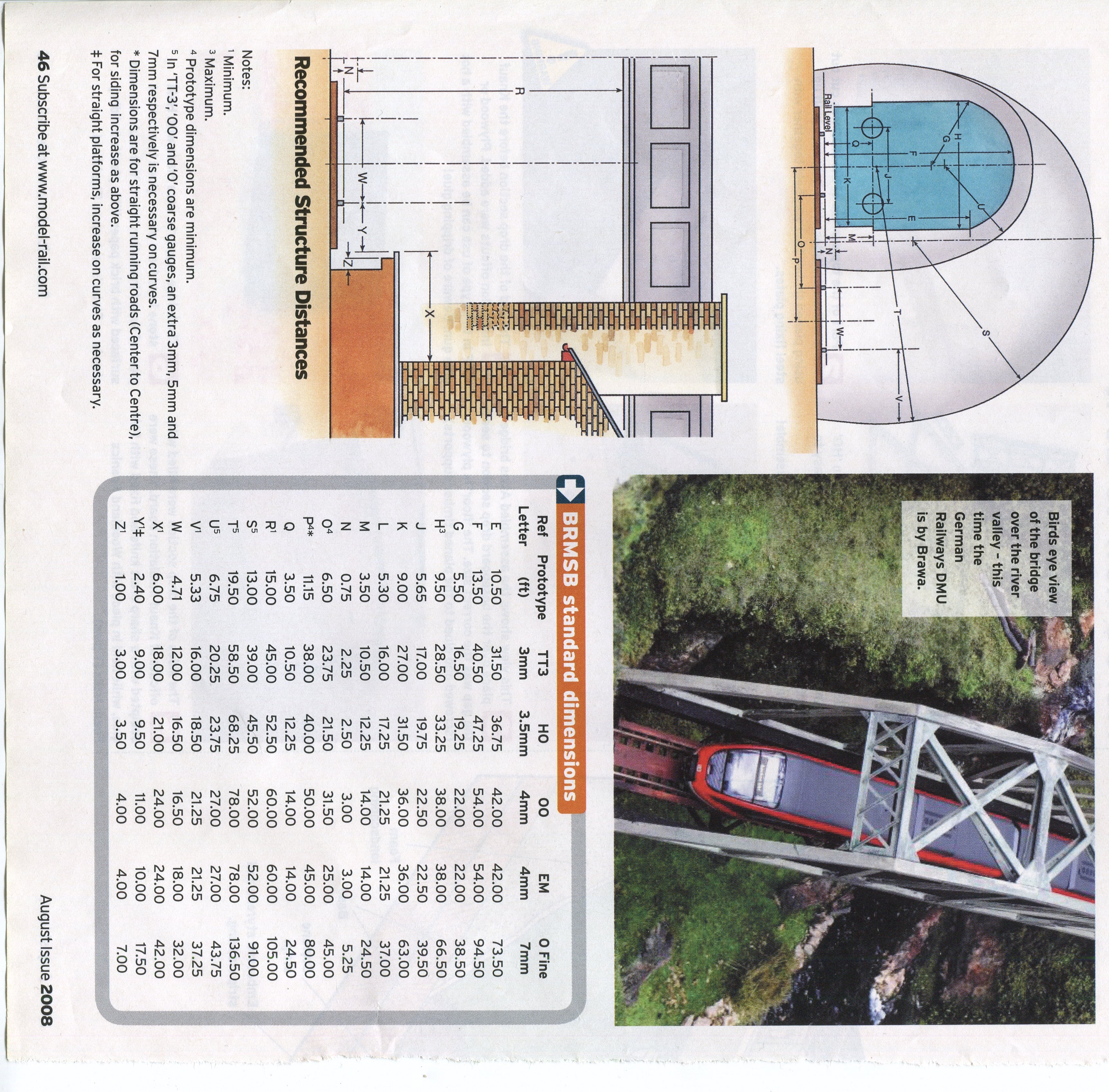
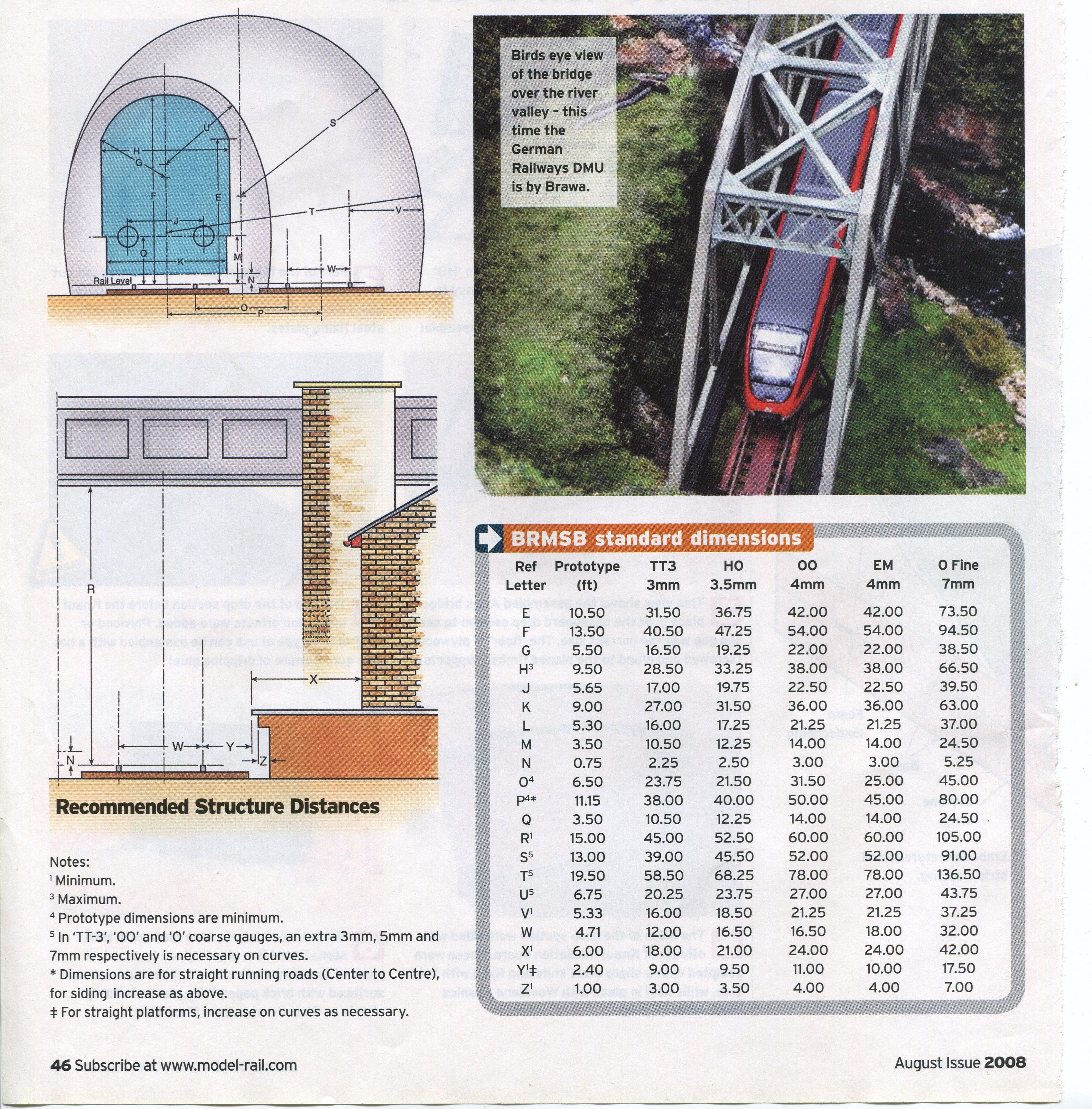
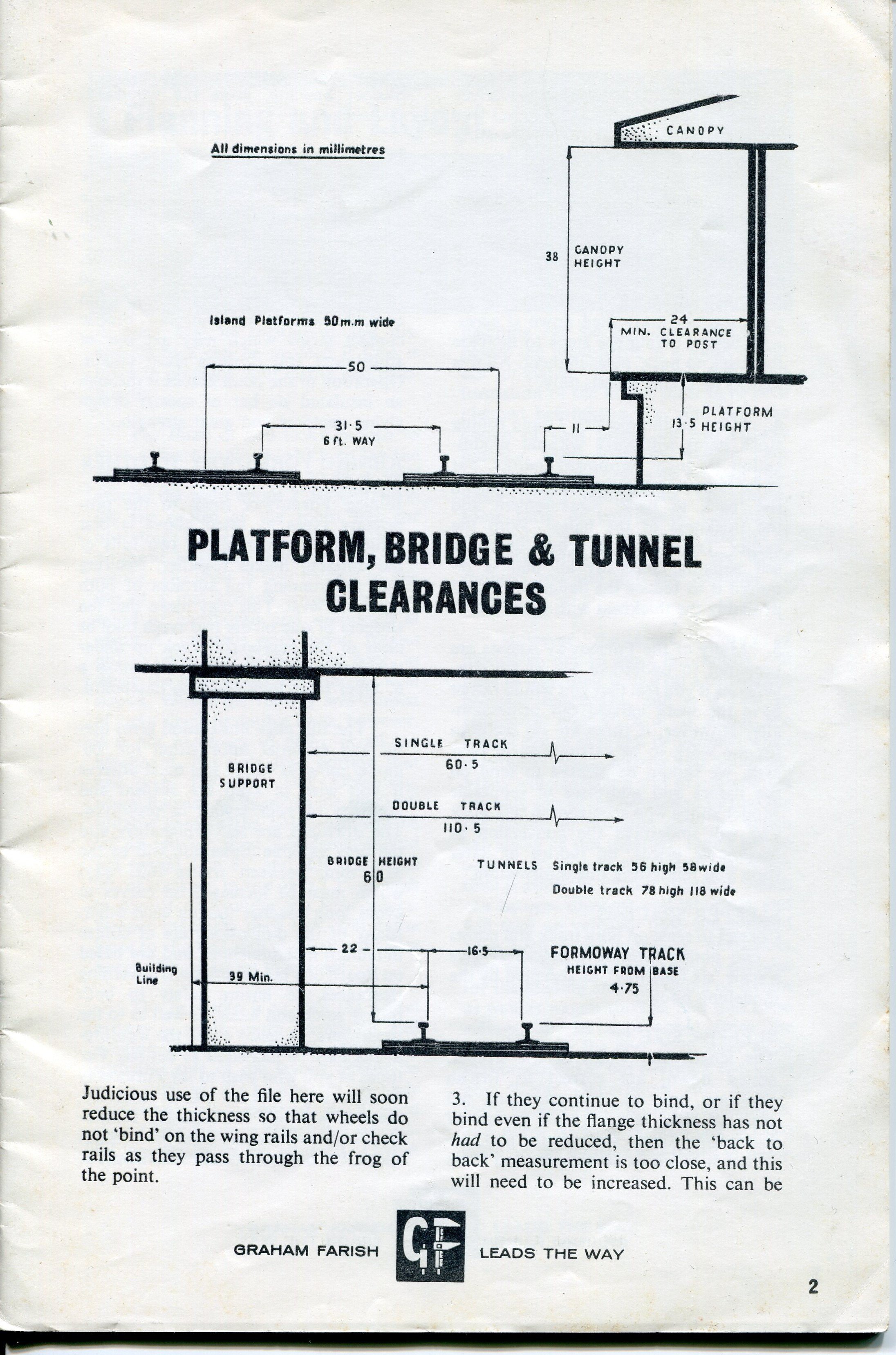
Apologies if my question has caused confusion. For information I attach an extract from a now out of print Graham Farish Handbook (scale OO gauge) and the 2008 August issue of Model Rail which illustrates the British version of what I was trying to find relative to Irish practice. I am researching the topic and will share my work if anyone is interested but what I am trying to establish is if the work has already been done by others.
-
Irish Standard for Clearances to Structures Modelling Dimensions
eugenepfox replied to eugenepfox's topic in General Chat
Thank you all for taking the time to respond and for the information supplied. The reason for my enquiry was to try to establish if there was a similar schedule of dimensions set out for Ireland as the BRMSB set out for standard gauge railways for Platforms, Buildings and Bridges. If you watched the model railway challenge programme on Channel 5 on Friday evening you would have seen that one of the teams had to realign a section of curved track as coaches on concentric curves collided with each other due to inadequate clearances being provided. American and European standards set out requirements for curved tracks. I am not aware of any OO gauge standards available for curved track! The BRMSB for dimensions for Platforms, Buildings and Bridges as set down for standard gauge railways are not I believe appropriate for models of Irish railways due to the fact that Irish prototype coaches were wider that their standard gauge counterparts. For example the widest coach used in Ireland were the Park Royals which had a maximum width of 10 ft 2 in being 8 in wider than the standard coaches used on standard gauge. I fully appreciate the point about clearances having to be increased to cater for curved and canted track and also vertical curvature. I believe the vehicle (in revenue earning service) with the greatest distance between bogie centres are the pocket wagons with a bogie centre distance of 17000 mm. I purposely stated revenue earning service to exclude departmental stock such as a ballast cleaner or the like The standard distance between bogie centres for Intercity stock is 16000 mm and for Suburban / Commuter stock is 14100 mm approximately. Intercity stock generally has the passenger access doors at the ends of the vehicles which can be problematic for stepping gaps when the platforms are curved e.g., Cork where as Suburban / Commuter stock generally have the (wider) passenger access doors at or near the bogie centres to minimise the effects of centre and end throw when platforms are curved. On a section of curved track a vehicle will need additional clearance to cater for the centre throw (overhang at the middle of the vehicle) and end throw (overhang at the ends of the vehicle). The European standard for model railways uses a value equal to twice the centre throw to widen the interval between tracks. So following the same logic this would equate to a vehicle overall length of just over 24 metres which is a little longer than any vehicle currently in use in Ireland. Mention has been made of the "big overhangs at the front" and I believe that ICRs have an overhang from bogie centre to cab end of 4000 mm, so the maximum end throw such a vehicle would generate is the same as a vehicle with an overall body length of 4000 + 16000 + 4000 = 24000 mm as stated above. On a section of curved track the interval between the tracks must be increased by an amount equal to the sum of the end and centre throws in order to preserve the clearances. Similarly if there is a platform on a curved track, the lateral clearance needs to be increased by an amount equal to the end throw or the centre throws in order to preserve the clearances. Depending on whether the platform is on the inside or outside of the curve. Allowances for the effects of cant must also be made. I apologise if the above is long winded, but as someone who worked in 1 to 1 scale for over 40 years and am how hoping to build an OO scale model railway using RTR Irish equipment I am anxious to get it right first time!! In due course, if there is a desire for it, I will post details of the standards I have adopted (together with the reasoning for same) for the benefit of the group. I would only be setting out recommendations for the area above rail level and many recommended dimension will be specified from track centre line rather than a rail, as this will suit people who use 16.5 mm track for RTR stock and also people who have adopted 21 mm as their standard . Vertical clearances will of course be relative to the top of the rail. It is my belief that RTR stock has wheels compliant with both European (and American standards) and are designed to negotiate a minimum radius of 438 mm (R2 in sectional track). I look forward to any further views and in particular if an Irish version of the BRMSB standards for Platforms, Buildings and Bridges would be useful to the group. Thank you for taking the time to read this post and should need any clarification etc. please just ask. -
Please advise if there exists anywhere a schedule of clearances for scale 4mm = 1 Foot ( Ratio I:76.2) setting out lateral and headroom clearances to structures based on Irish Railways practice. I am aware of American and European modelling standards for HO scale (Ratio1: 87.1) and also the BRMSB standards for Platforms, Buildings and Bridges. In the USA double stacking of containers on rail bogies is commonplace as is double decker trains in Europe. As neither of the above could operate in Ireland the adoption or reconfiguration of American and European modelling standards would not be appropriate. I would welcome any information or views on this matter.