Paddy Mac Namara
-
Posts
186 -
Joined
-
Last visited
-
Days Won
1
Content Type
Profiles
Forums
Events
Gallery
Blogs
Everything posted by Paddy Mac Namara
-
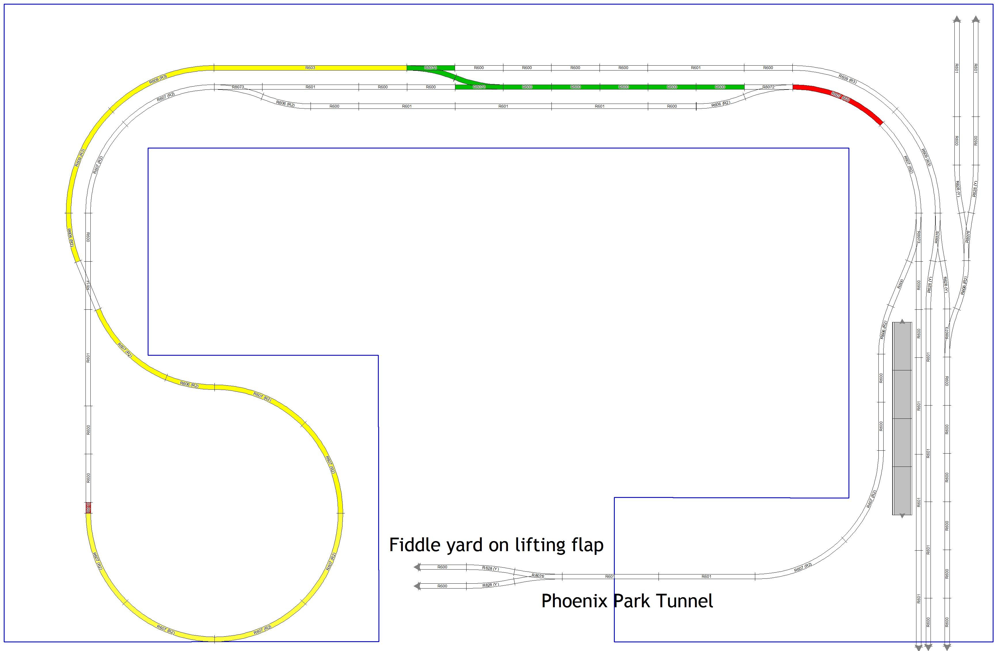
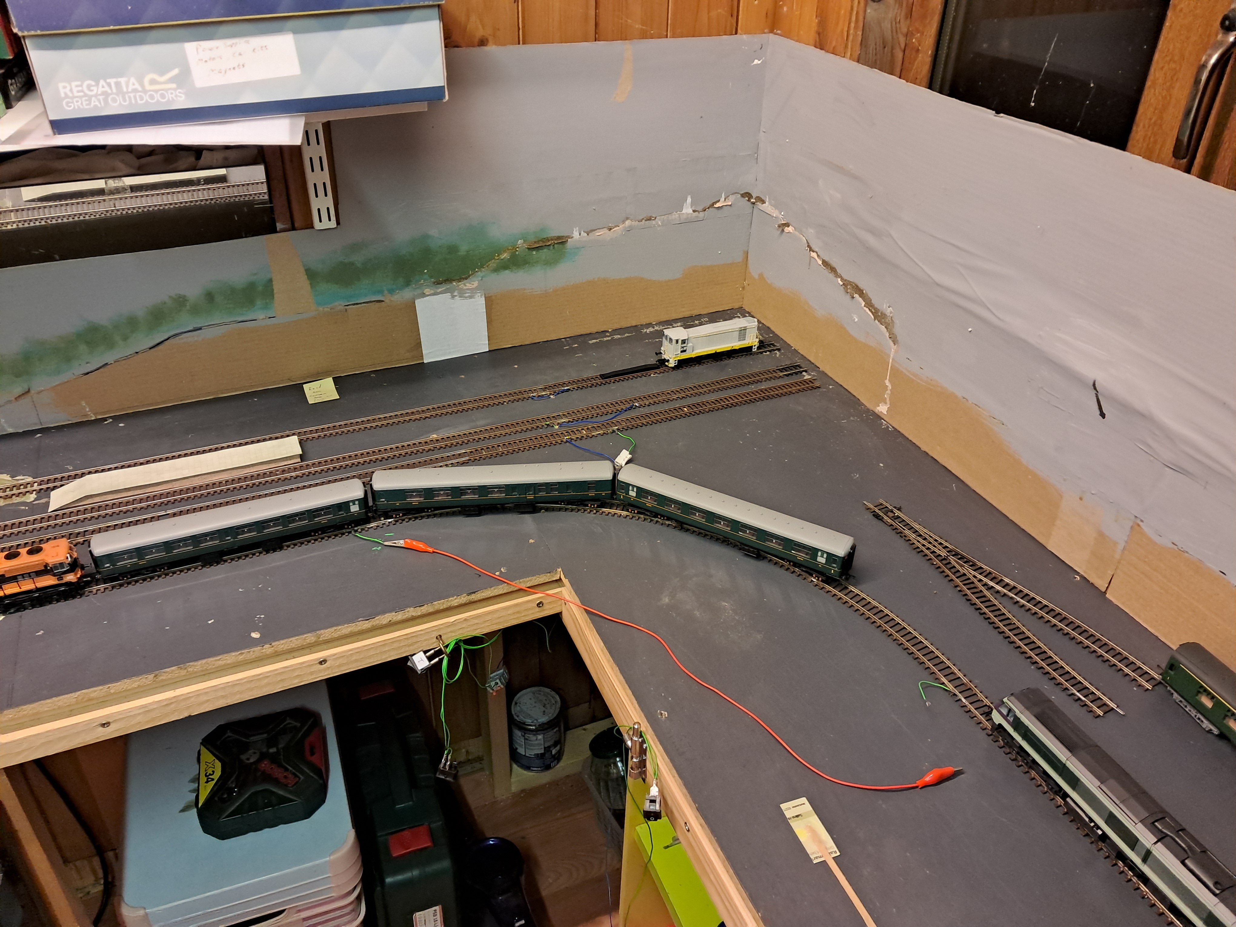
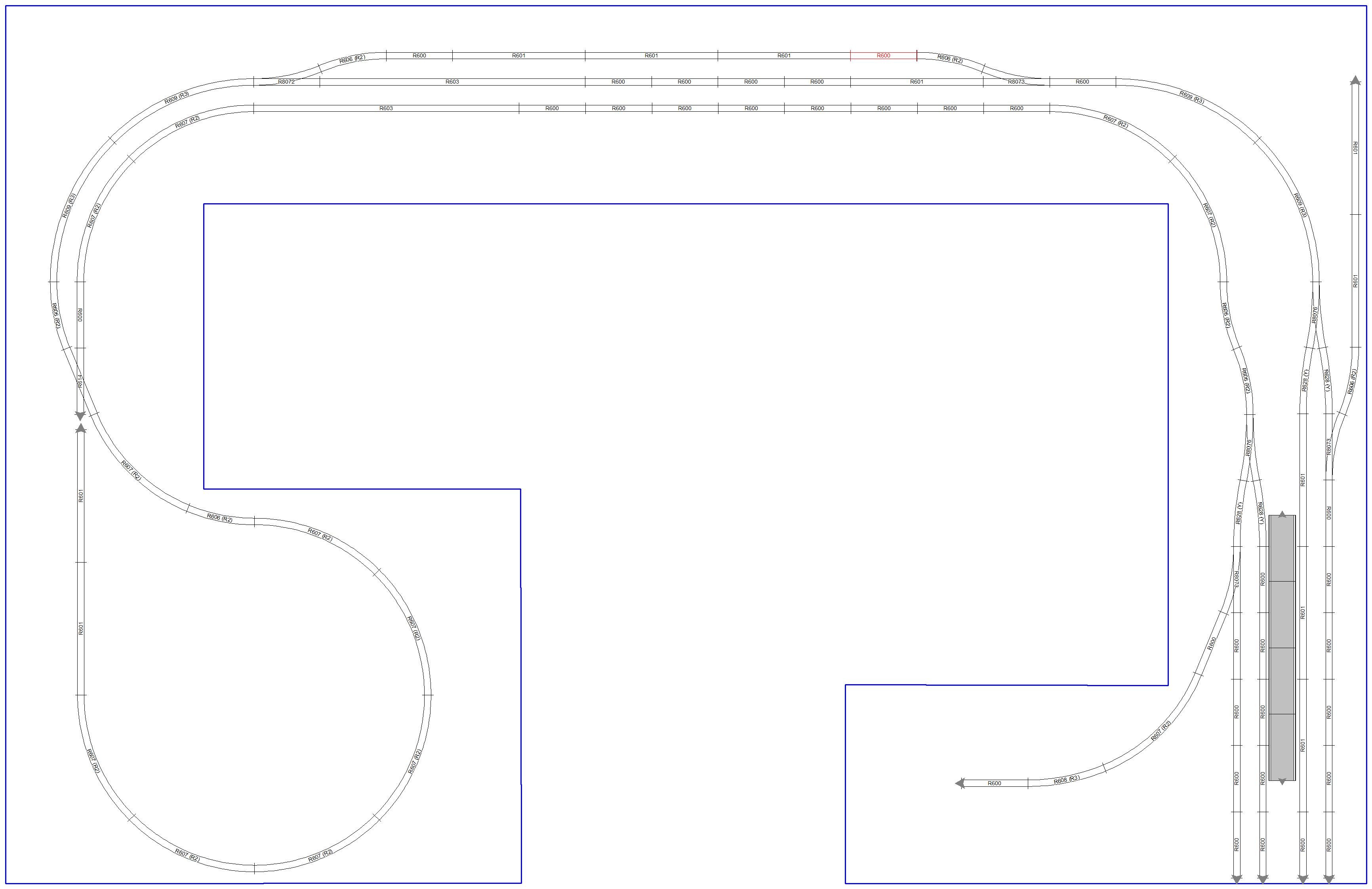
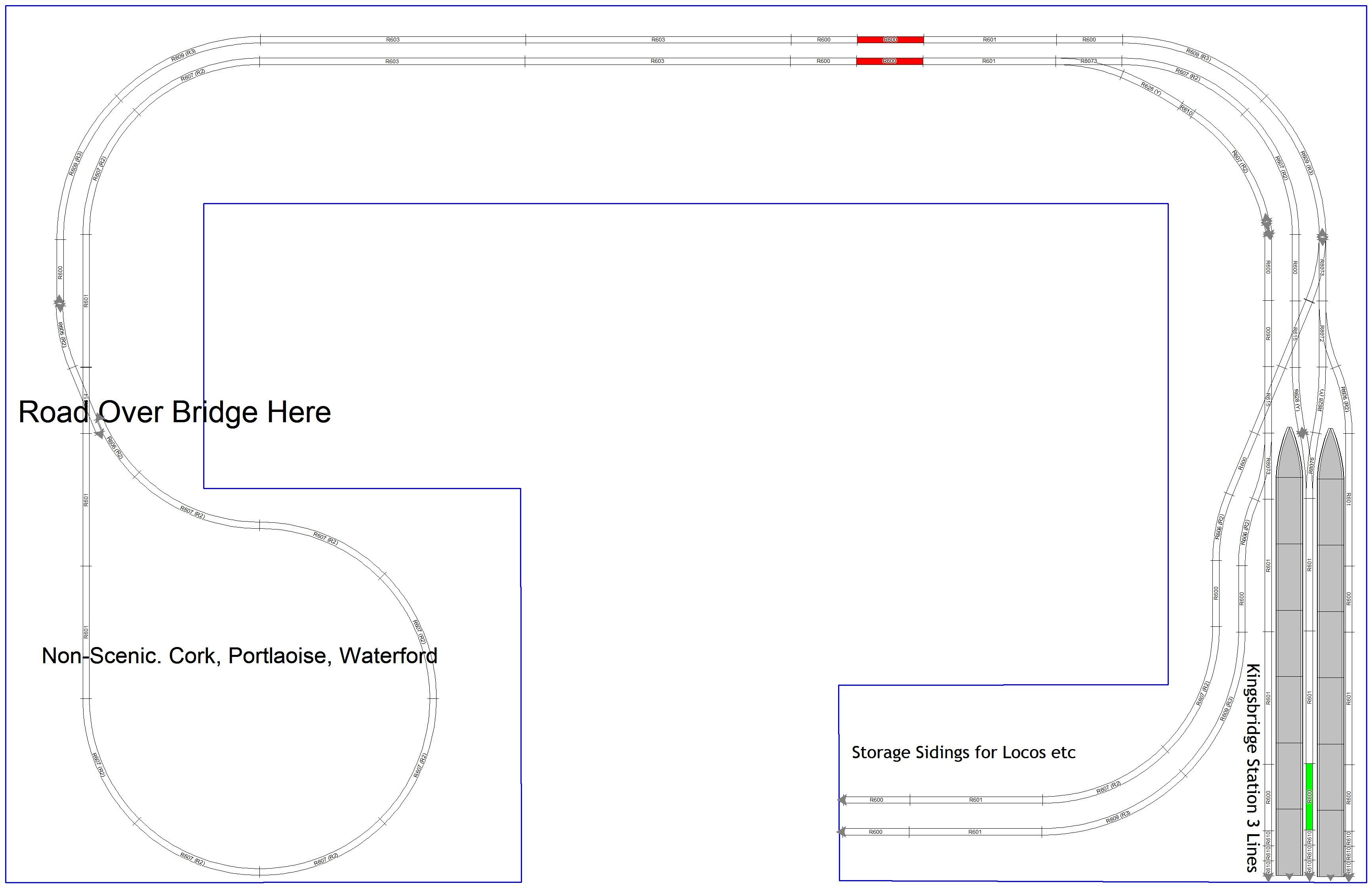
I have included a cross-over from up to down as suggested (thanks). The return loop has isolation gaps on both rails, shown in red. Power is fed to down from red curved track. I can isolate the up part of the return shown yellow. Switch the points at the cross-over and bring loco onto downline without any shorts via the green tracks.

-
Thanks
-
Thanks, very useful. I'll have to investigate some options.
-
thanks
-
when is next model fair? Ta
-
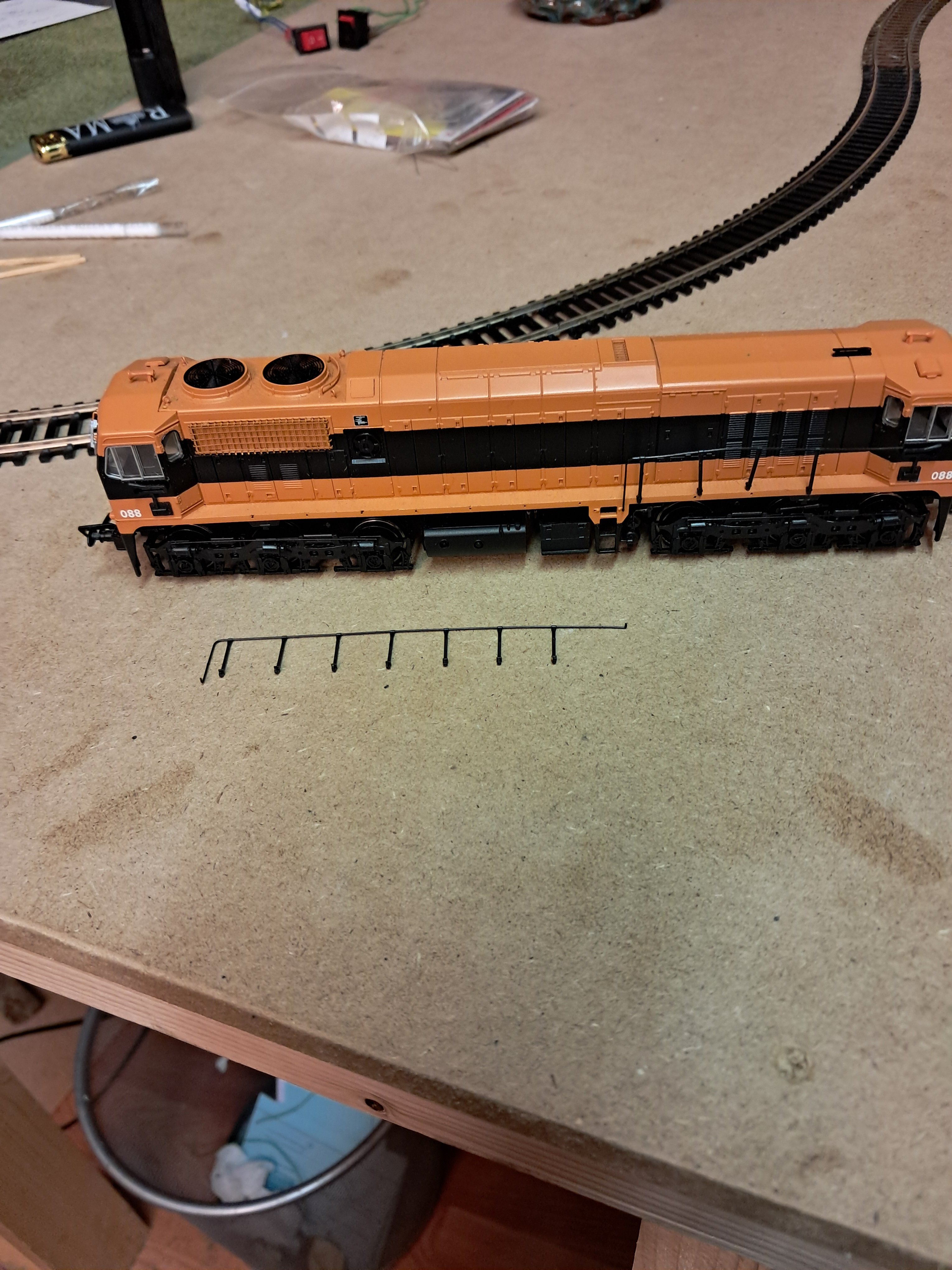
Any suggestions how to re-attach these railings, superglue? Fiddly little feckers and i am careful taking them out of box,
-
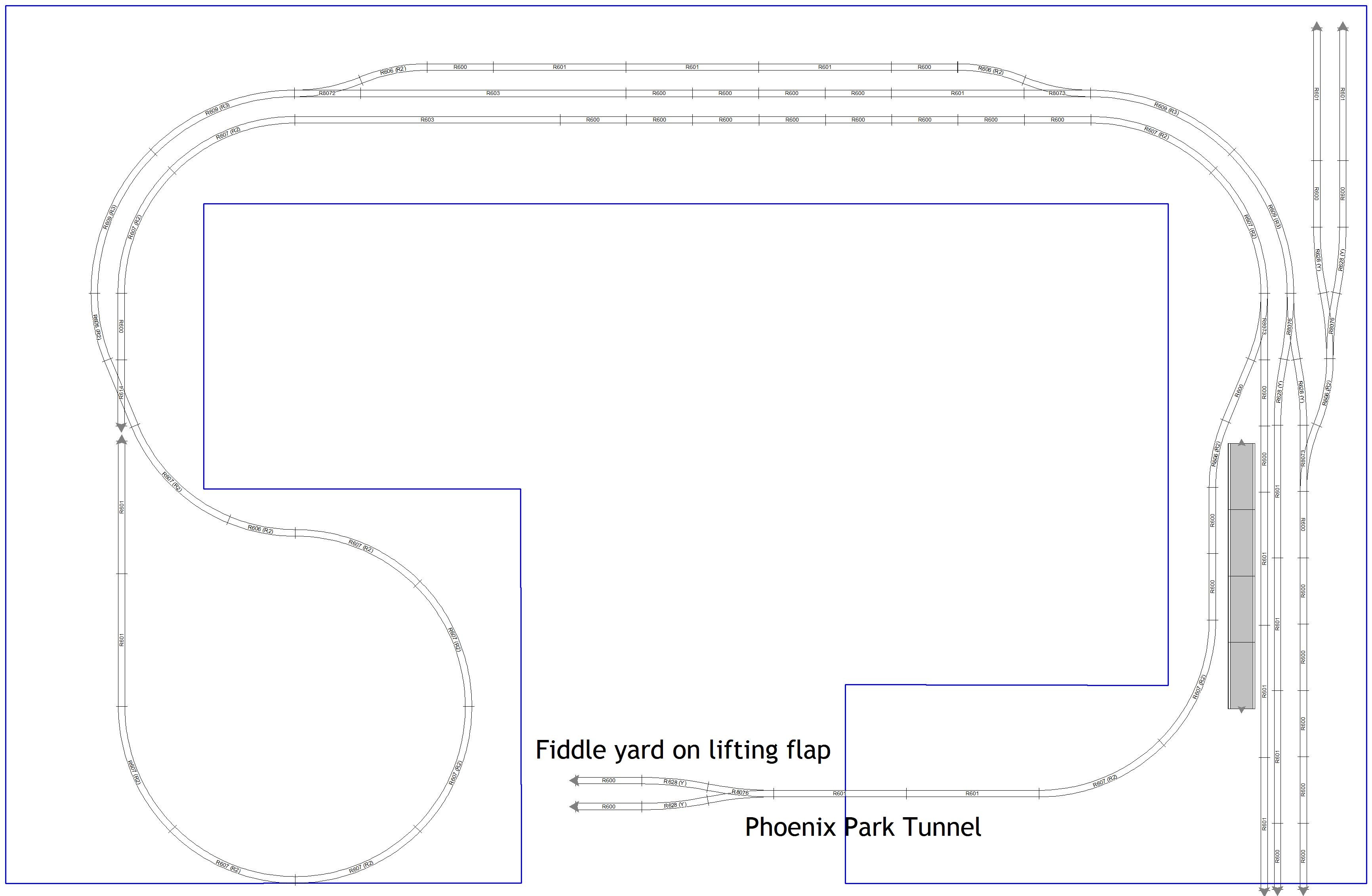
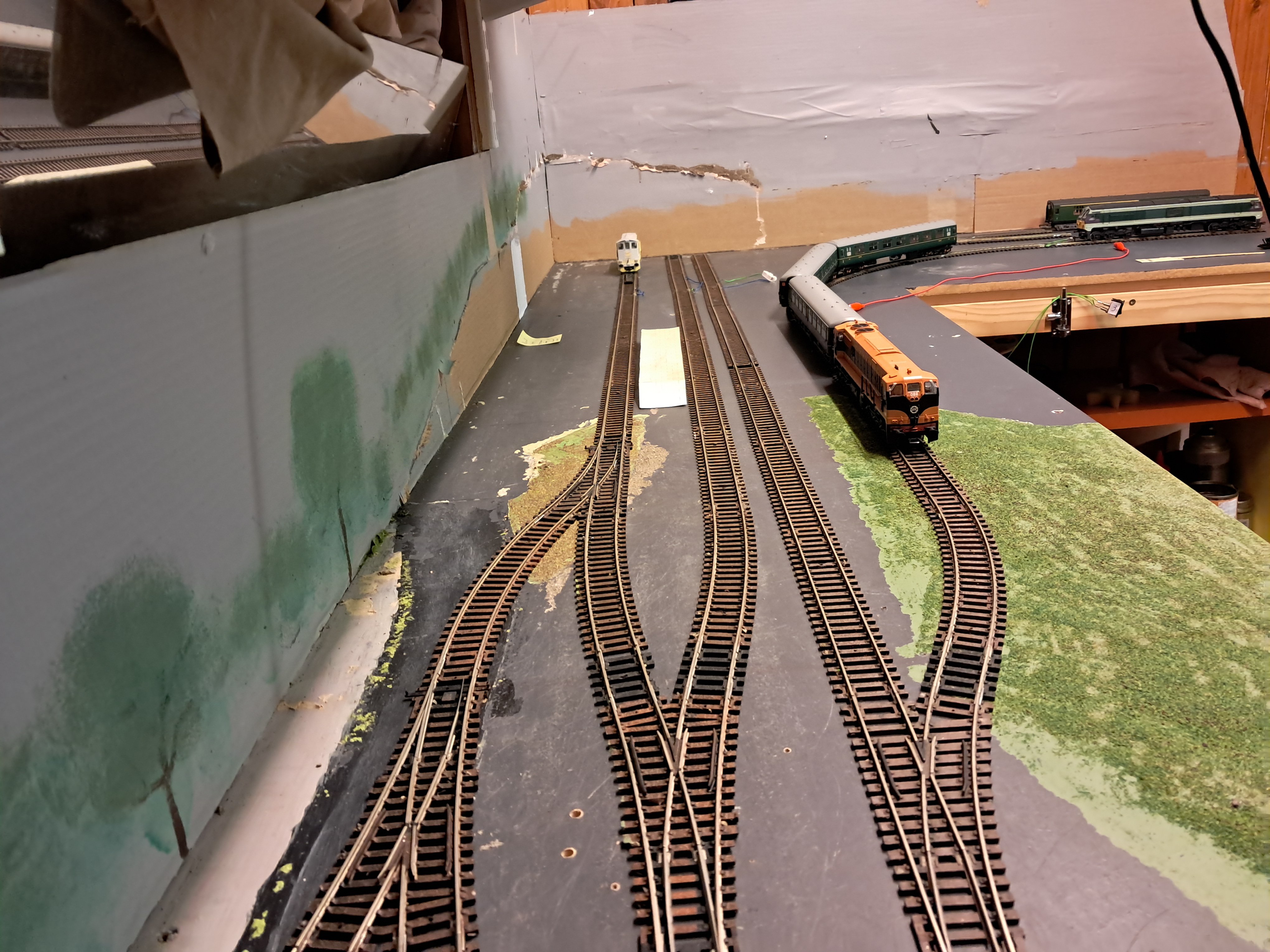
This gives me 4 platforms at station. However when i did a few test runs with locos and carriages, i realised that at best i'll only get about three carriages to fit. So ive gone with 3 platforms in this new iteration.
-
-
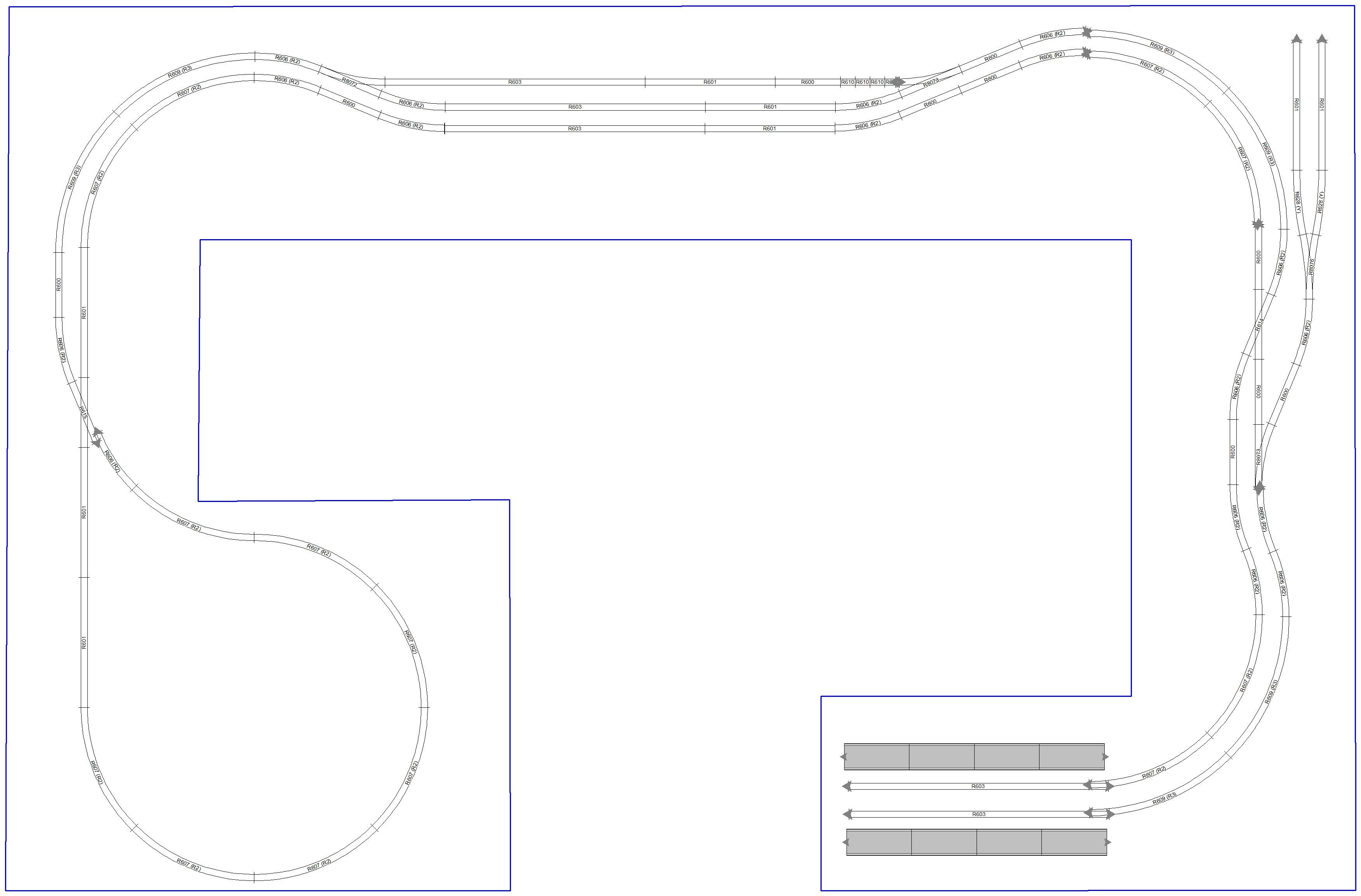
I'm not straying far from home with my layouts, hey stick with what you know. I've been using the Dub-Cork route since a child. So that Y junction causing way too many comlplications with shorts and just way too many isolated sections to keep track off. So this is next track plan.
-
Not push-pull if my understanding is correct. Anytime i push carriages or wagons they always seem to get snarled up and uncouple or derail. Locos will enter platforms at station "head" first. Then uncouple carriages. Another loco will come from storage sidings (Inchicore) and couple to carriages in station and off it goes again. Lone loco will then goto Inchicore. Work in Progress
- 38 replies
-
- 10
-

-
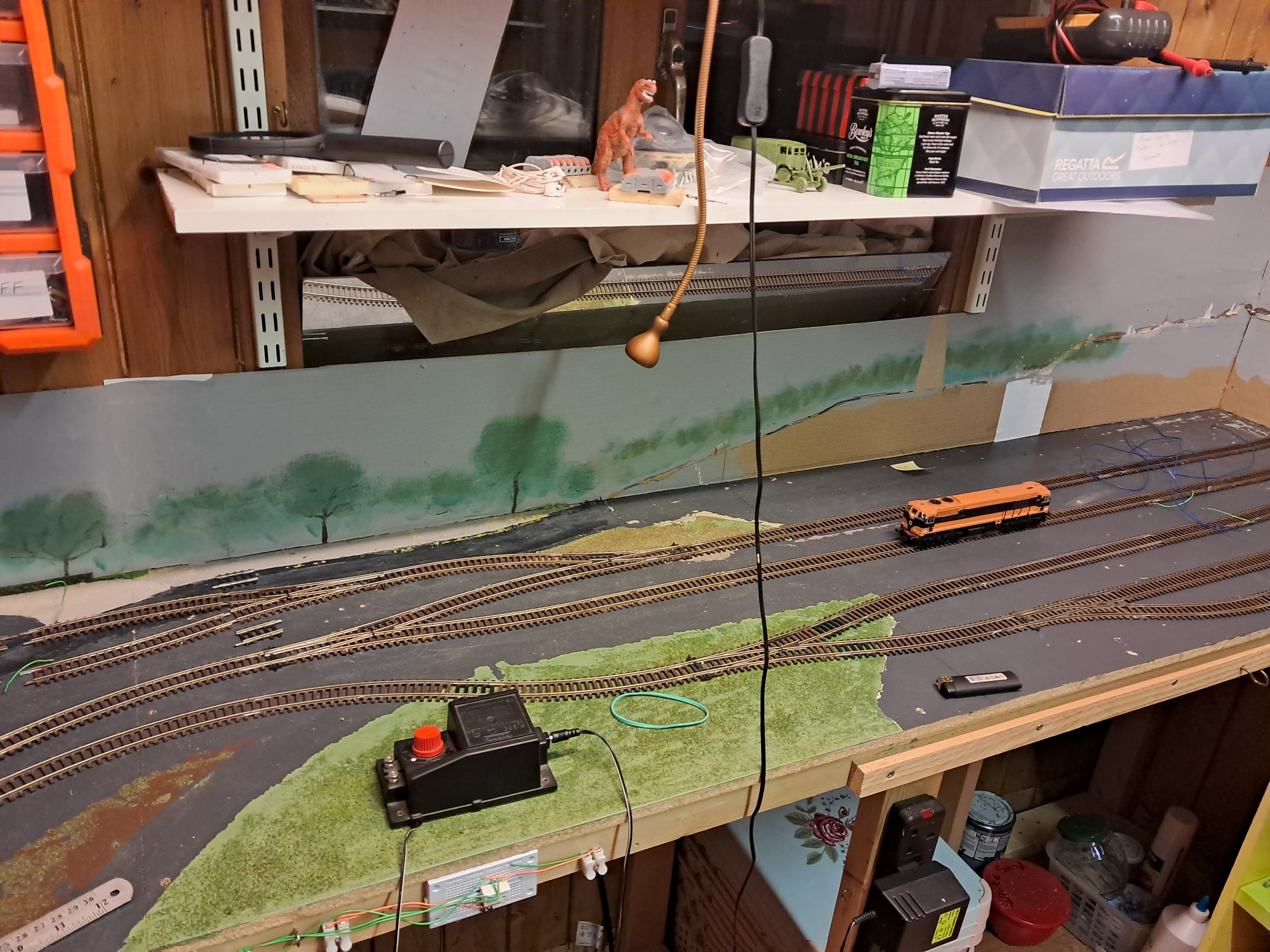
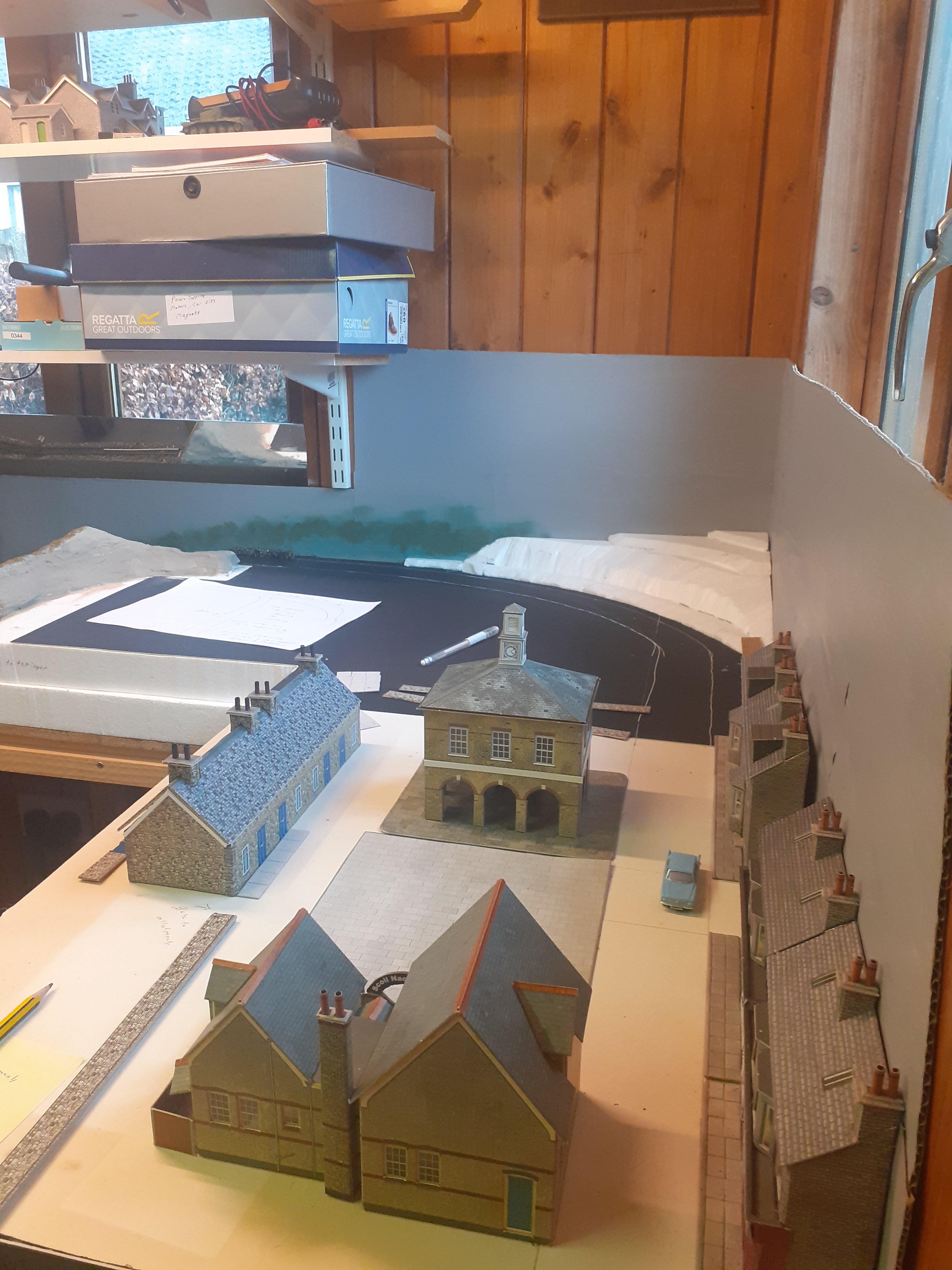
I do no whattocallit. “Kingsbridge”. I wanted a terminus station like Heuston, with the return loop hidden by a scenic break, probably road overbridge. I run trains to Cork and then they return. What we think will fit in our heads and what actually fits are two different storys. Now I have a fairly big room for my layout, however the first plan doesn’t work, not enough room for platforms with a least 3 carriages. I have revised it as shown. Because the return loop is done with diamond crossing there was no issue with electrical short circuit. However, the introduction of the Y junction creates a continous loop. I like the symmetry of the Y junction and it allows for two decent sized platforms, with 3 lines. Currently, and I’m still just playing around, the single power controller is located at the green track in the middle line. To prevent short circuits, I have used isolated tracks shown in red as per Hornby Track Plans 8th Ed (£4.99) P. 30. Lots of switching on/off isolated sections depending on which arm of Y junction is chosen.
-
Irish
-
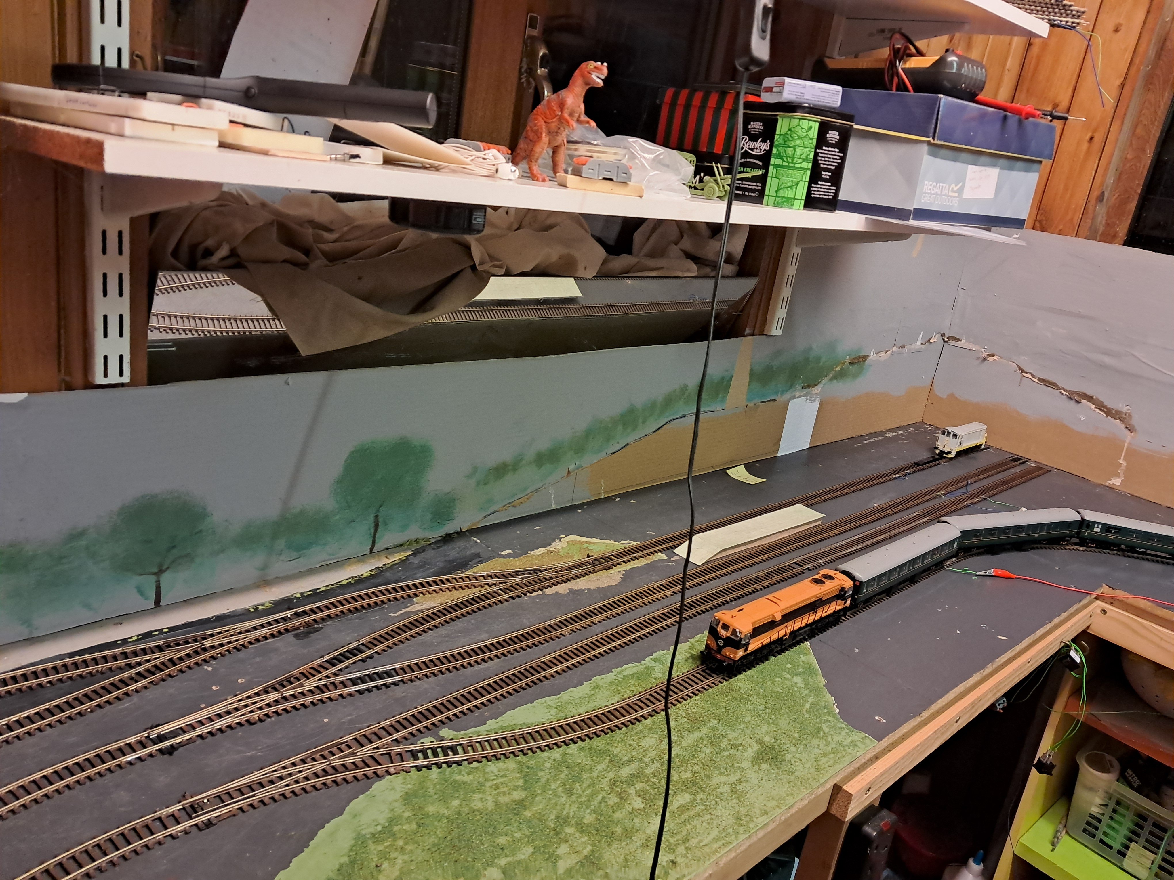
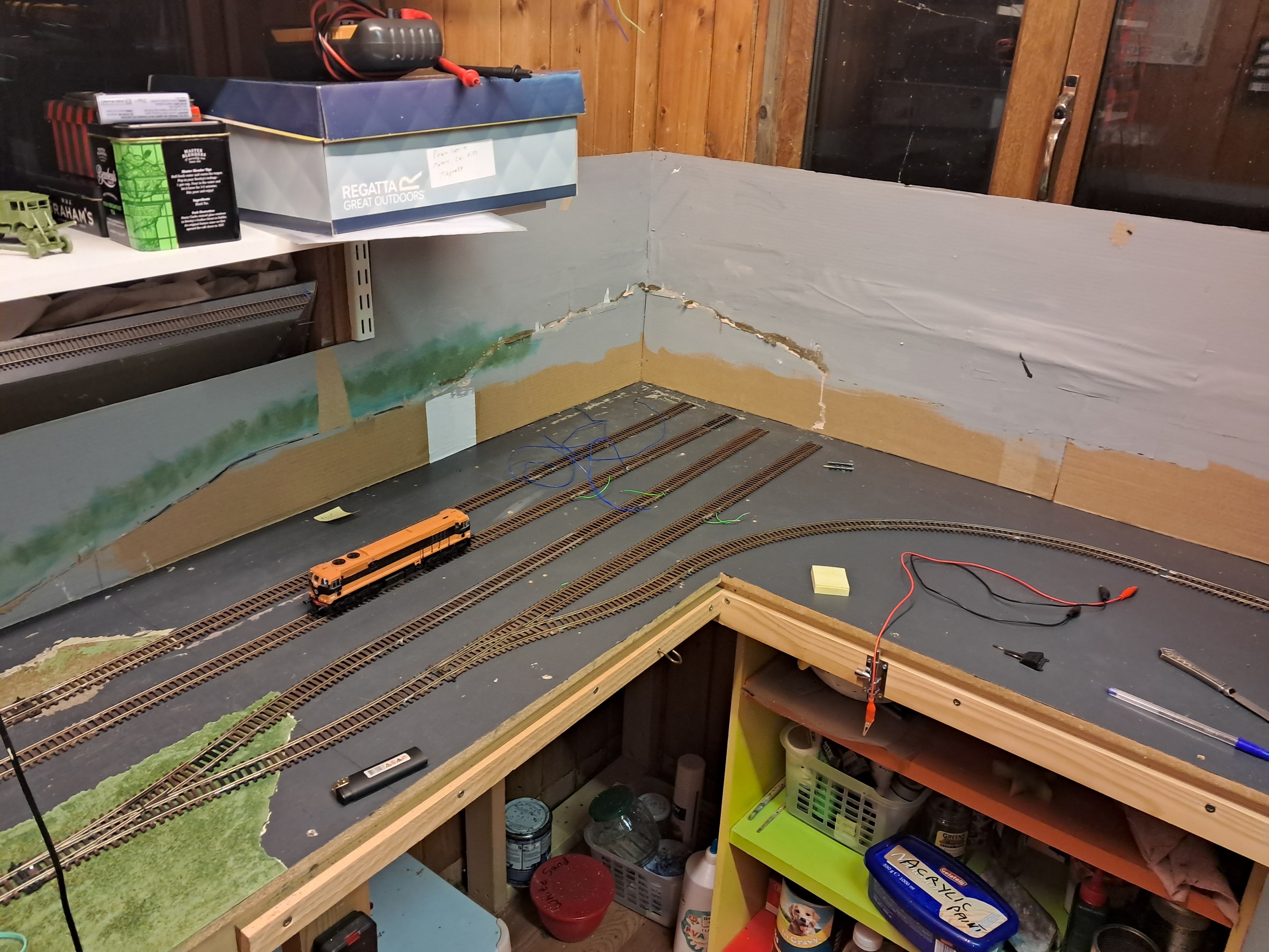
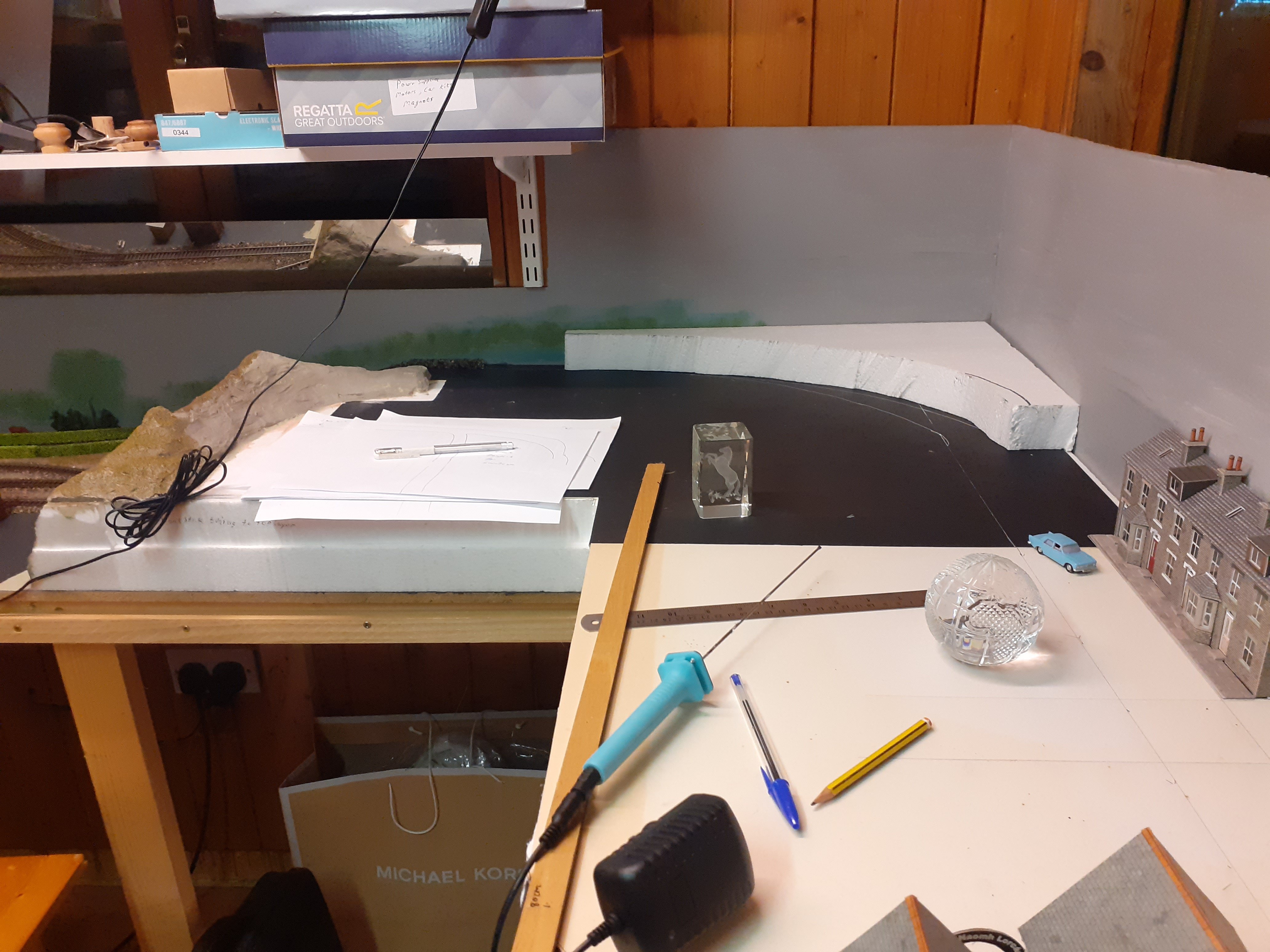
New Layout Description: Celbridge started April 2016 is no more, I’ve lifted the track and started afresh. My shed is 3.4 m x 2.2 m and the layout is to run around the circumference. Depth of layout is 500mm all the way round. I have it set at a height of around 760mm so that I can sit comfortably in the chair and work away at it. Unlike Celbridge this layout is going to be end to end. Experimenting with track plans at the moment. I have added an extension to baseboard for return loop (non scenic) at one end and terminus station at the other end. Here is track plan.
-
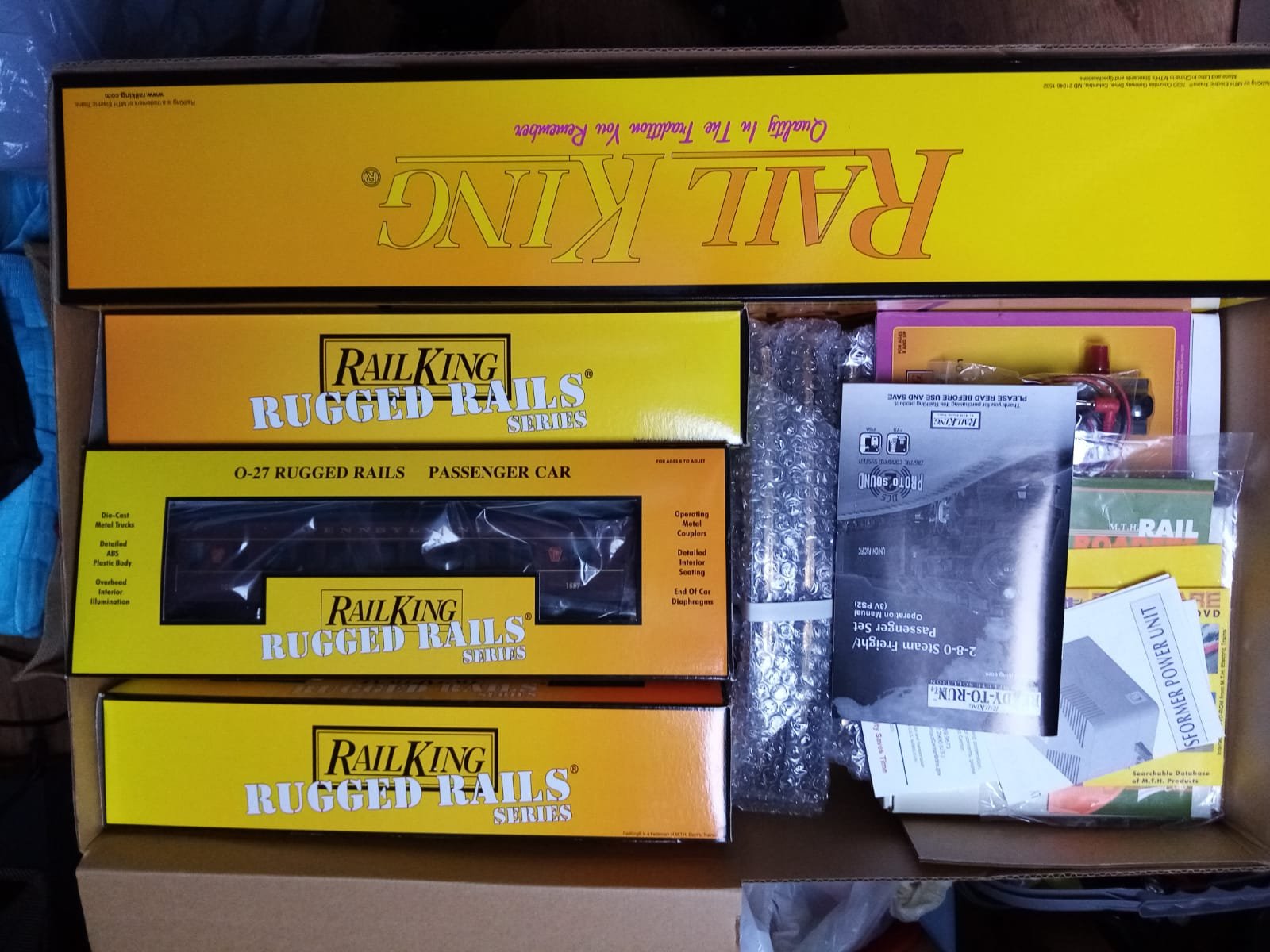
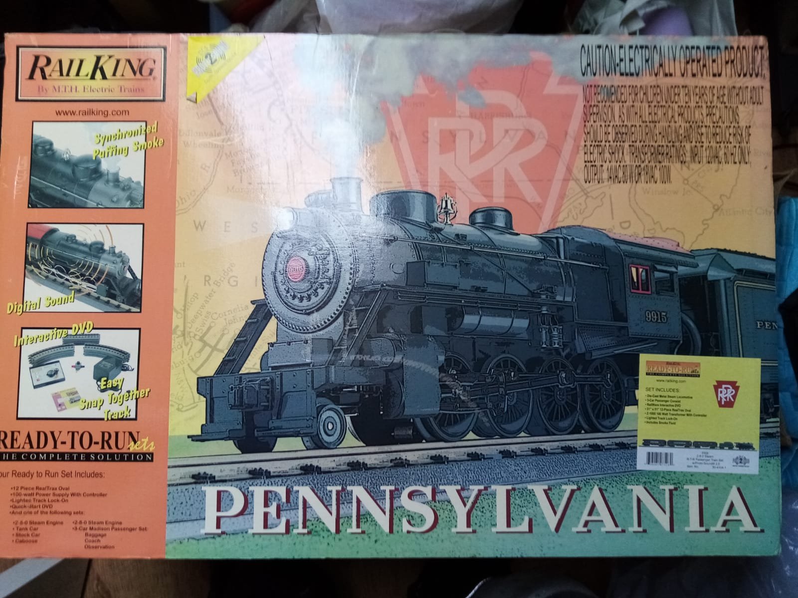
For Sale American Train Set BNIB
Paddy Mac Namara replied to Paddy Mac Namara's topic in For Sale or Wanted
thanks -
This is an unwanted gift of my carpenter Jim. Was wondering if any interest in it here, or any suggestions where i could sell it. I'm not sure of the scale, this link appears to be similar: https://mthtrains.com/30-4244-1 Paddy
-
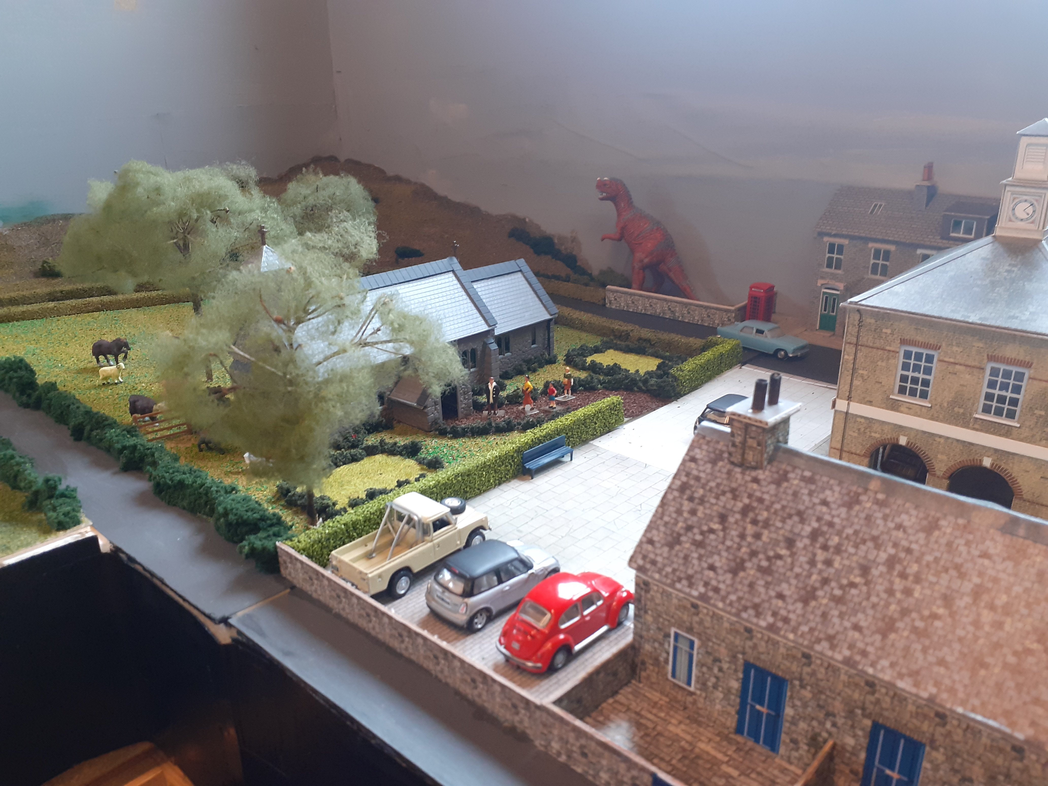
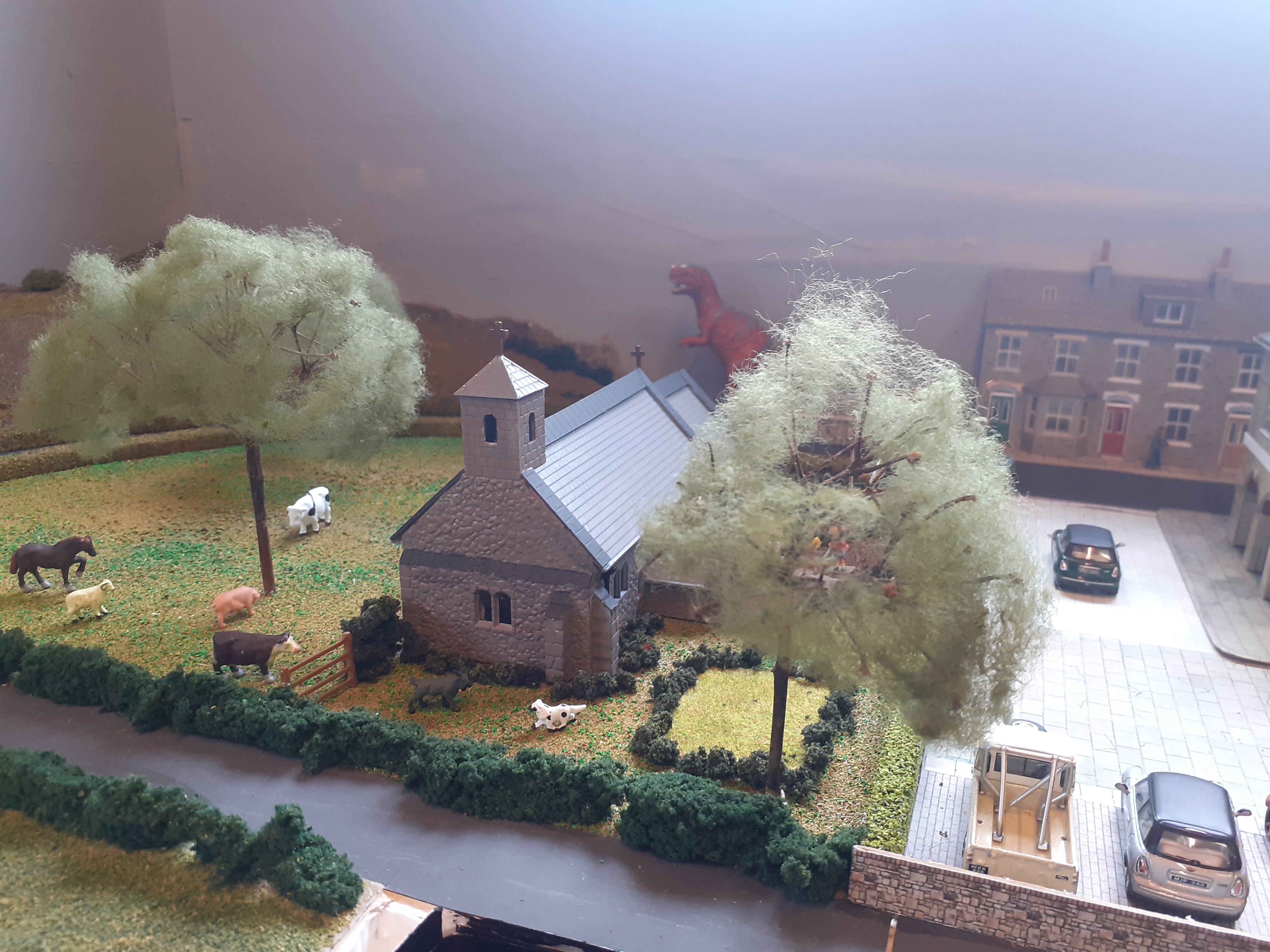
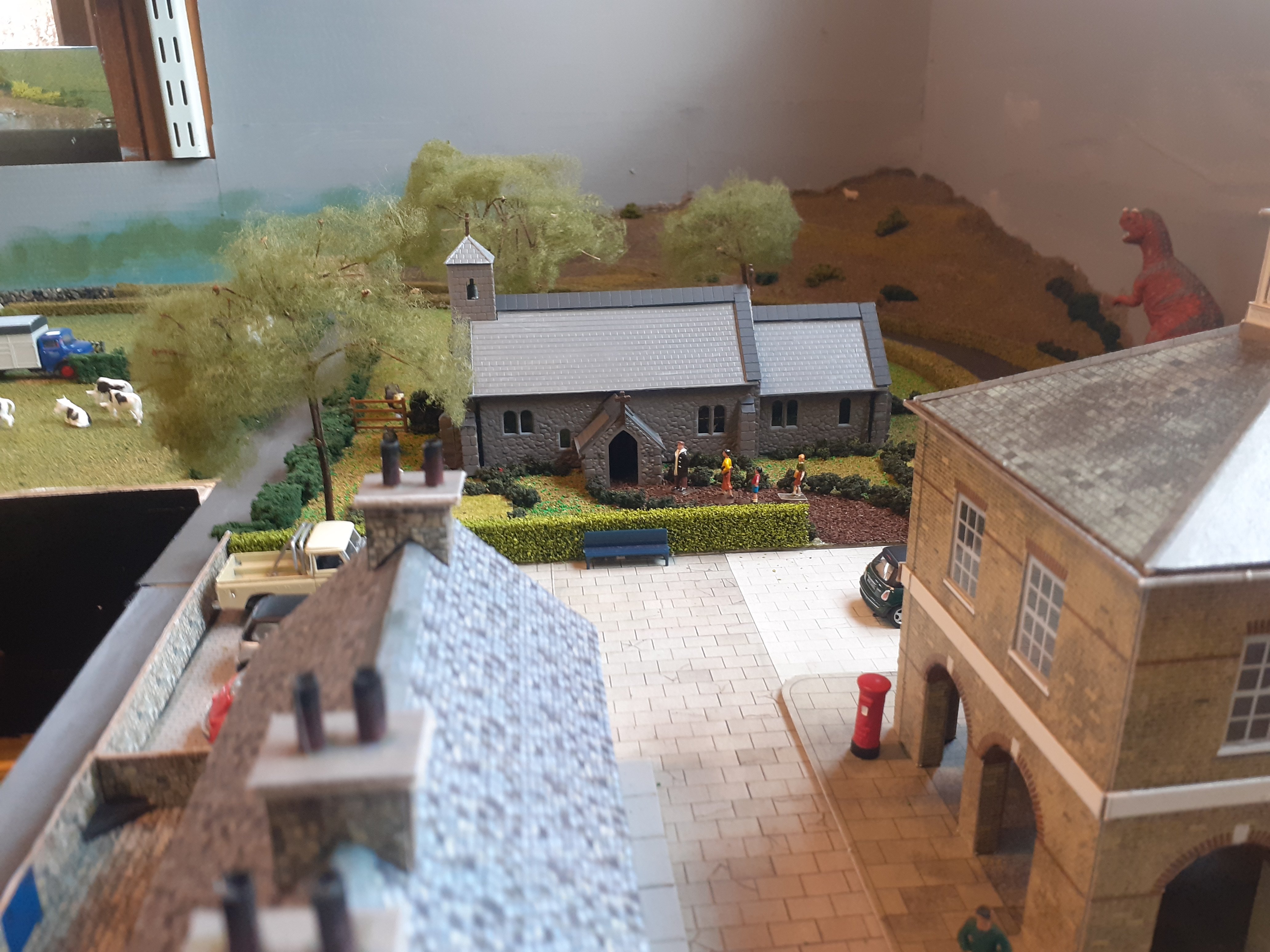
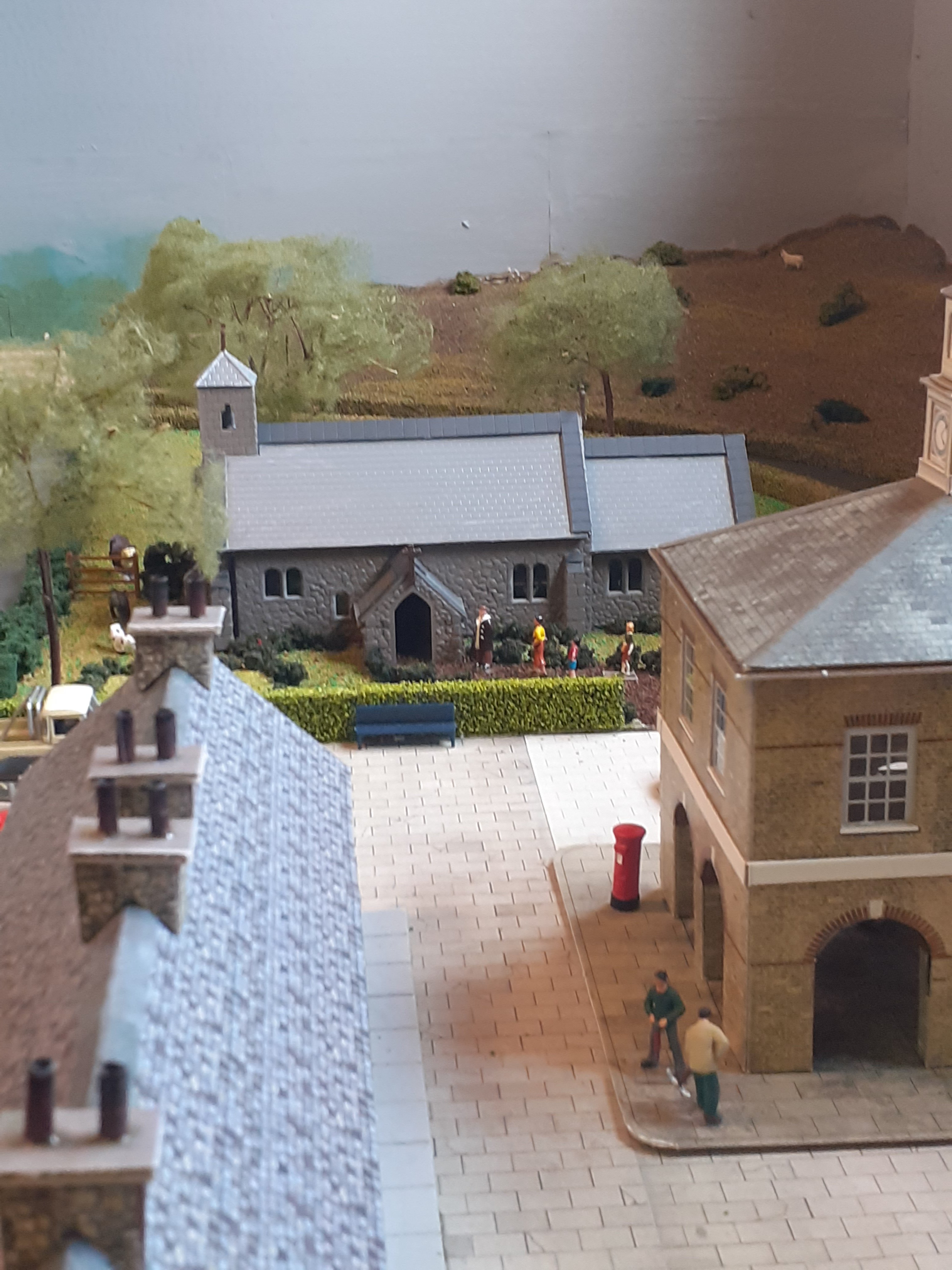
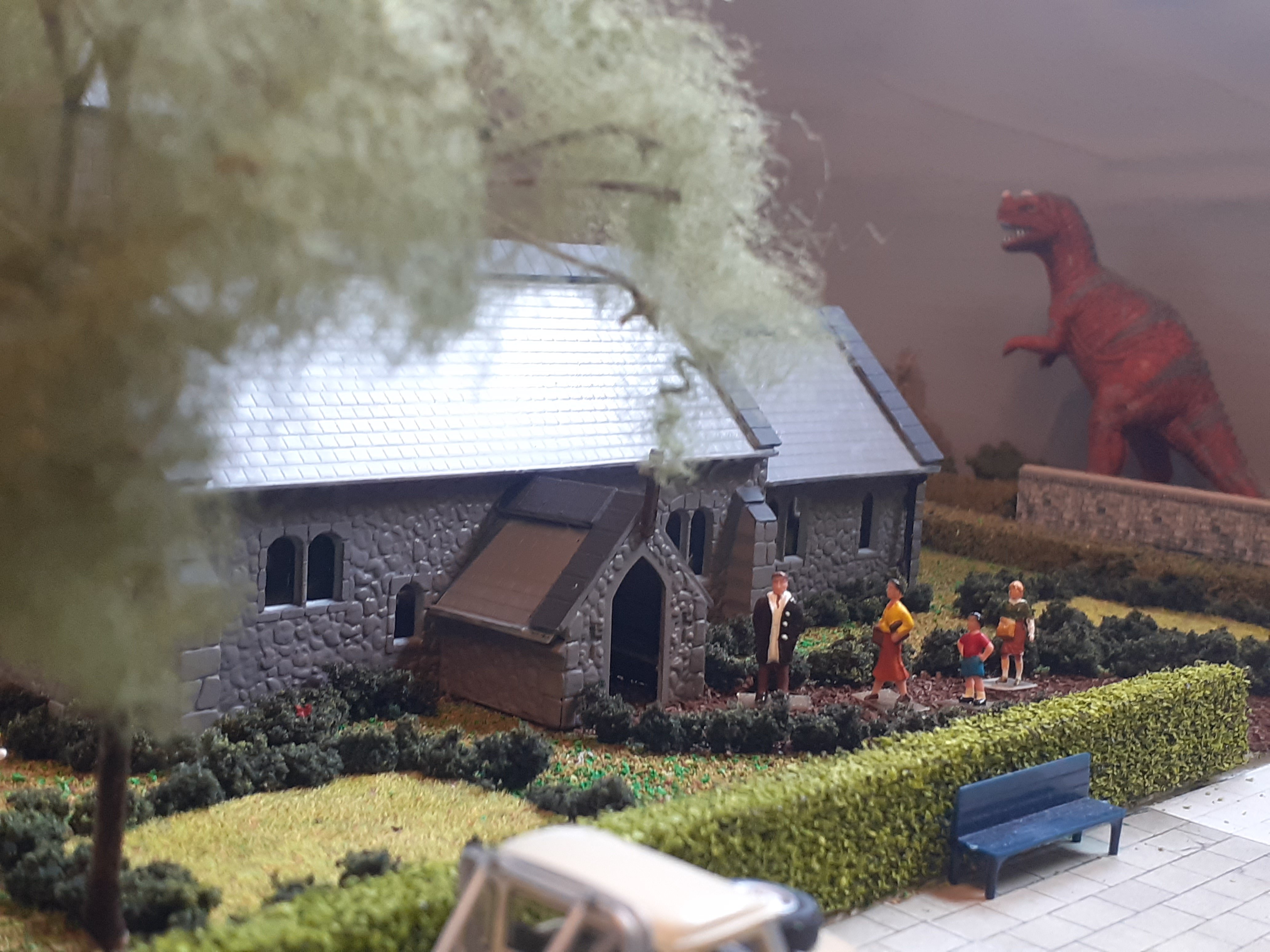
Thanks guys for likes and comments, the T Rex just keeps popping up in my photos!!!!, a bit like the elf on the shelf. What i love about our hobby is we can create a "world" and its our story. Some of you might get a kick out of this video story i made......not quite the right time of year, but what the hay.
-
sorry might seem confusing what i'm doing just re did the photos and deleted old ones
-
And the after video After.mp4
-
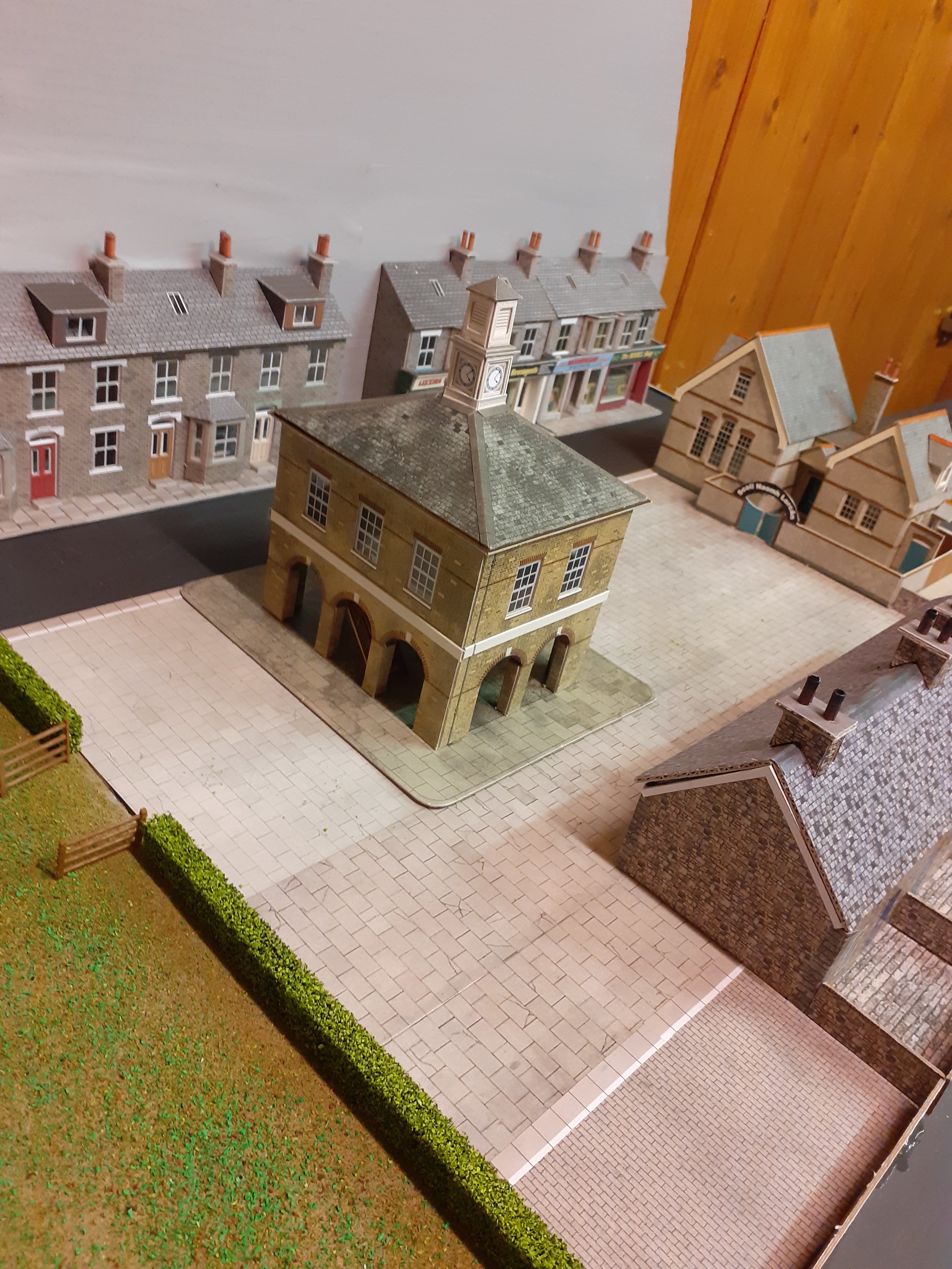
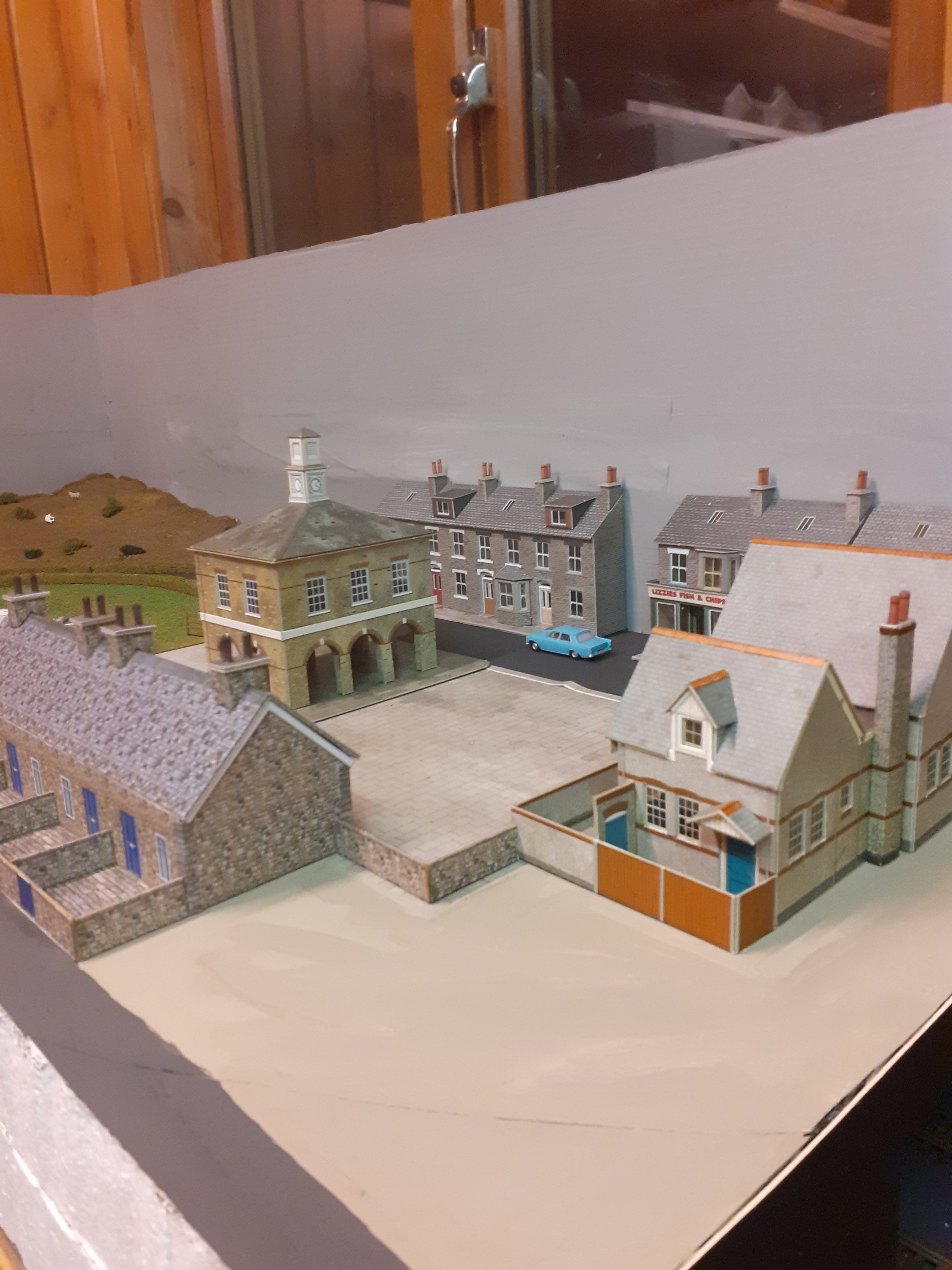
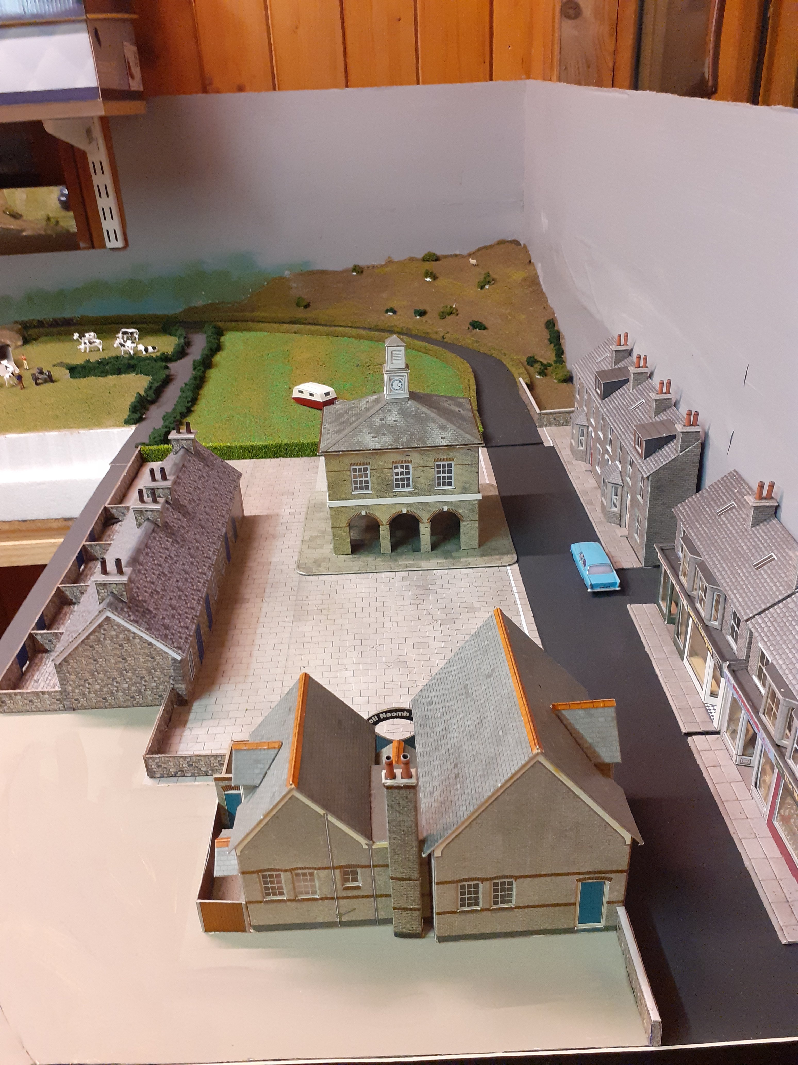
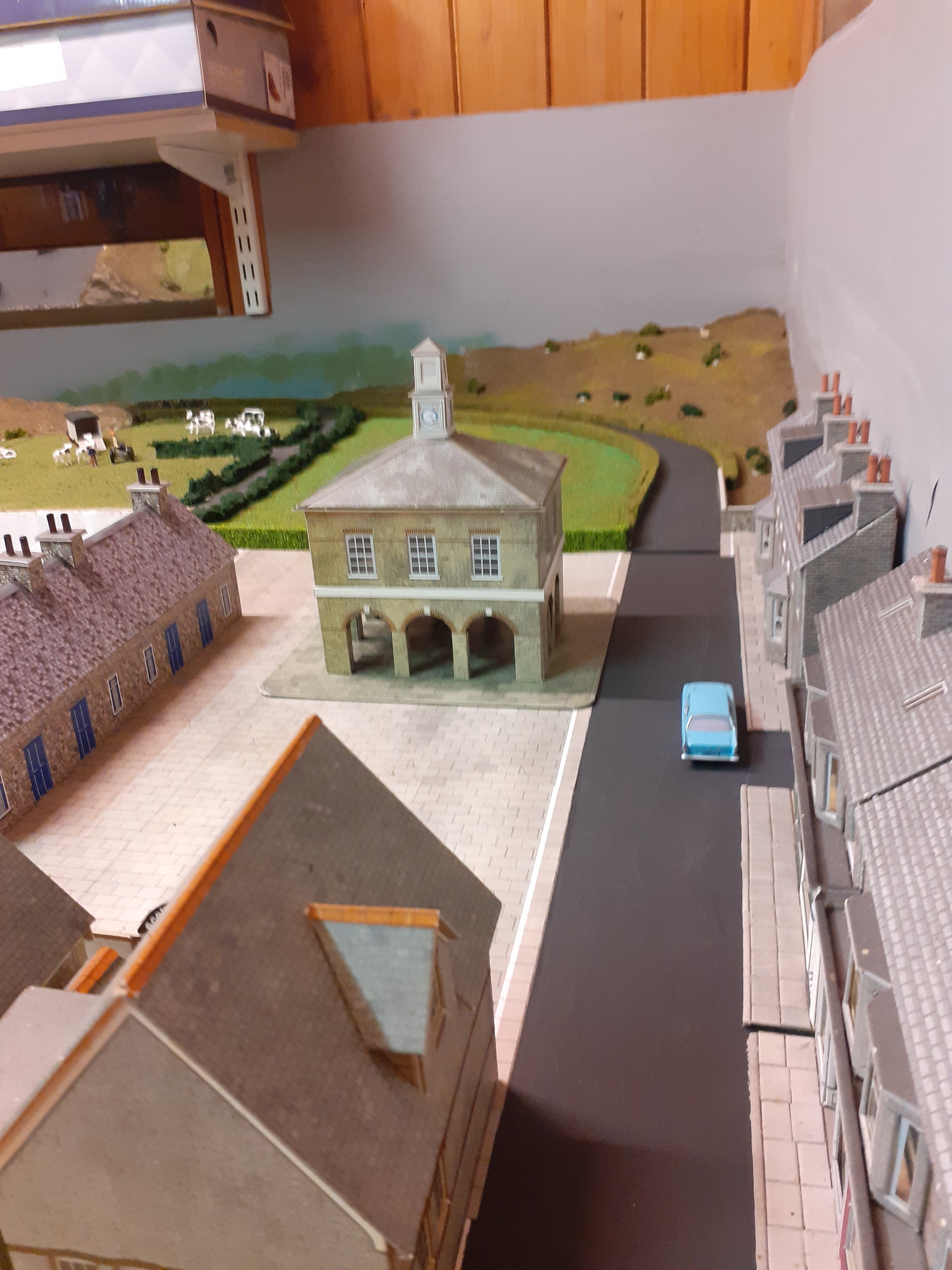
Some ground cover done, ballasting and Dapol church added to town scene. Before and after Videos to illustrate and some photos. Before.mp4
-
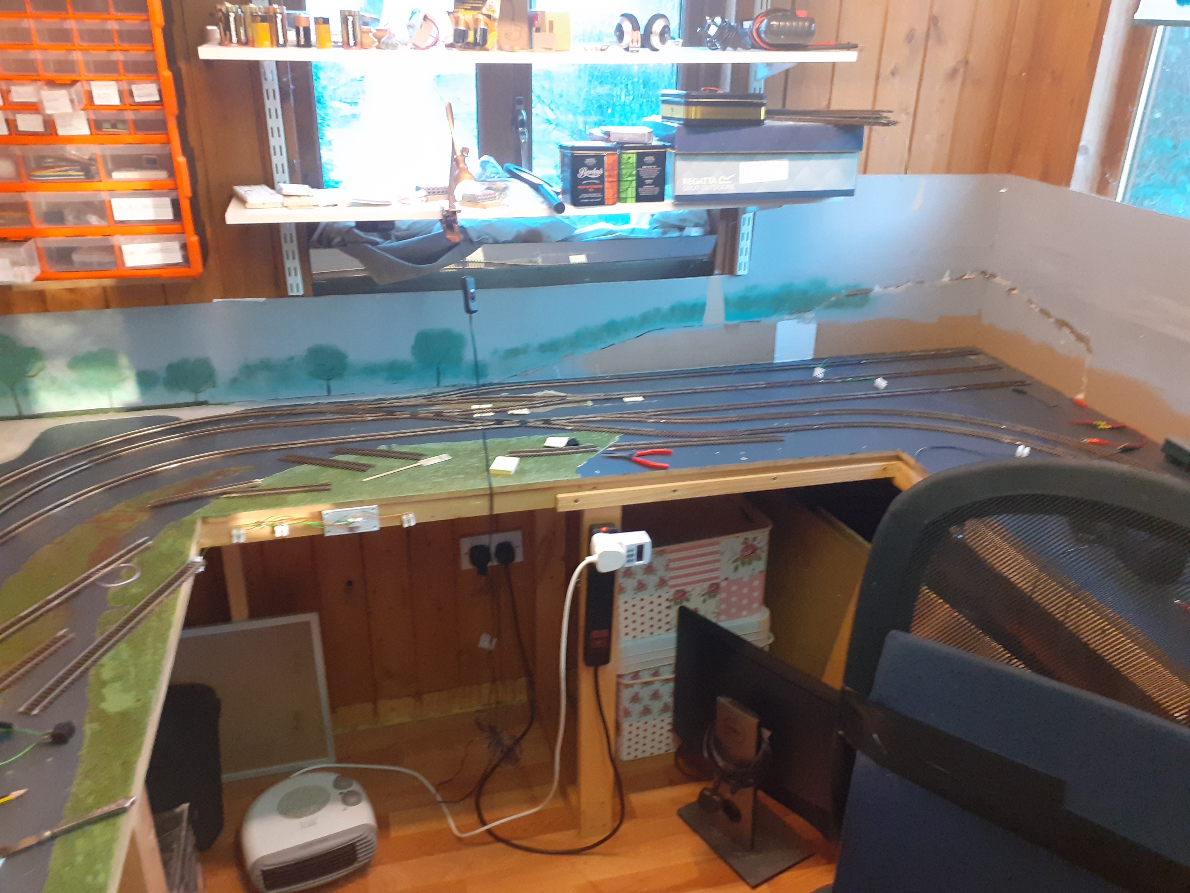
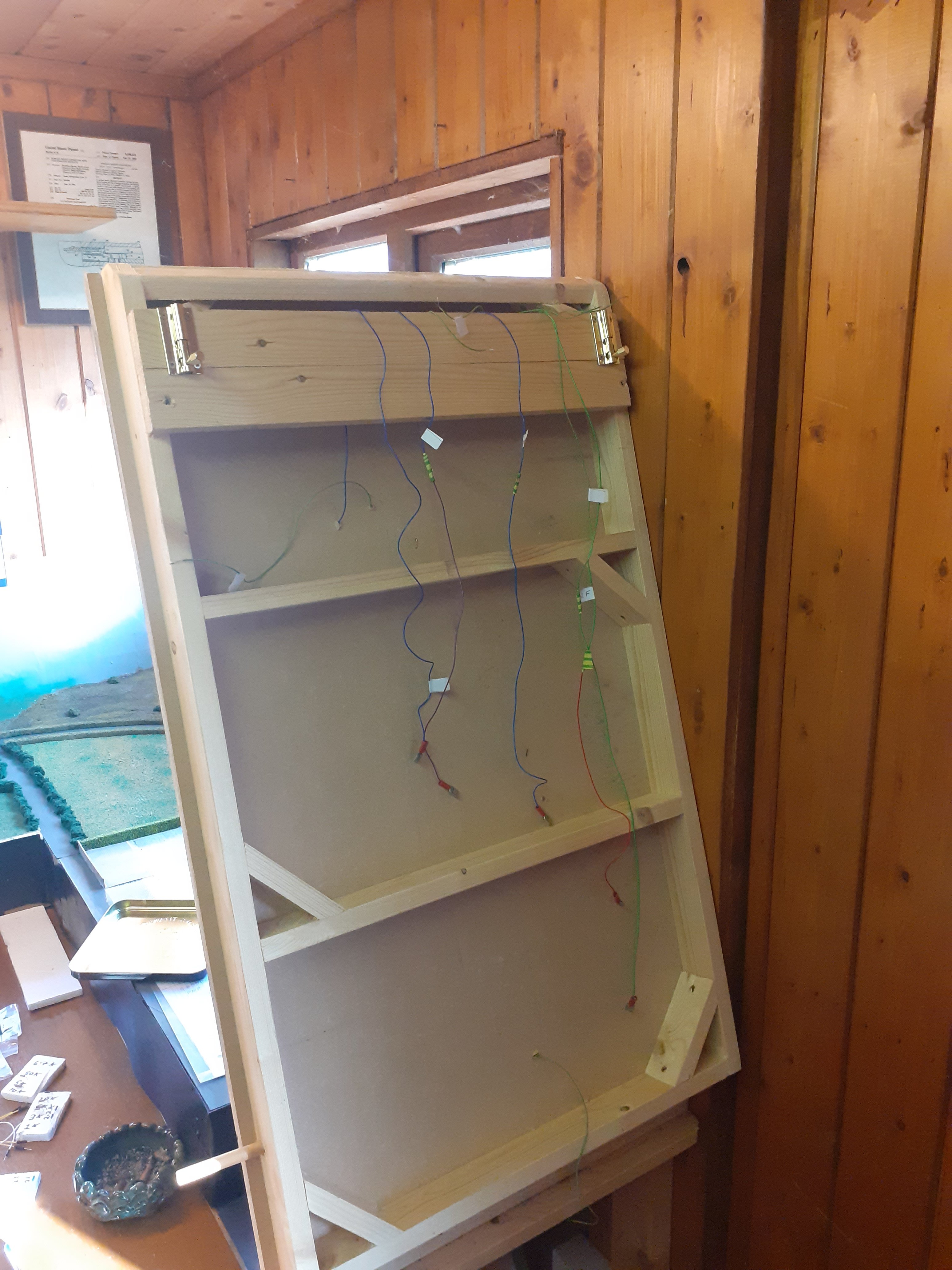
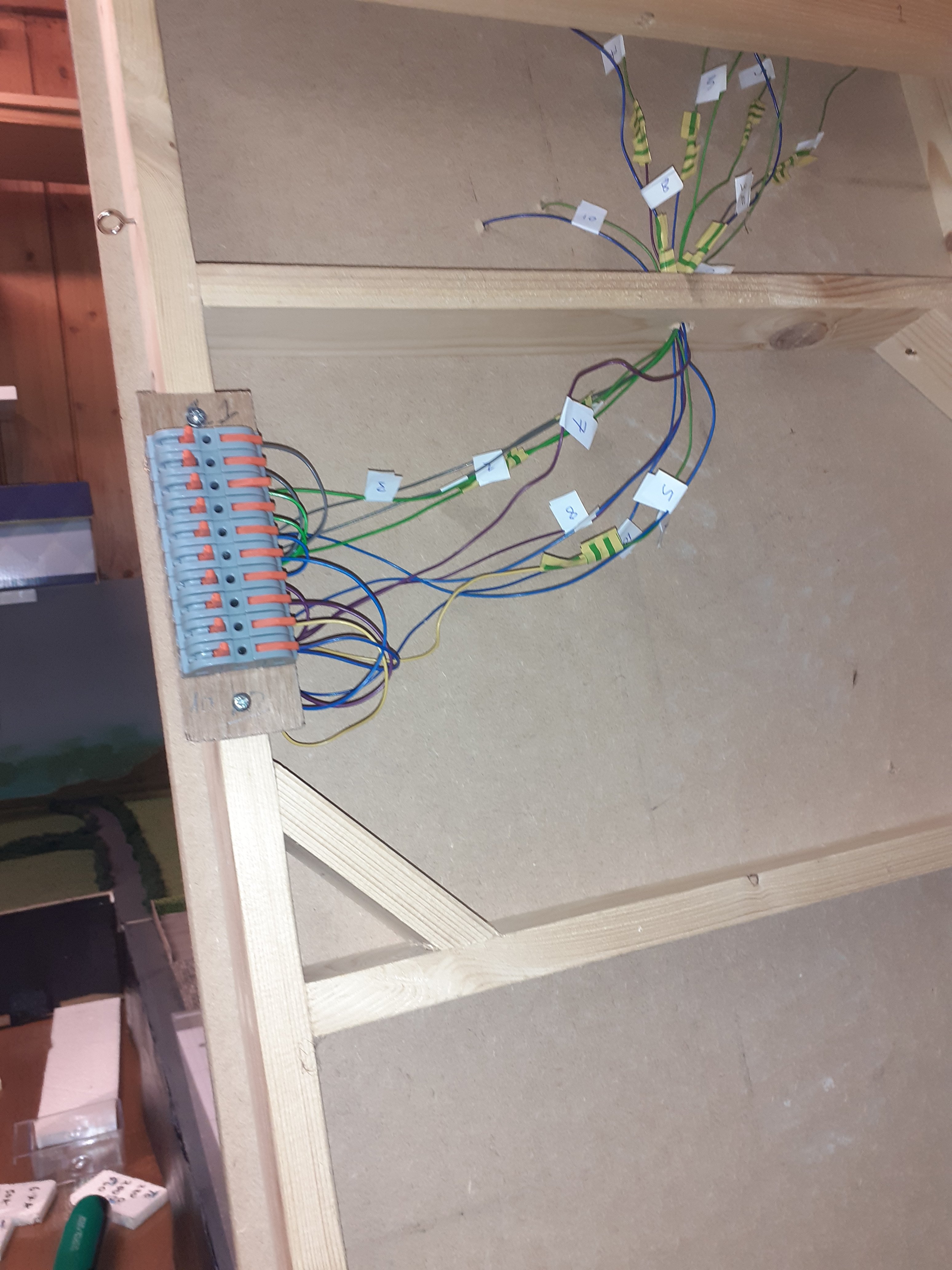
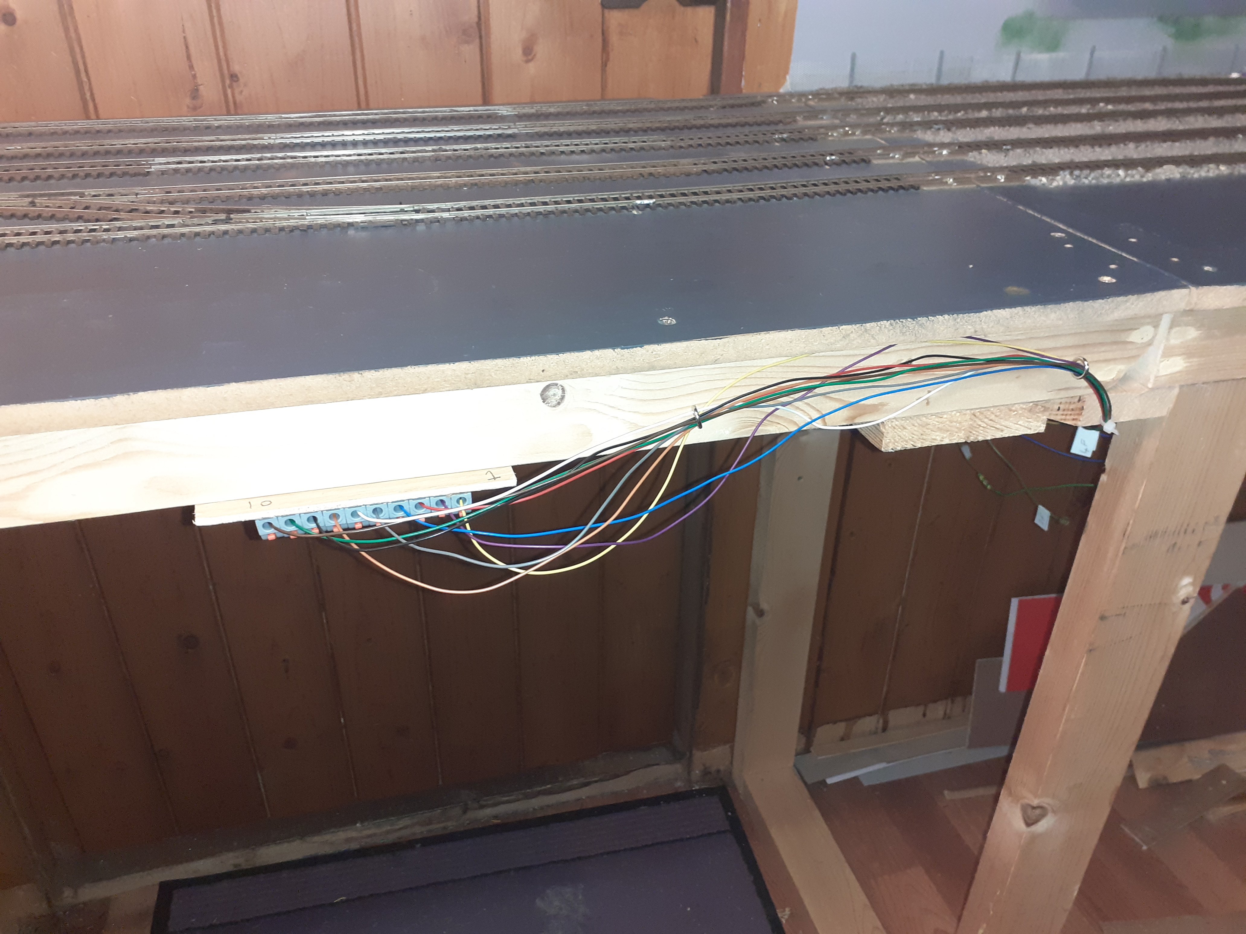
Quite a long break since my last post. I usually work on the layout during the dark winter evenings. However, this “season” I had a knee joint replacement in late november, so not too much done, until the past few weeks. One job that I’d been putting off, became a necessity. I always used to crawl under the lifting flap at the door, the wiring was a mess, see photo, and reconnecting all 10 wires across the gap was not an easy job. But with the knee, my crawling days are over in the medium term, so I had to come up with a solution so that I could run trains. I got some quick release connectors on amazon and set to work. Number all the wires and even coloured coded them. It works and just takes a couple of minutes to connect up. More updates to follow.
-
yeah the tank is one of those airfix kits you get in lidl every so often, i've a spitfire hanging from the ceiling, i think we all cut our teeth making those kits, saving up the old pocket money. I used to do dioramas with tanks and the soldiers. So i got a pack of 1/72 scale soldiers and might paint them up next winter and was thinking of doing a battle scene in the village.... not so sure about it now with a real war unfolding in front of us, seems a bit tasteless.
-
Video tour around the layout.
-
Thanks for all the wows and likes, any questions feel free.
-
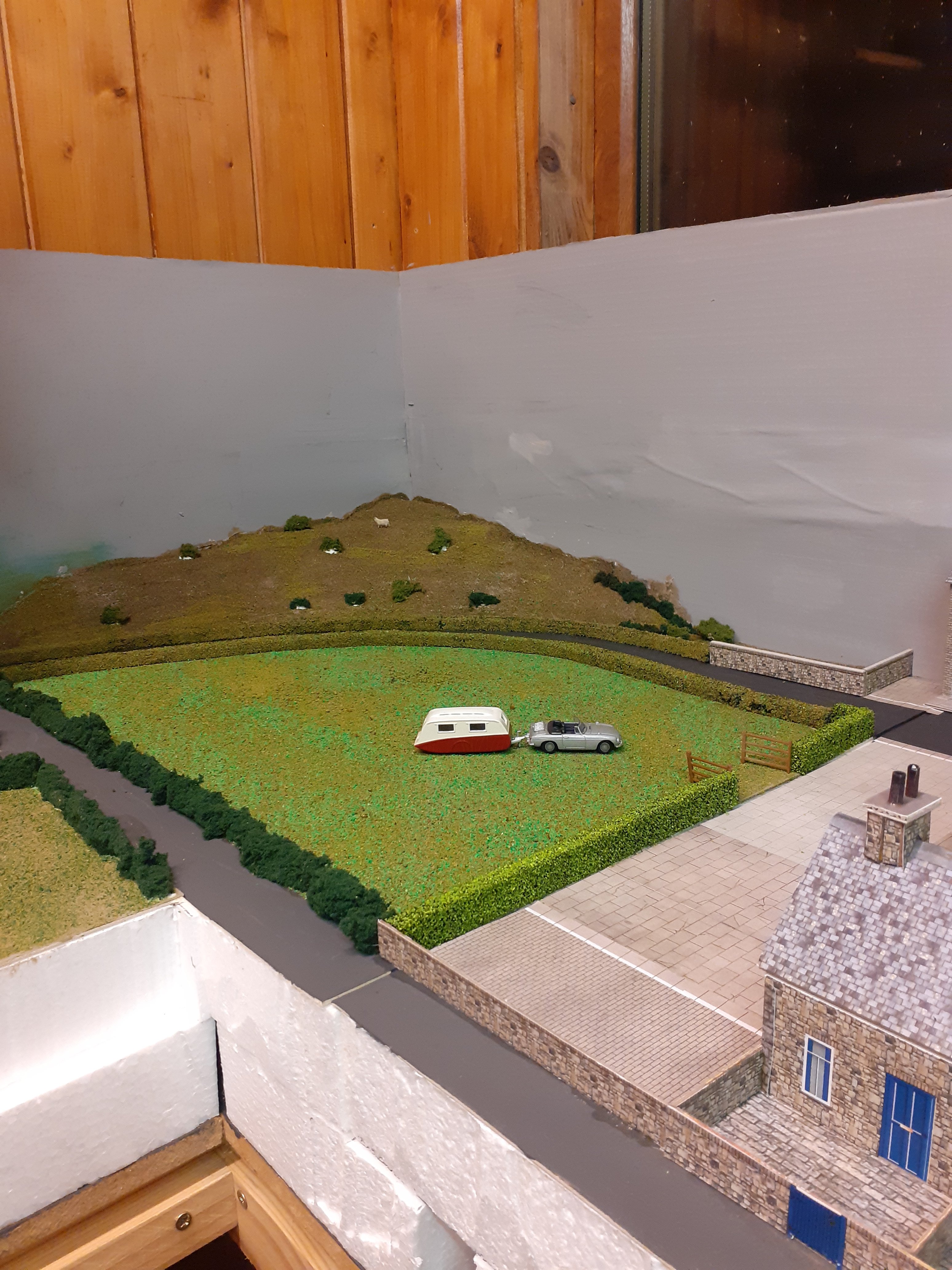
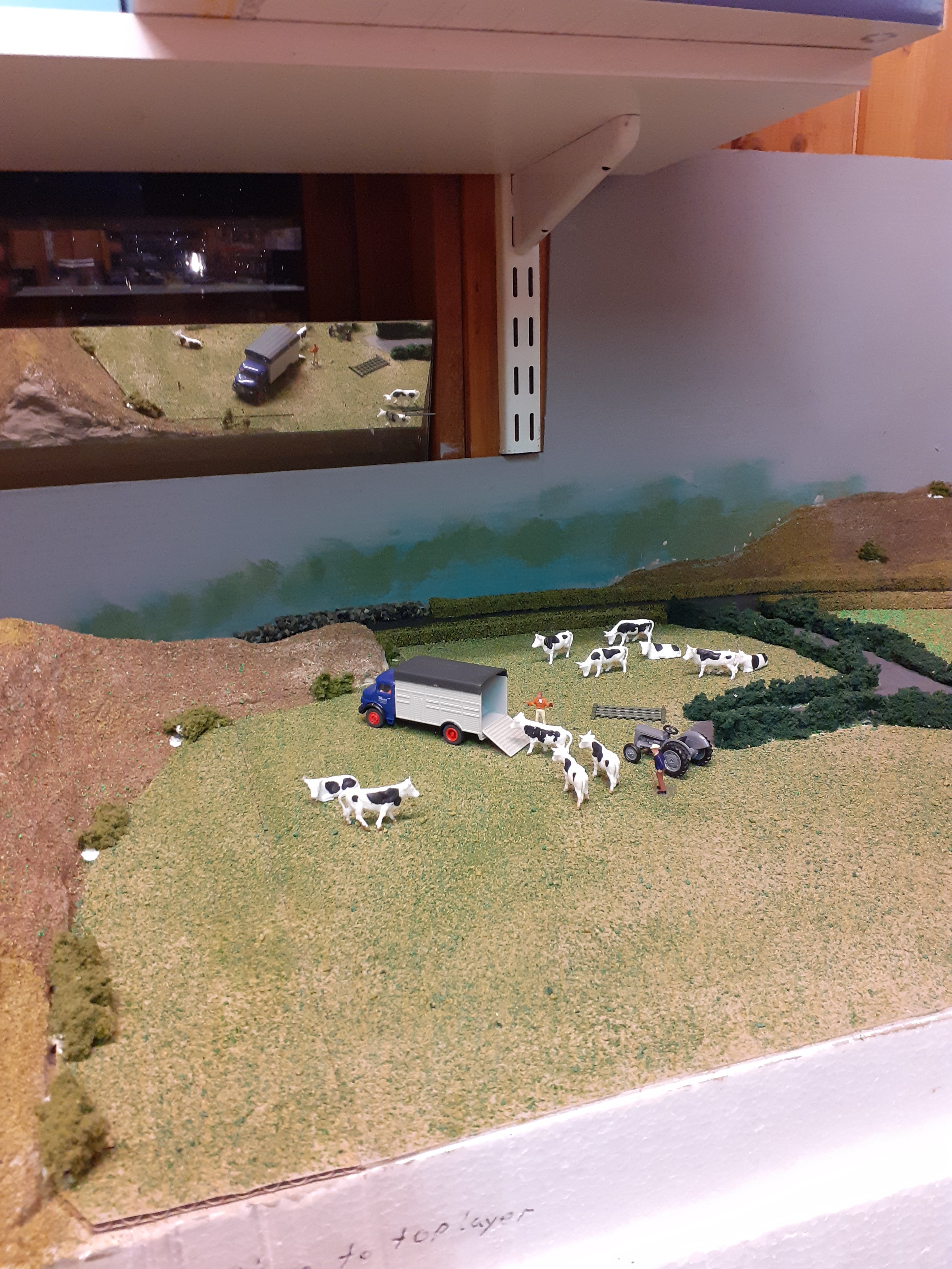
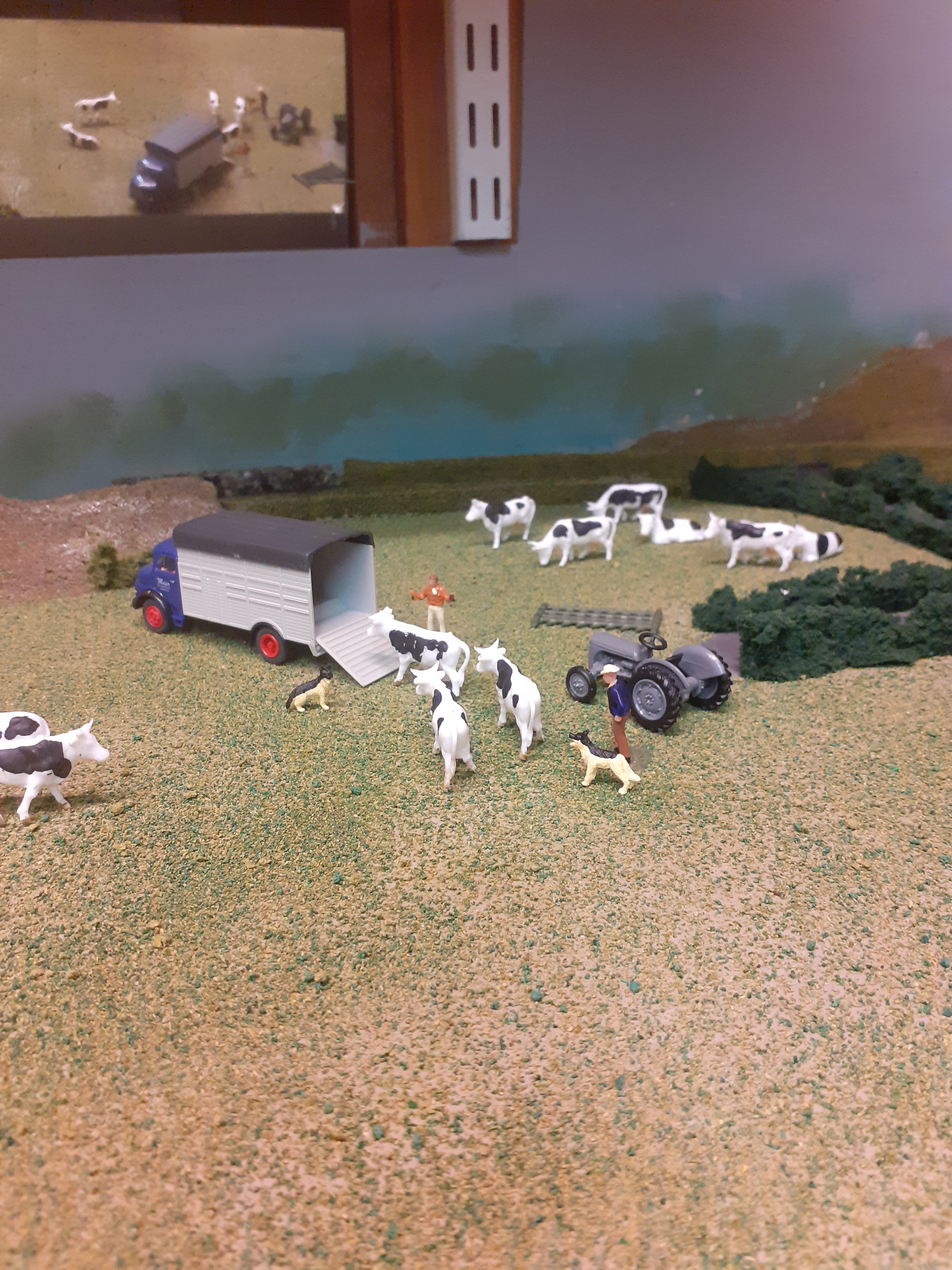
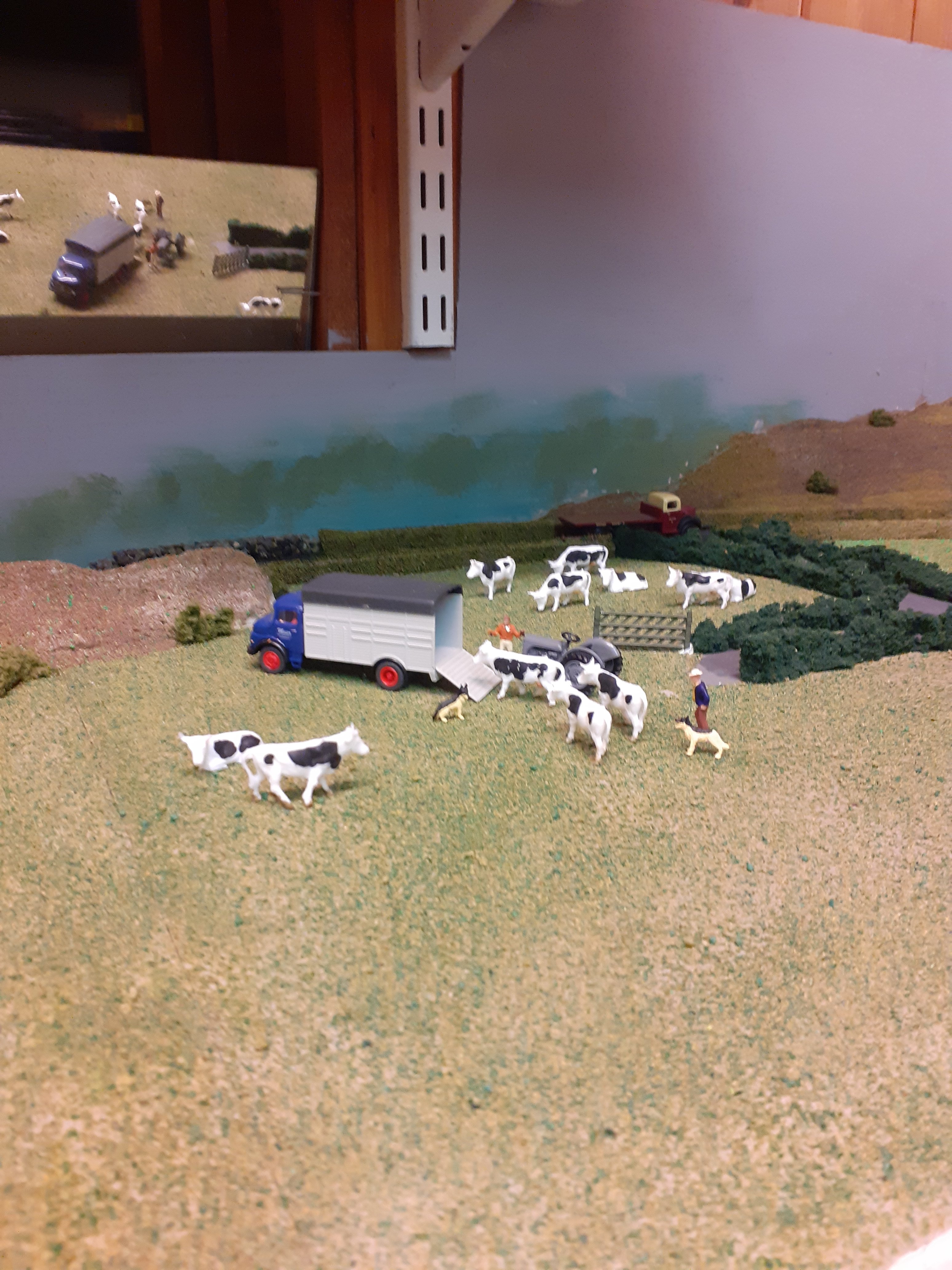
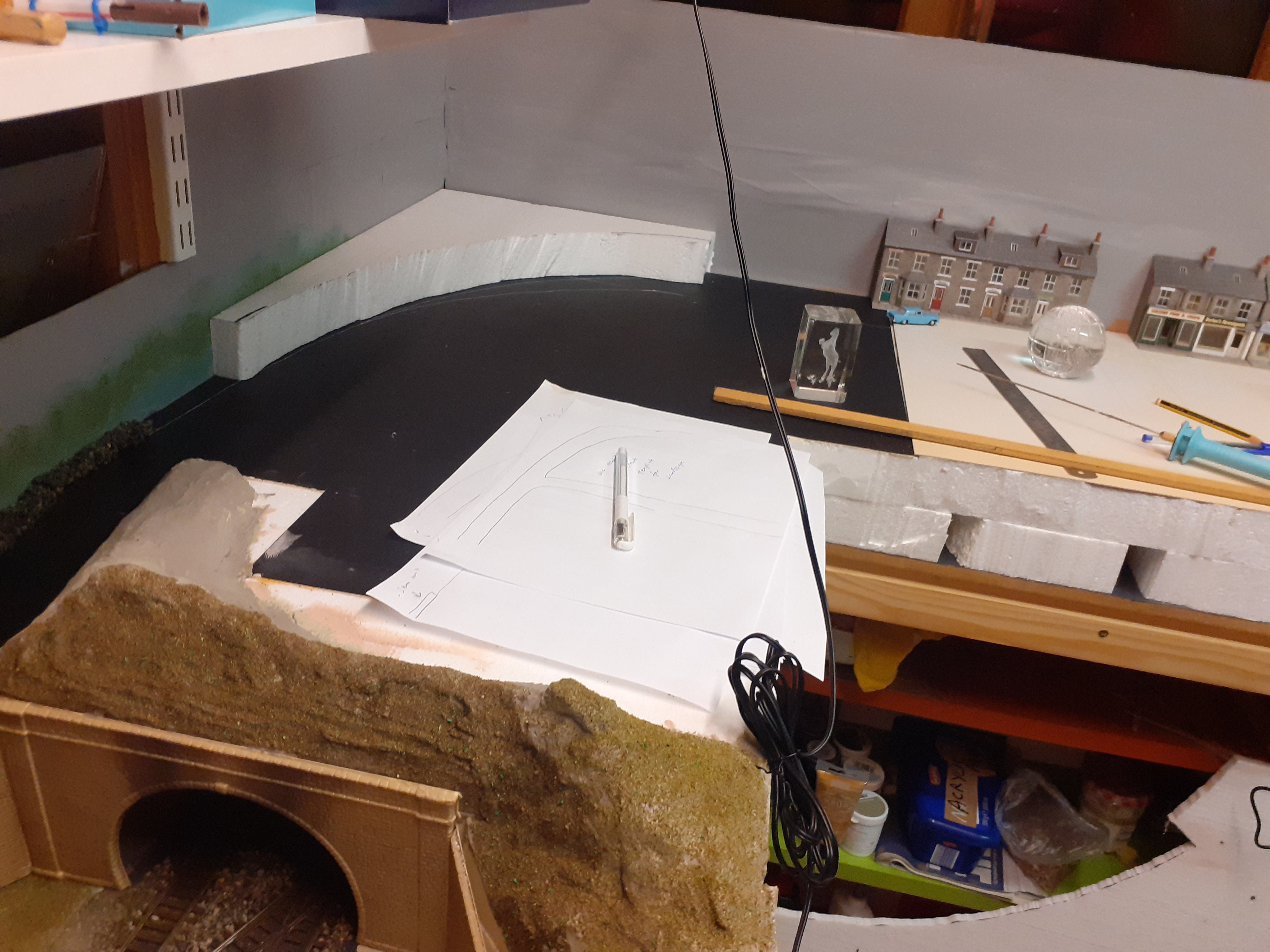
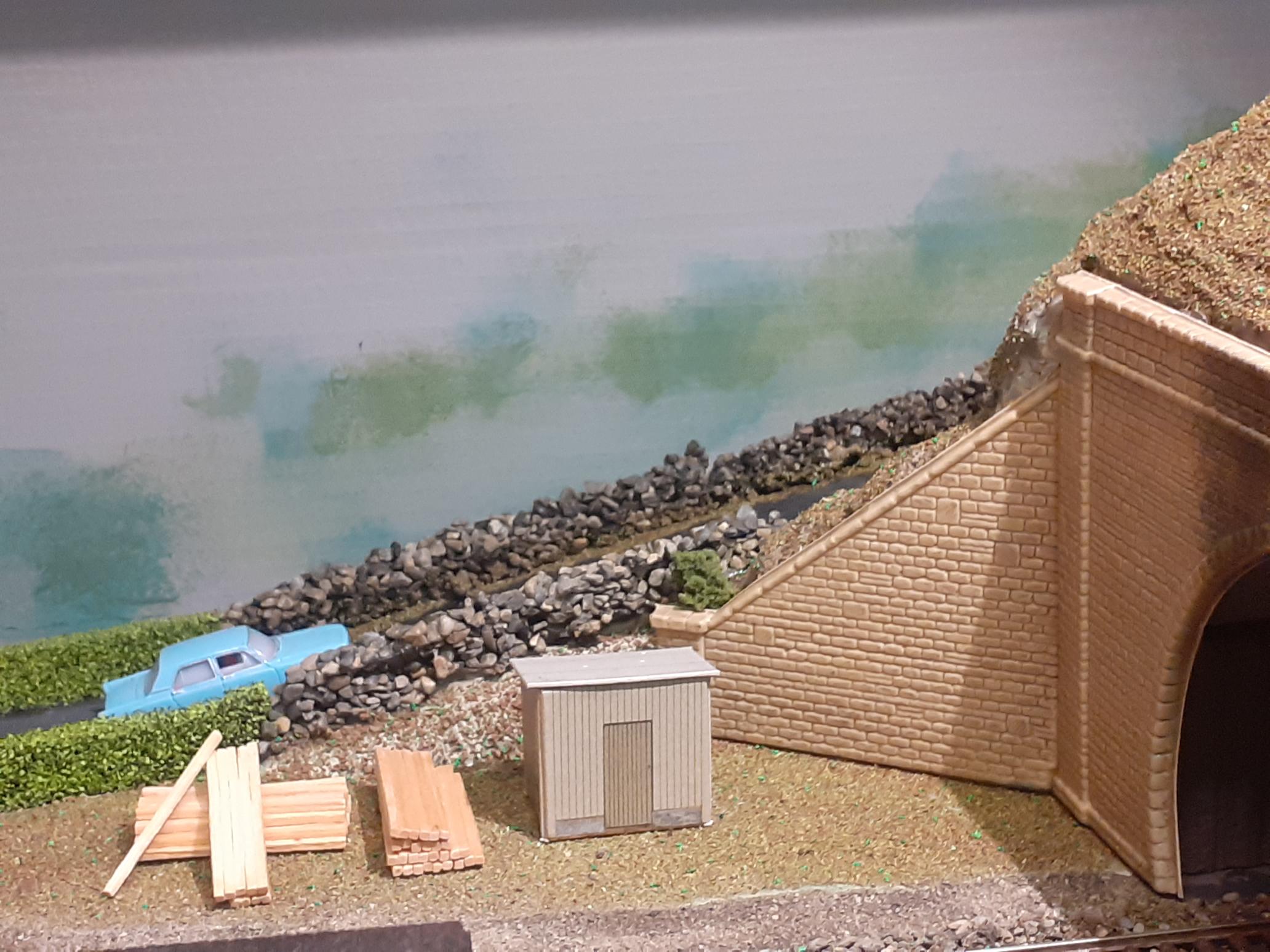
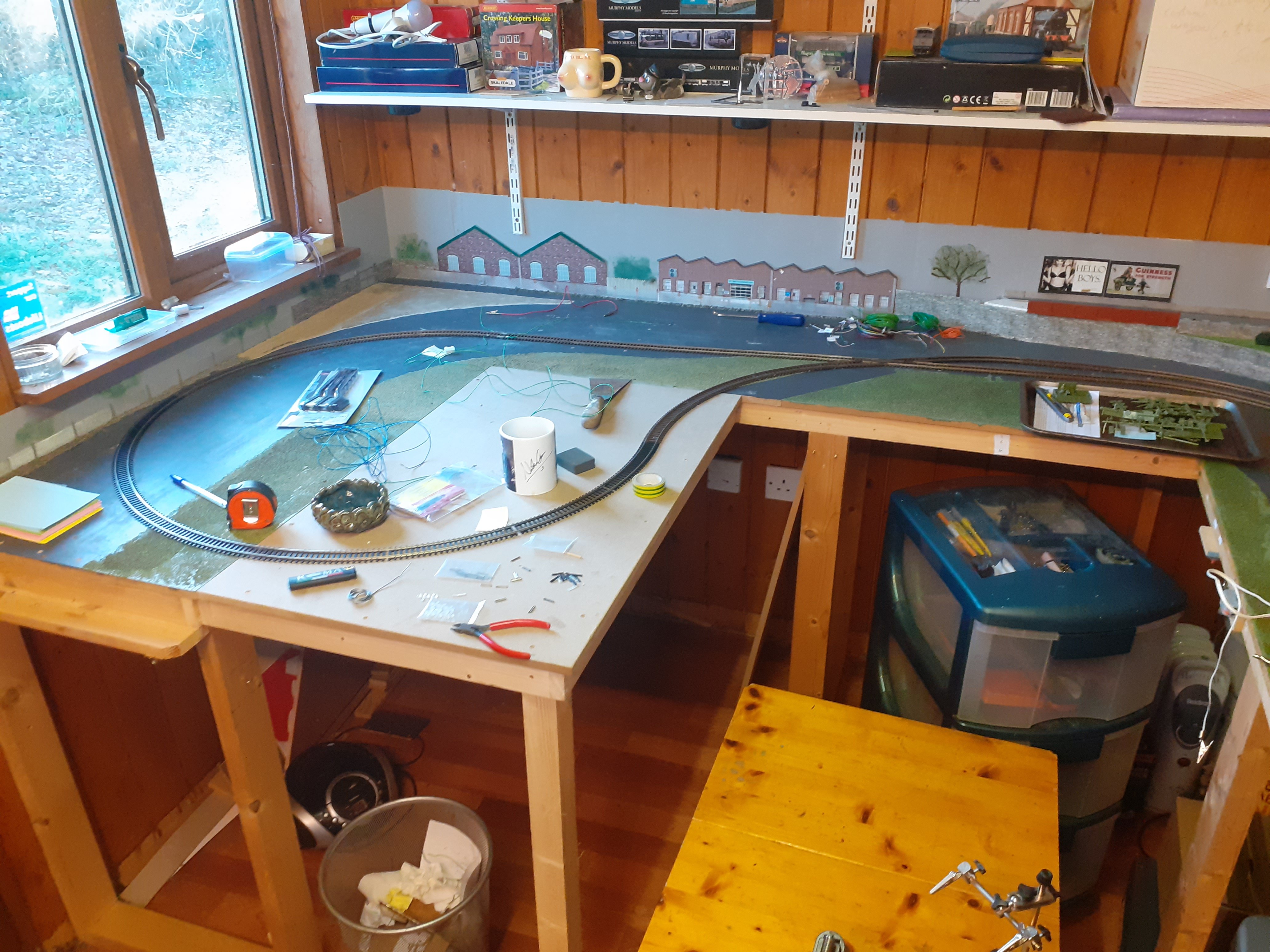
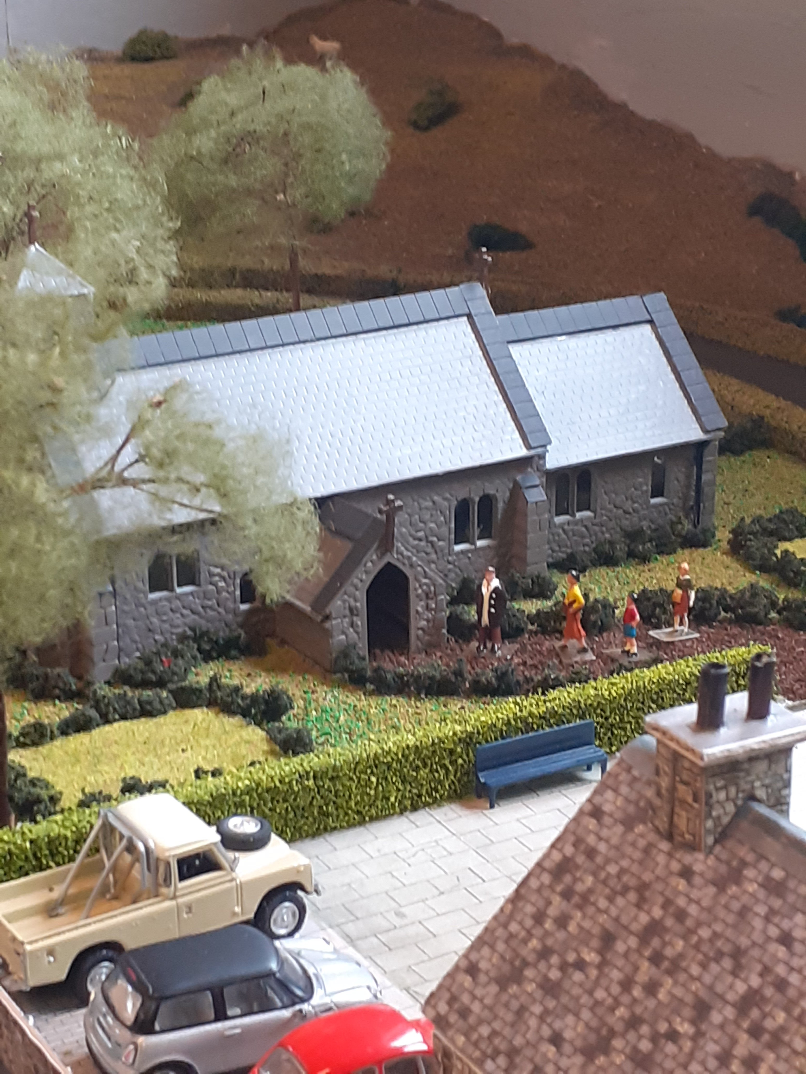
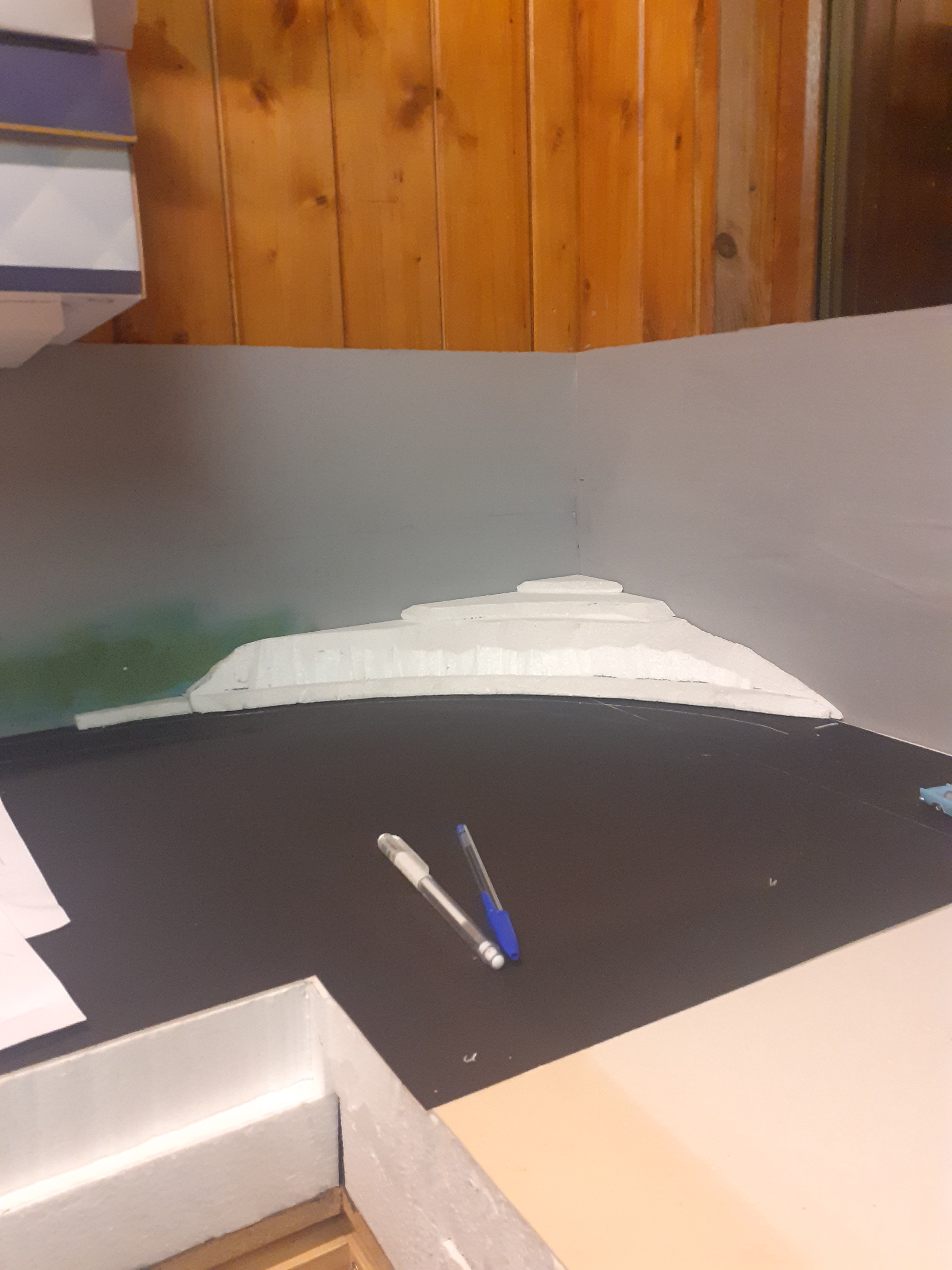
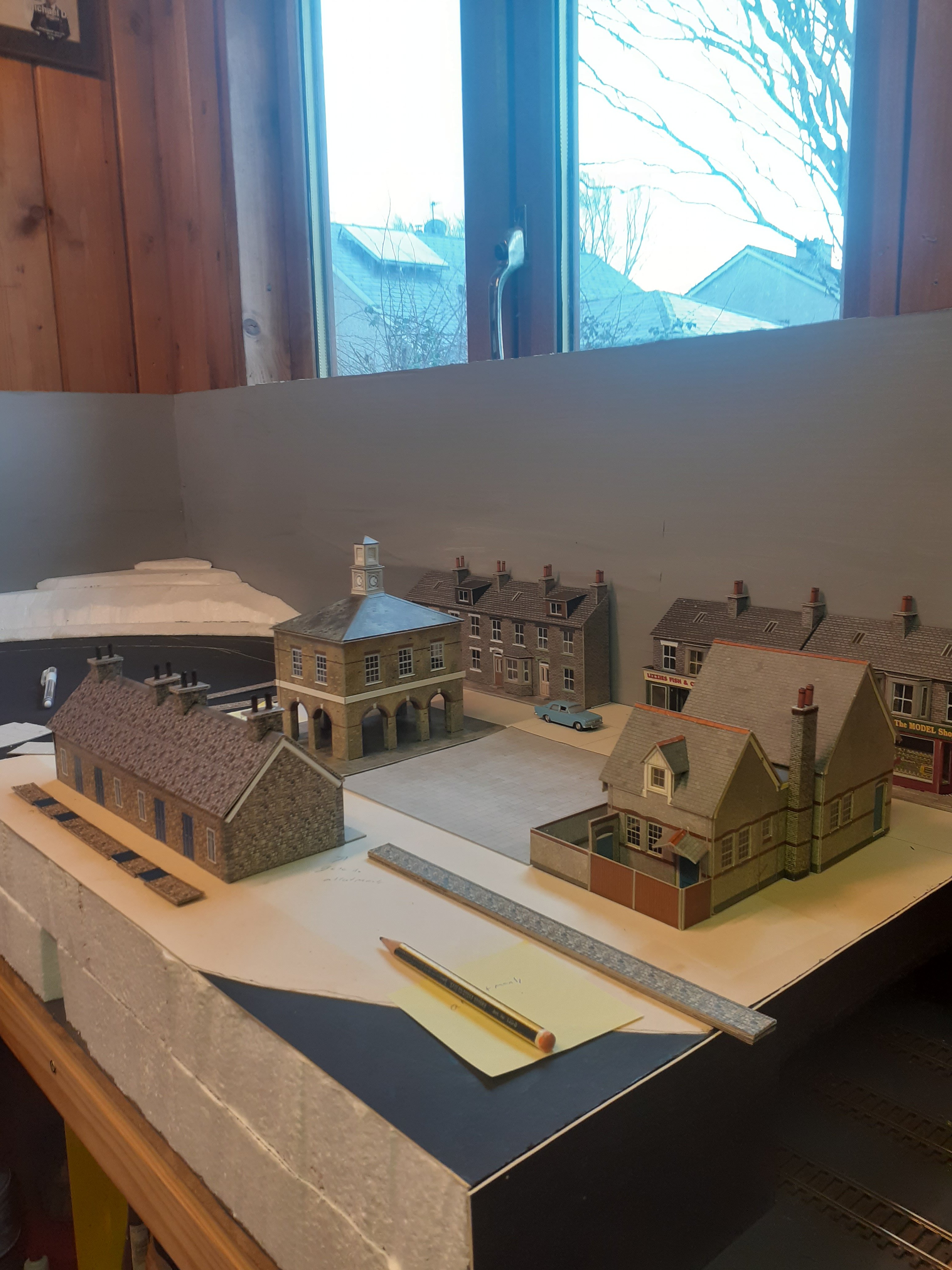
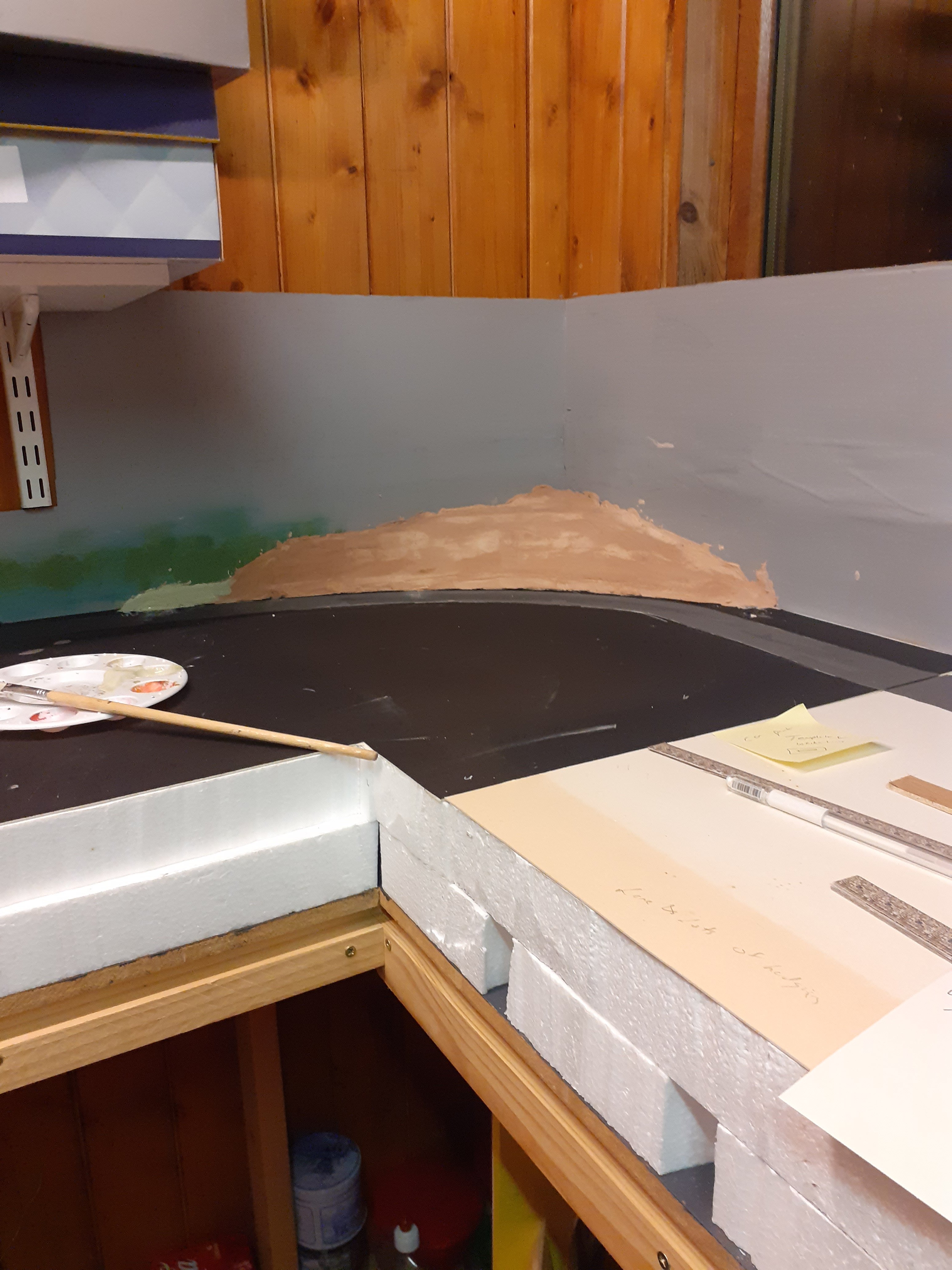
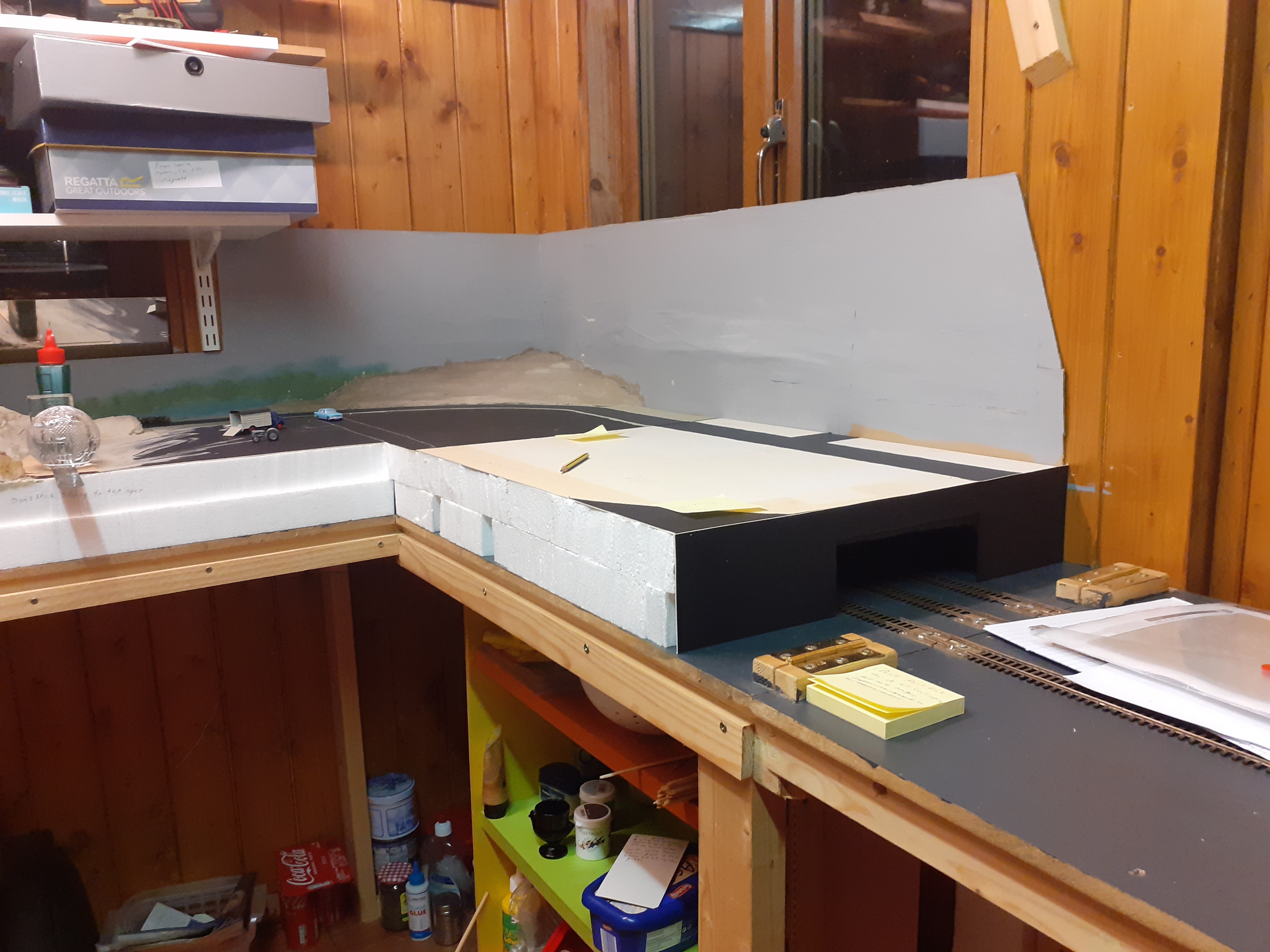
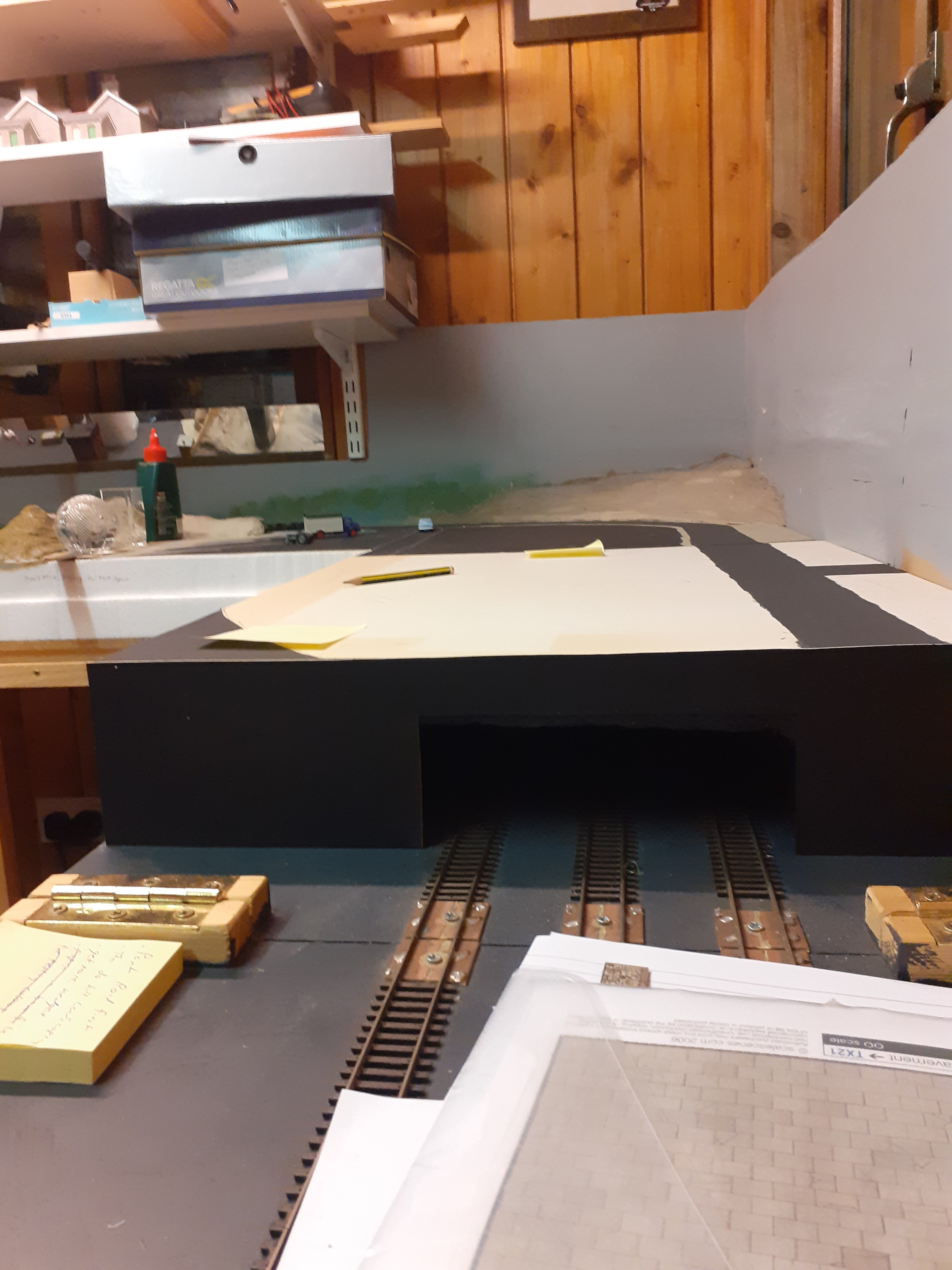
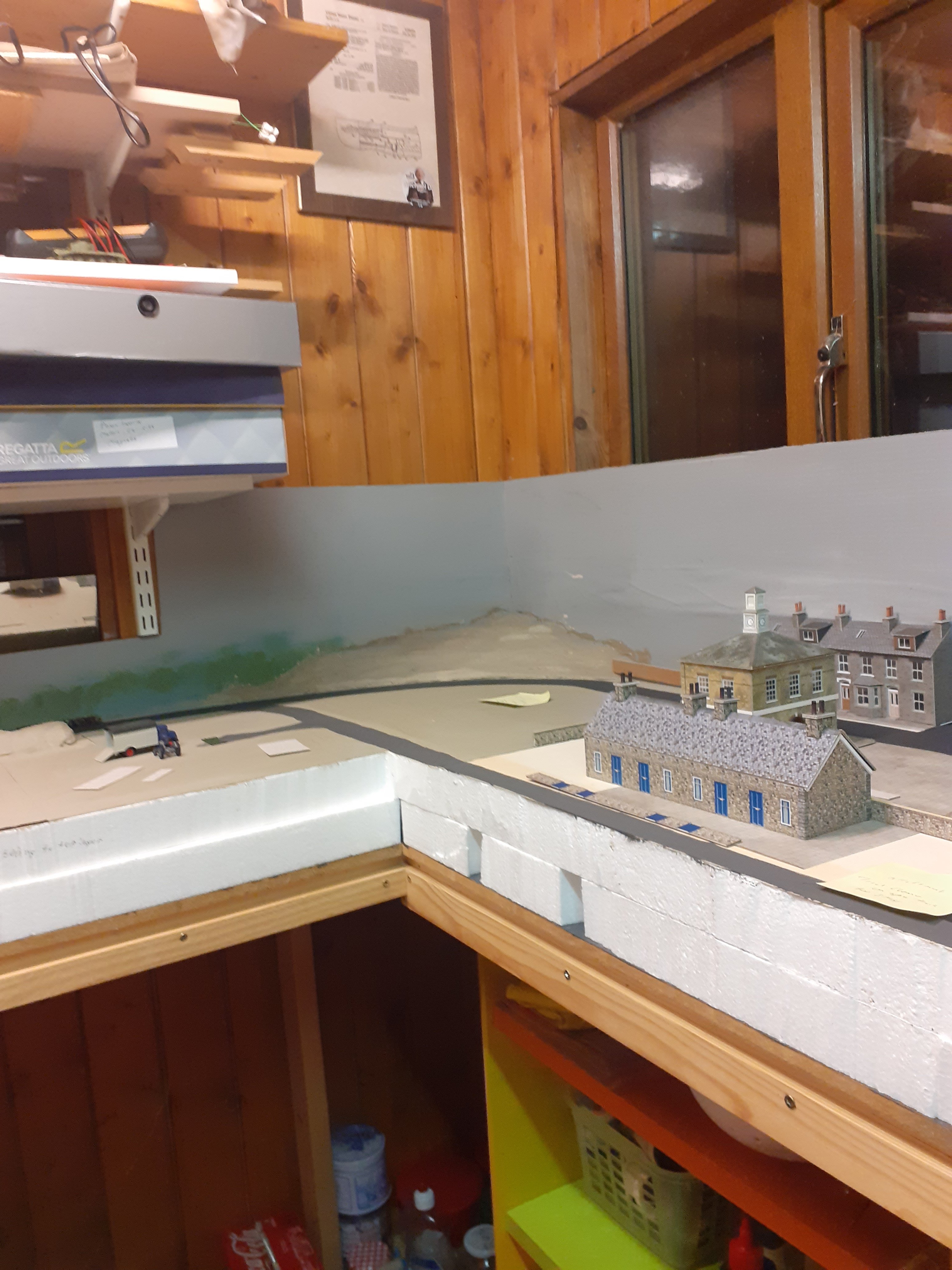
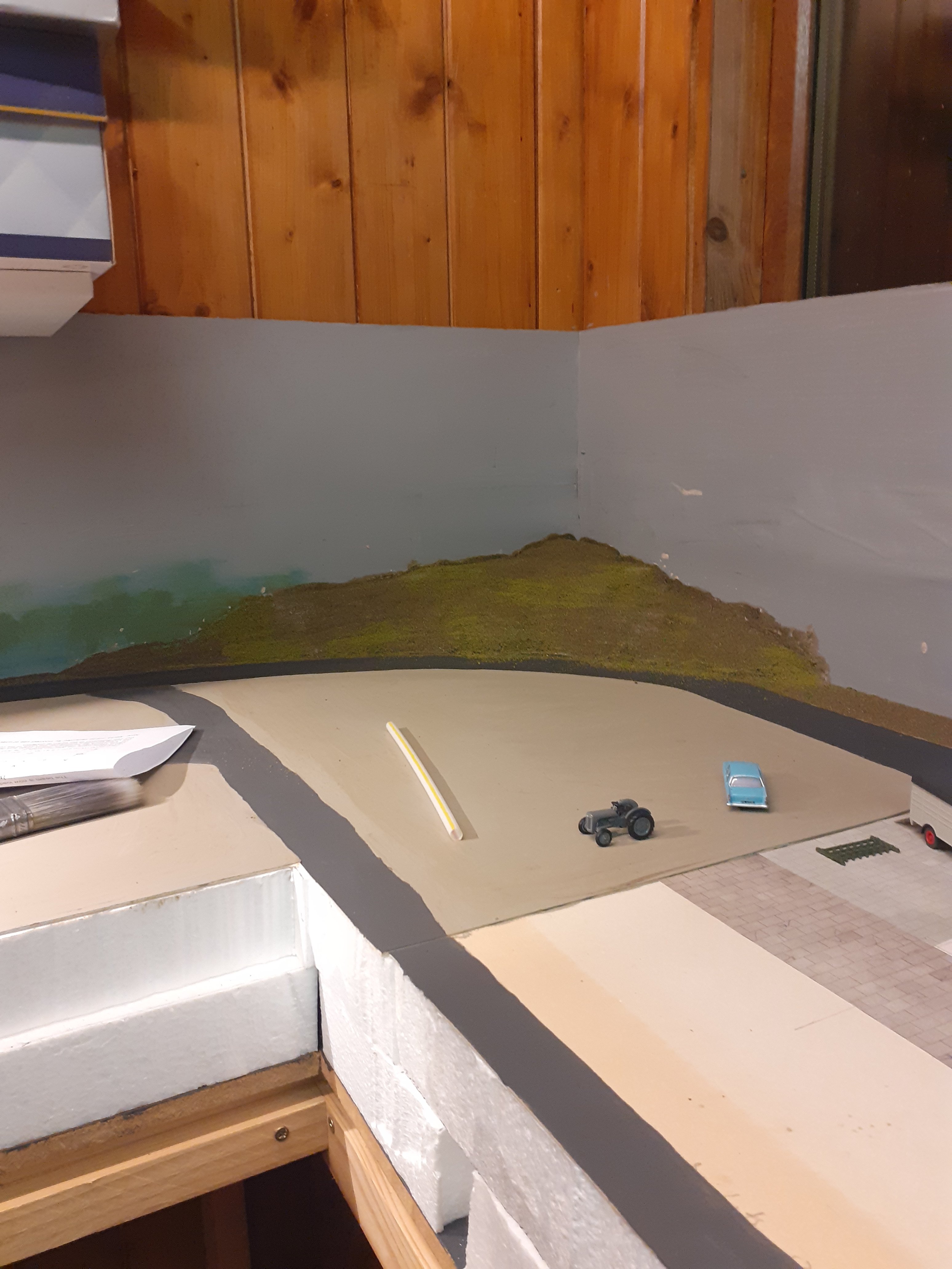
I added an elevated section to the remaining corner of the layout, so I have a tunnel which gives a scenic break. I used the area on top to create and town and country scene, I have been working on this since just after christmas. Lots of detailing still to do, but the core of the work is complete.
-
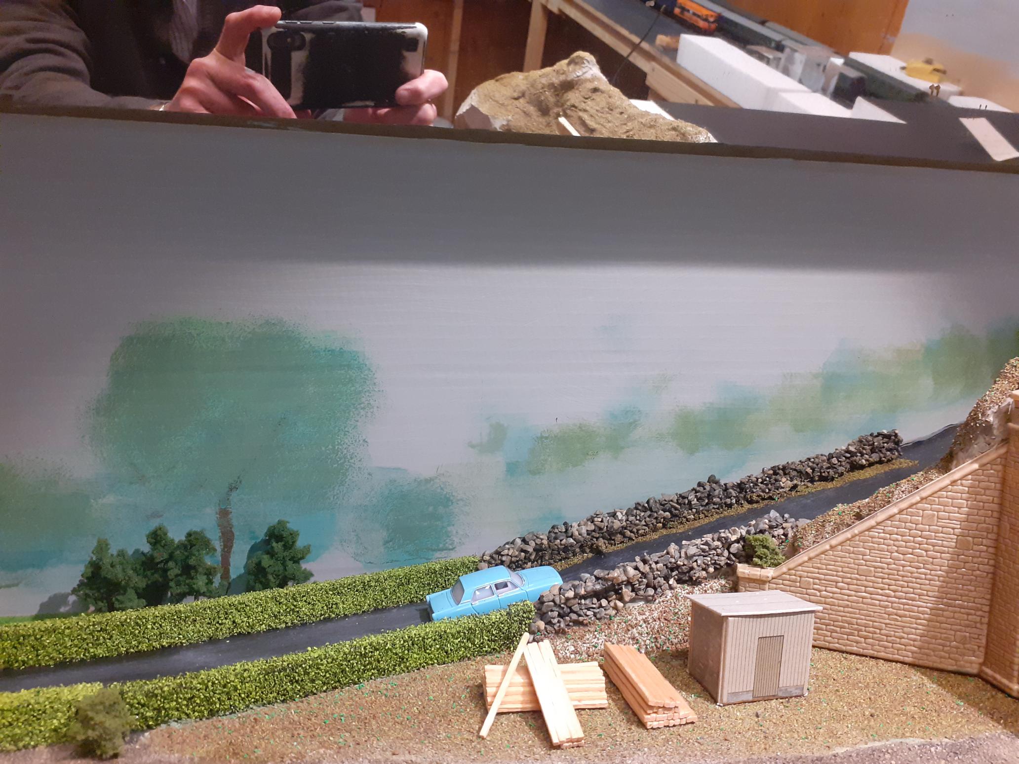
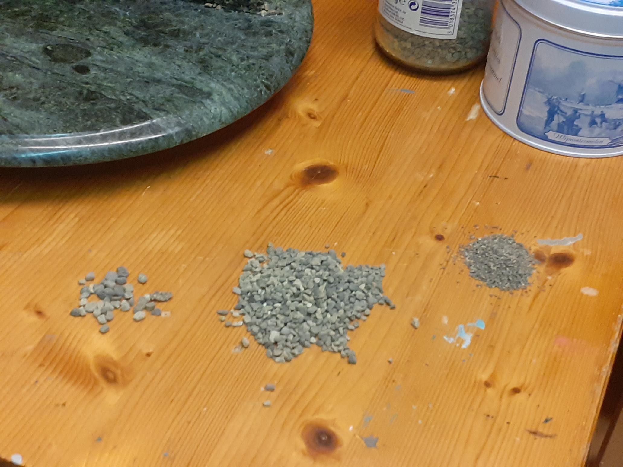
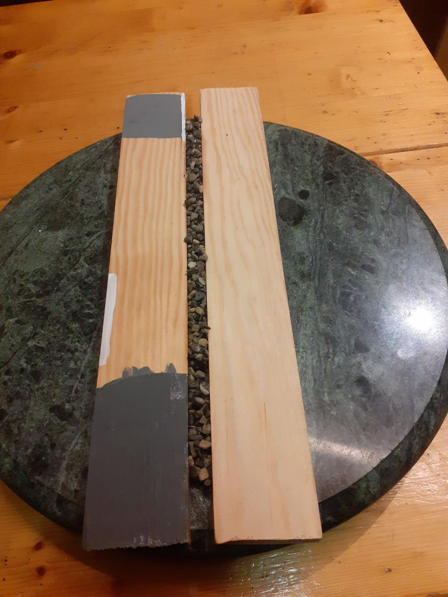
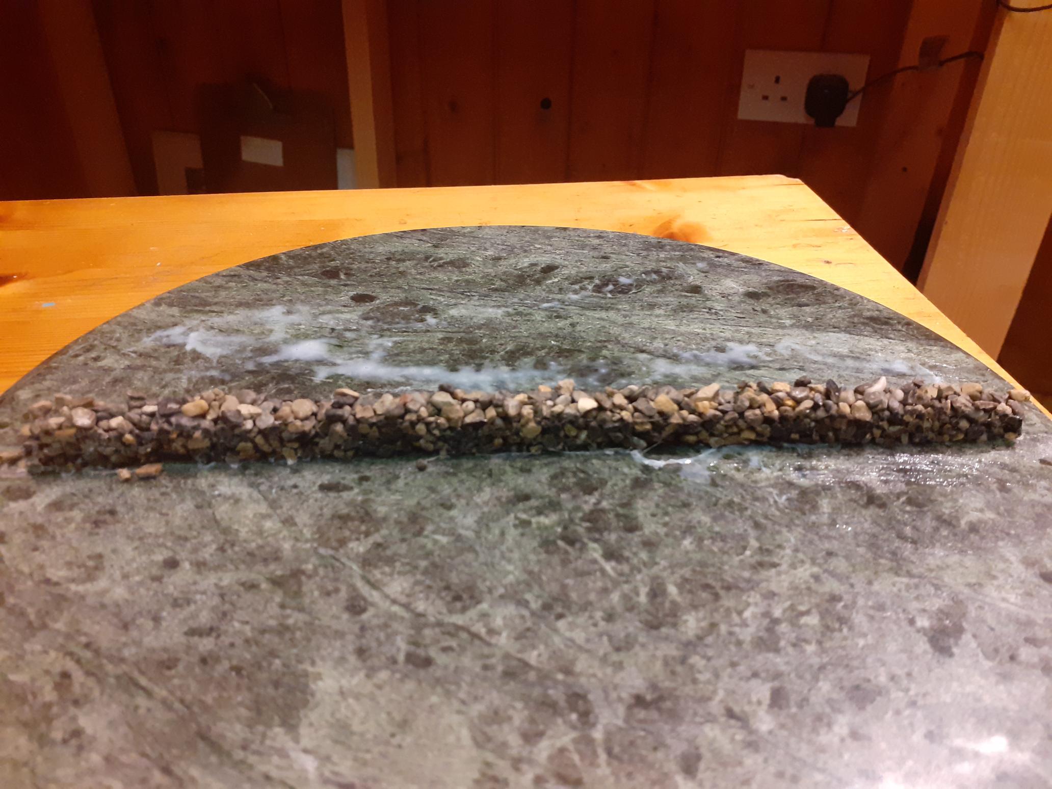
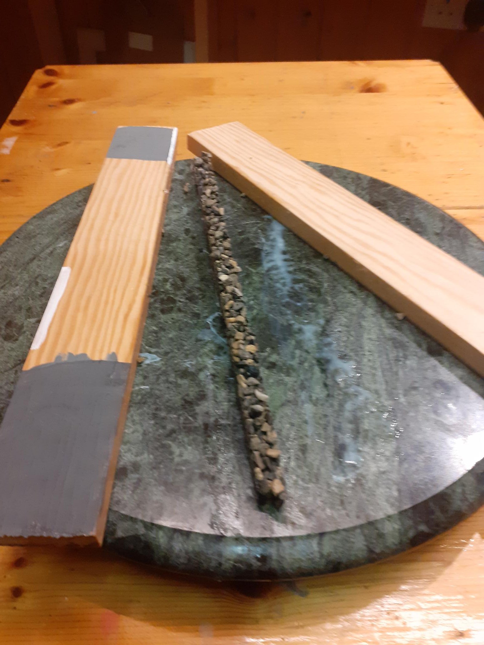
In case anyone is interested in how I made the wall along the ramp. I sieve normal builders sand into 3 grades. Larger pebbles for the wall, next for ballast along track and the finer stuff for general scatter between tracks. The wall is 15mm high by about 10mm deep. I make a mould with two pieces of wood. I smear a layer of vaseline on the wood and the ceramic base (learn’t this the hard way) to stop the wall sticking to it. Spoon in the stones and then soak in 50/50 water/pva mix. It takes about a week to dry, but even still I will need a day in the open air to dry properly.
- 91 replies
-
- 12
-
-


.jpg.a2caf8e85c8a7e691fe957ae54df2693.jpg)