Paddy Mac Namara
-
Posts
186 -
Joined
-
Last visited
-
Days Won
1
Content Type
Profiles
Forums
Events
Gallery
Blogs
Everything posted by Paddy Mac Namara
-
I've posted a couple of vids over on electronics forum showing use of reed switch with arduino, yep i know you can get IR sensors that you can literally just plug and play with, i am going to do some experiments with these too....
-
Diamond Crossing Protector
Paddy Mac Namara replied to Paddy Mac Namara's question in DCC, Electrics and Electronics
As you can see not the most reliable, i think if i change the orientation of the reed switch, lenghtwise it should work better, see photo below of smaller magnet attached to loco here's the ciruit diagram, very scruffy sorry i normally do them on graph paper... Reed switch with arduino.pdf and finally here is code for the arduino, i take no credit for it, i found it after a lot and i mean a lot iof searching, its simple and i like it for that bool junctionclear; void setup() { pinMode(2, OUTPUT); pinMode(9, INPUT); pinMode(10, INPUT); pinMode(11, INPUT); junctionclear = true; digitalWrite(2, LOW); } void loop() { if (digitalRead(9) == HIGH || digitalRead(11) == HIGH) {junctionclear = !junctionclear;} delay(1000); if (junctionclear) {digitalWrite(2, LOW);} else {digitalWrite(2, HIGH);} }
-
Diamond Crossing Protector
Paddy Mac Namara replied to Paddy Mac Namara's question in DCC, Electrics and Electronics
As promised i eventually got around to doing the above with an Arduino, you still need a single coil non latching relay, but it will work both ways, but it is not without its problems. sorry about the sound quality on that one, and me mumbling at the end, here's another one. -
Hi Sven funny you should ask that as i am currently working on it at the moment, i switched to reed switches cos they are easier to use and less complicated than IR sensors (transisitors and all that) however they do give two pulses of current per magnet pass, and that is why i used latching relays. I am also working on a solution using arduino, i expect to do a more detailed post over on the DCC electrics and electronics forum over the next few weeks. I work on the electronic stuff in fits and starts, when i'm in the mood. I can still run trains and use on/off button so its not a priority. I'm really just playing around to be honest. I am currently uploading a couple of videos to my Youtube channel, Patrick Mac Namara, there is also a video where i am trying out the Heathcote diamond protector.
-
N gauge automated layout - Weston Parkway
Paddy Mac Namara replied to Nick's topic in Irish Model Layouts
looking good nick, welcome to the forum, is that brooklyn bridge in your profile photo? paddy mac -
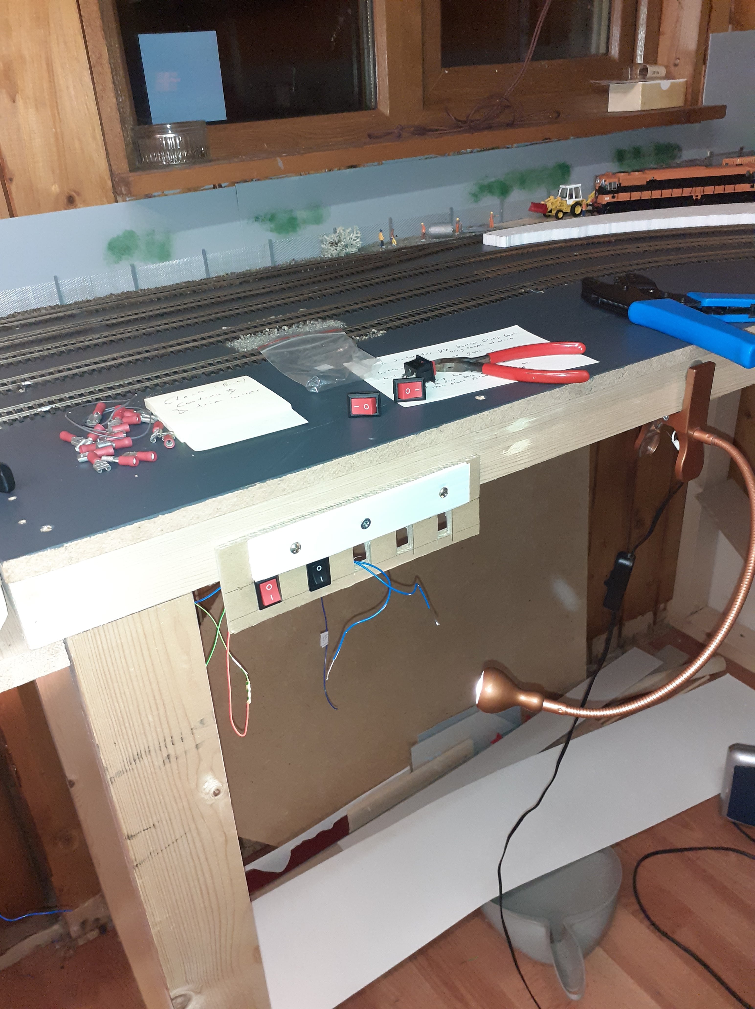
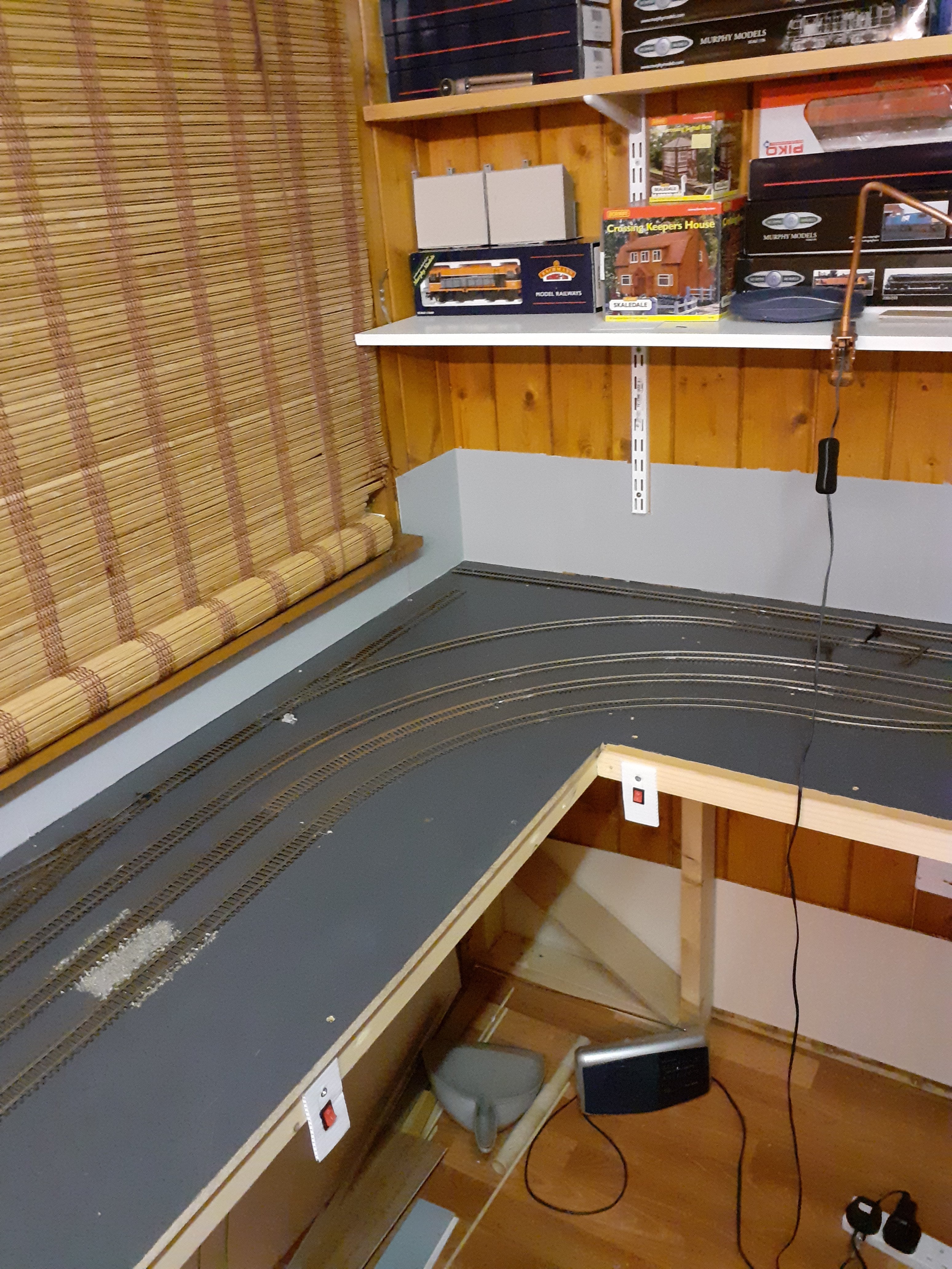
Was doing some rewiring in the lifting flap area and decided to make a virtue of necessity, so i've installed button switches so i can isolate the track on the flap. This area was always going to be semi-scenic and to act as a kind-of fiddle yard, so this w ill alllow me to hold locos in this area while doing other loco movements in the station area.
-
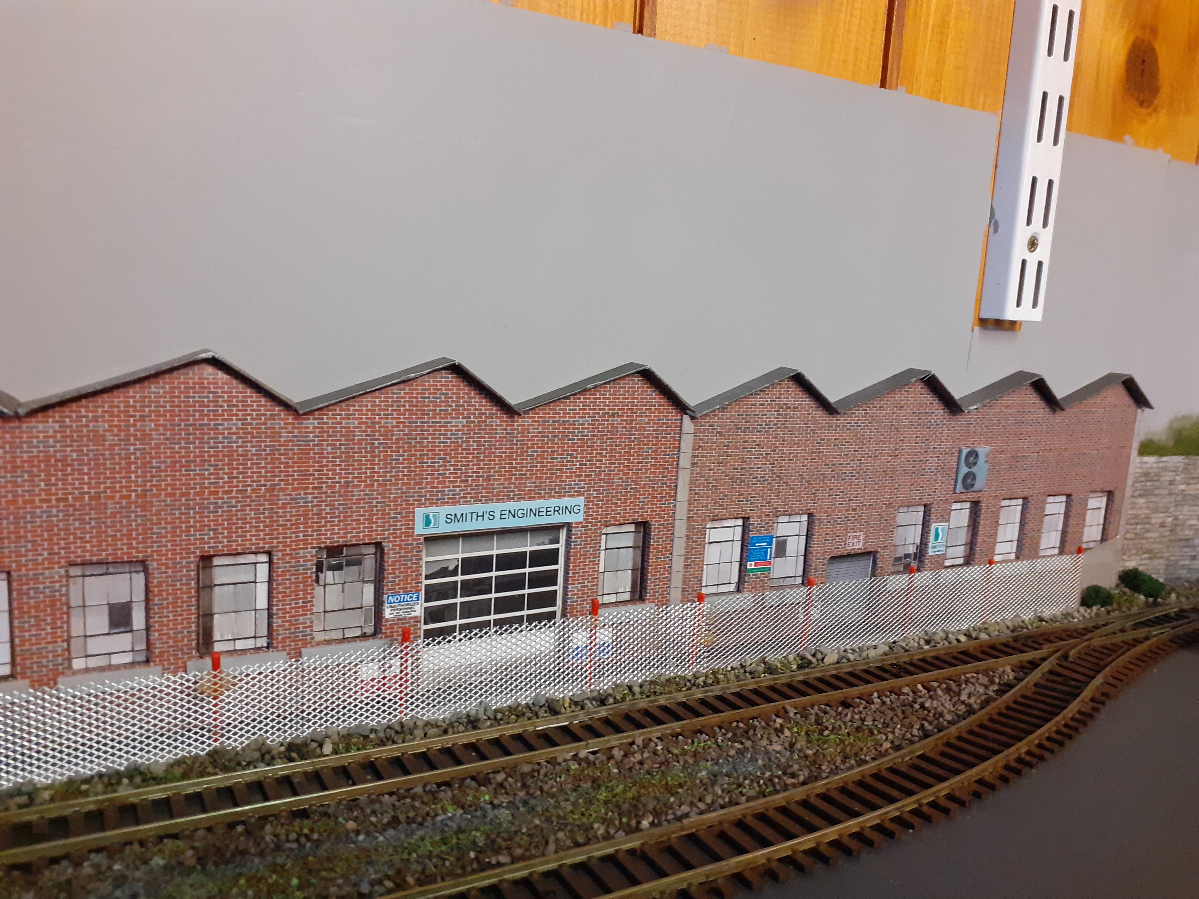
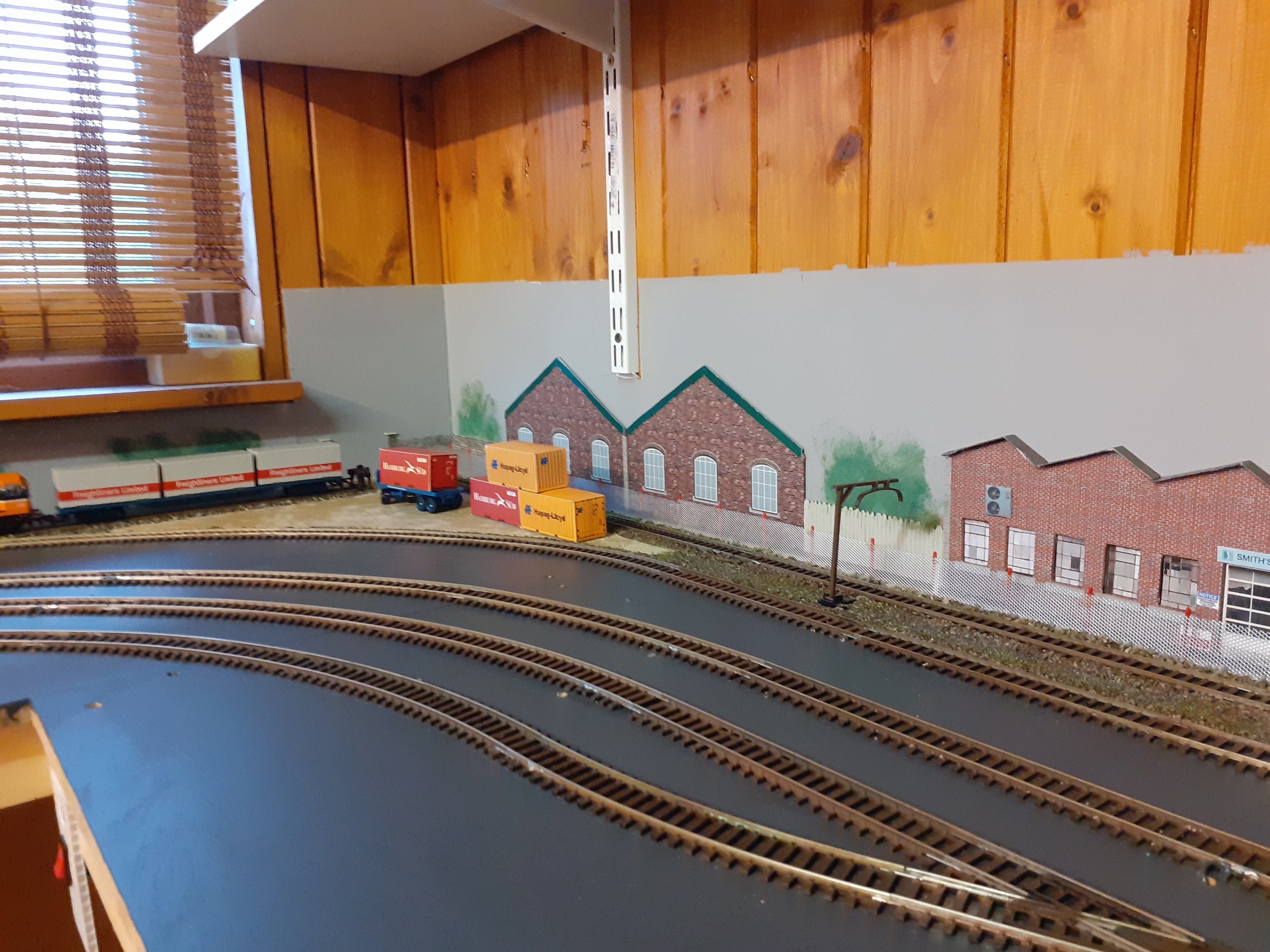
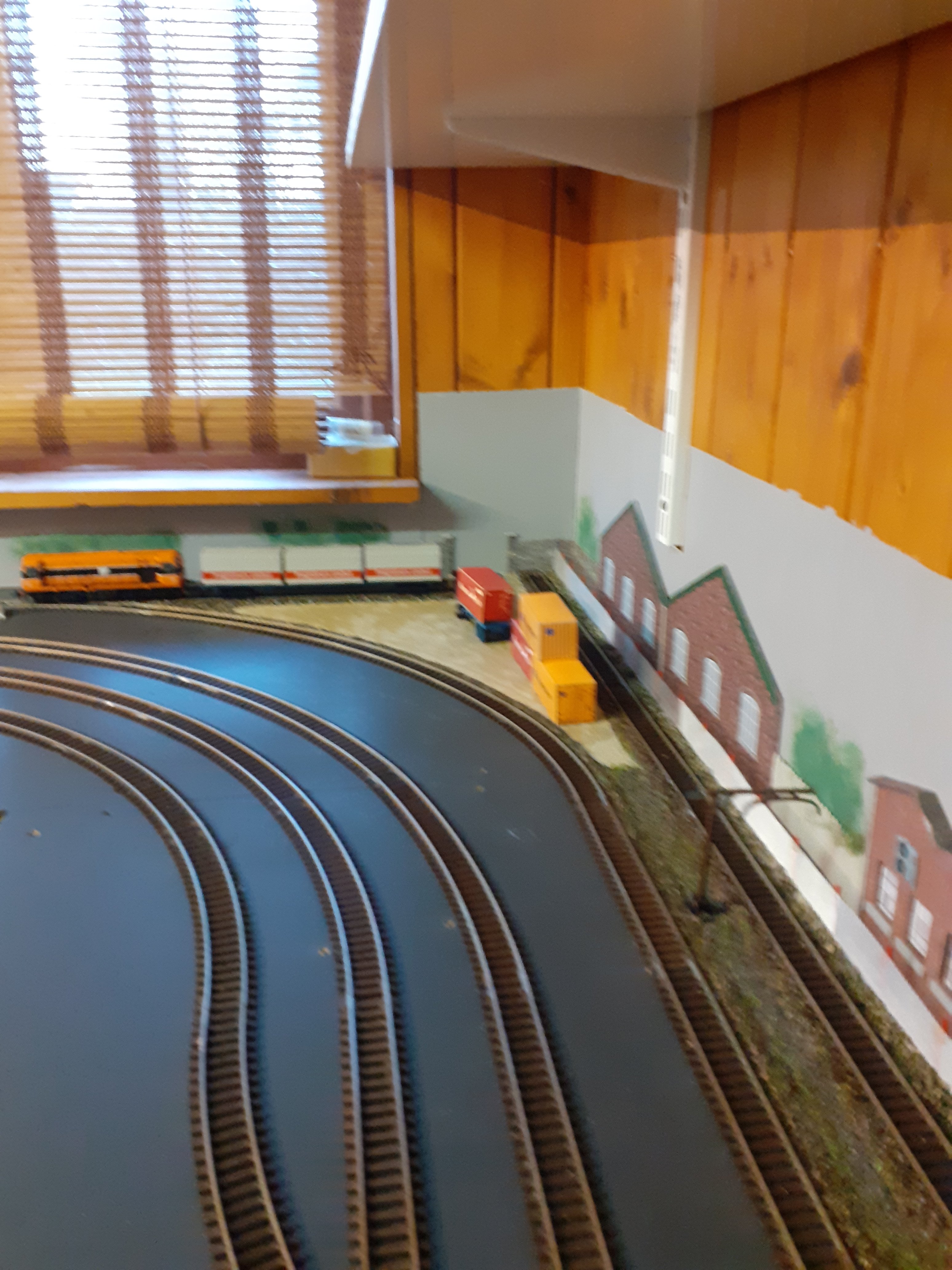
Being doing some work on the back corner before photos and after
-
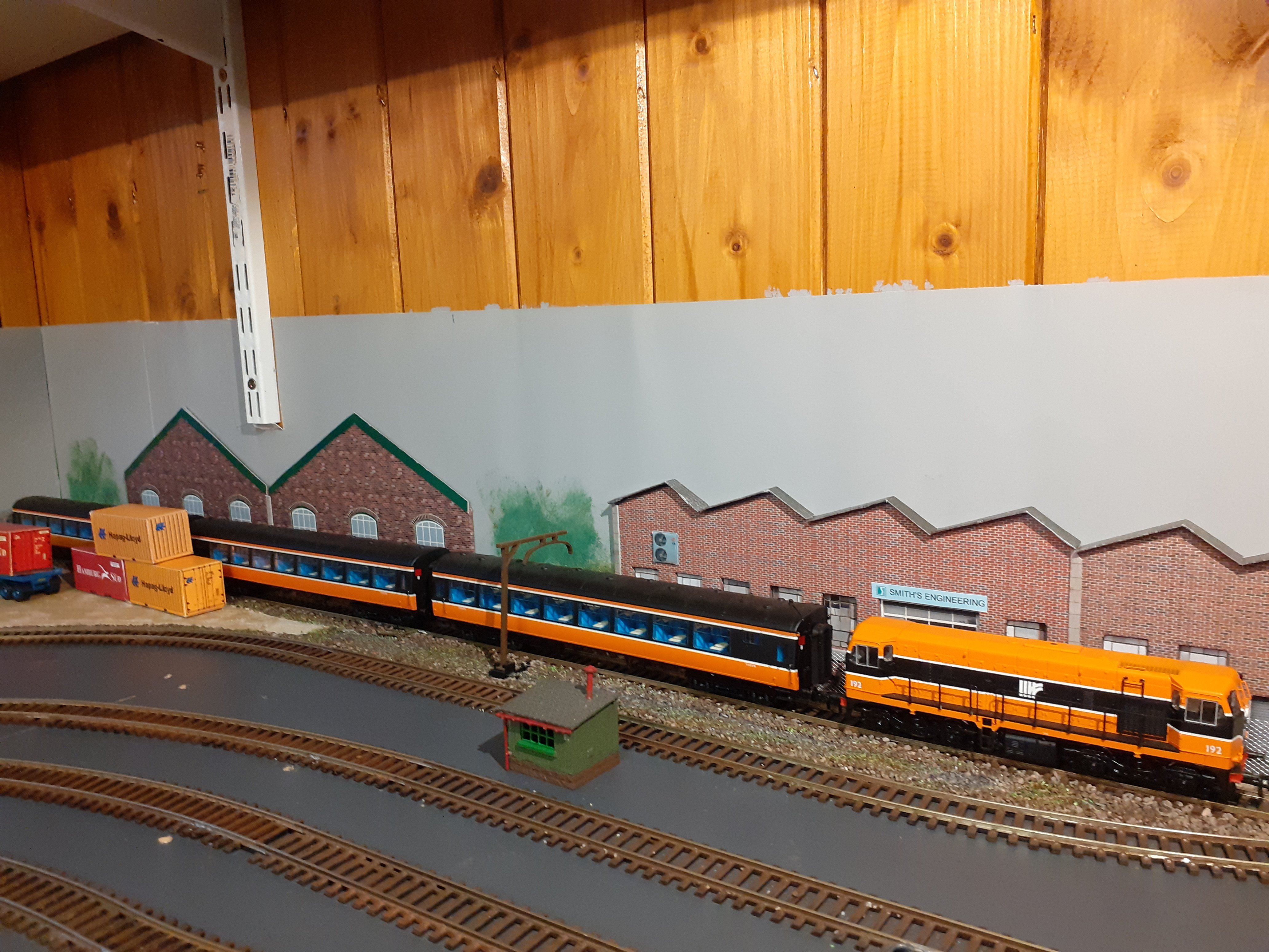
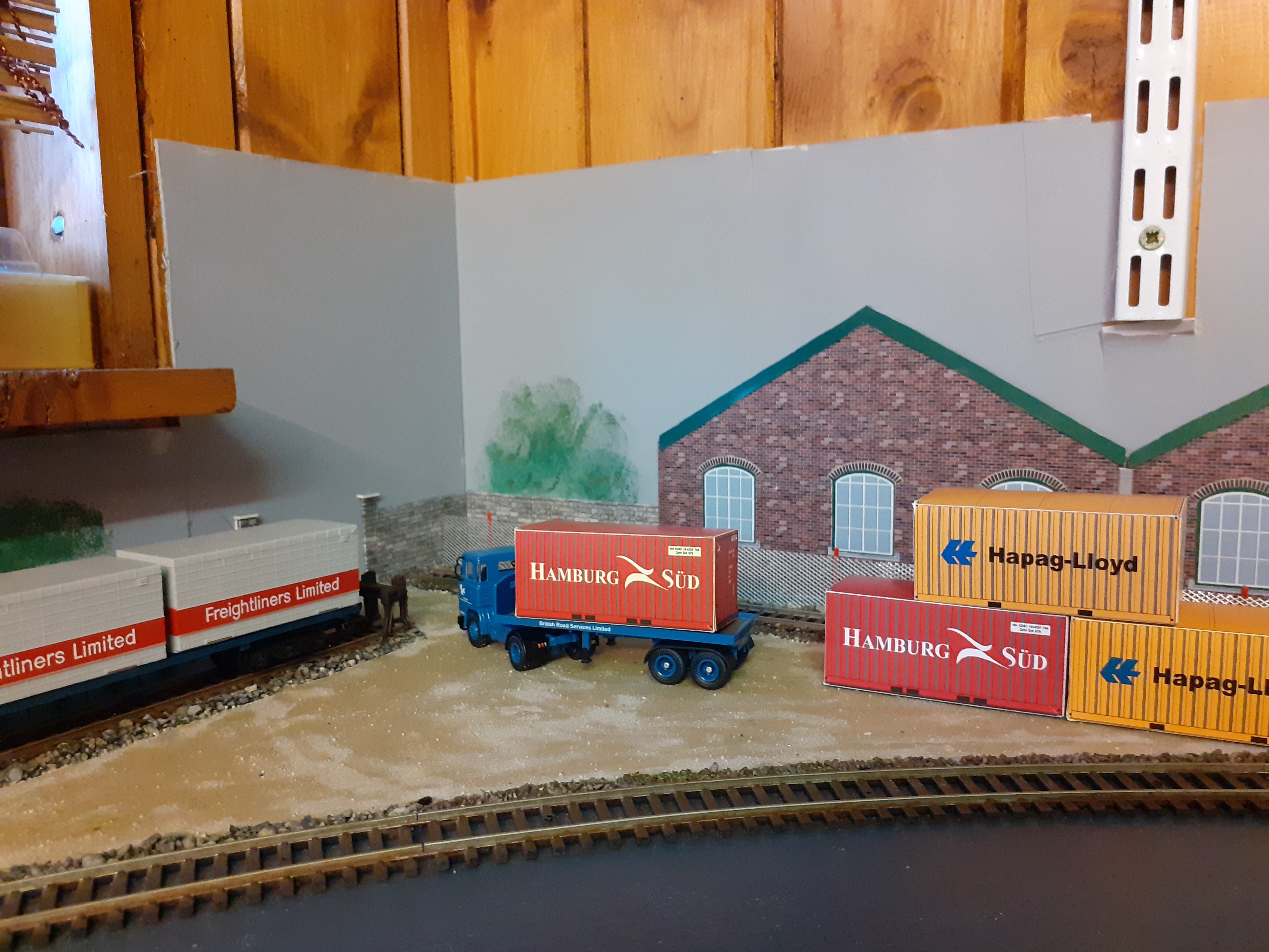
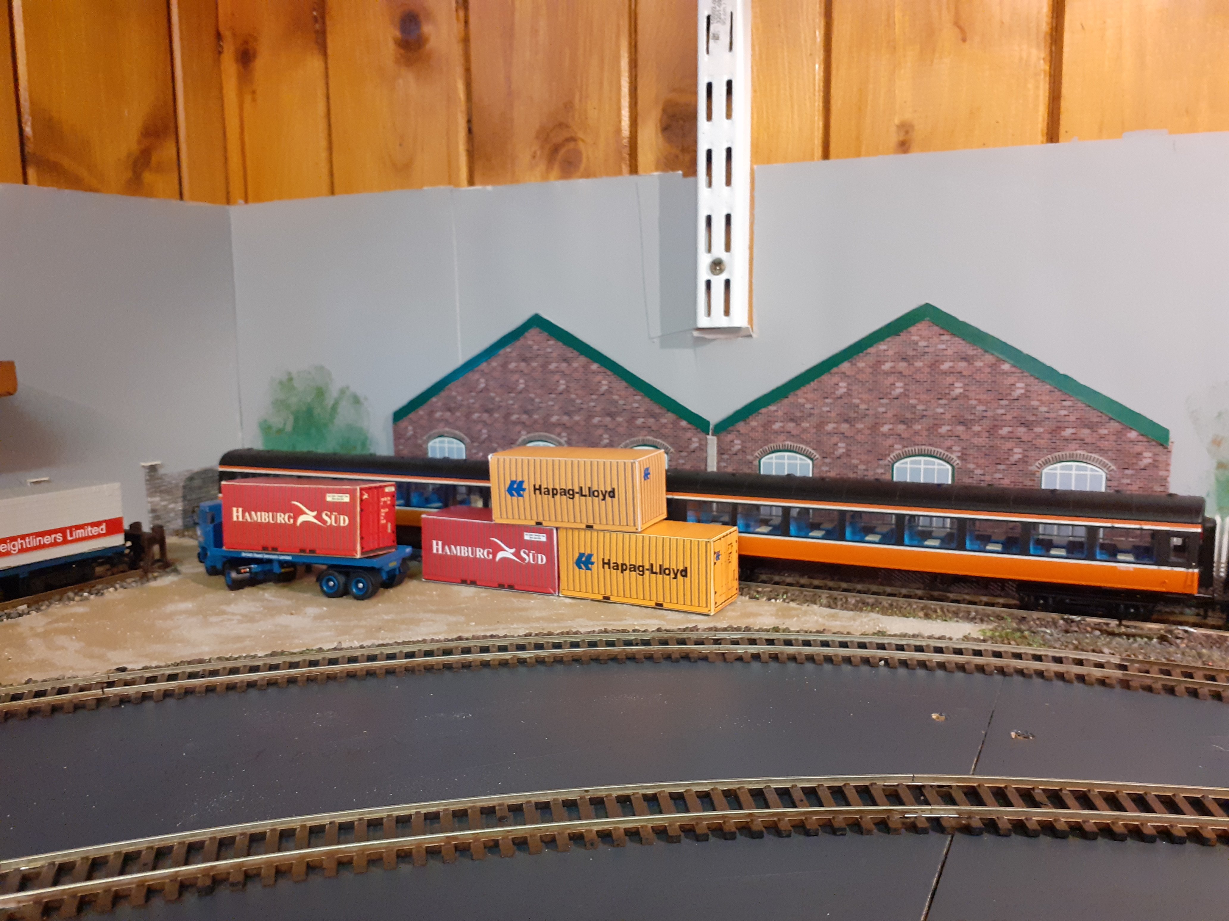
20ft containers. road vehicles and rail bogie
Paddy Mac Namara posted a question in Questions & Answers
Hi want to model a scene with truck containers, i can download card kits of the containers, but i want to get a truck to put them on and also a rail bogie that would be suitable. I only have space to accomodate the smaller 20 ft containers. any ideas where i could source truck and bogies thanks paddy mac -
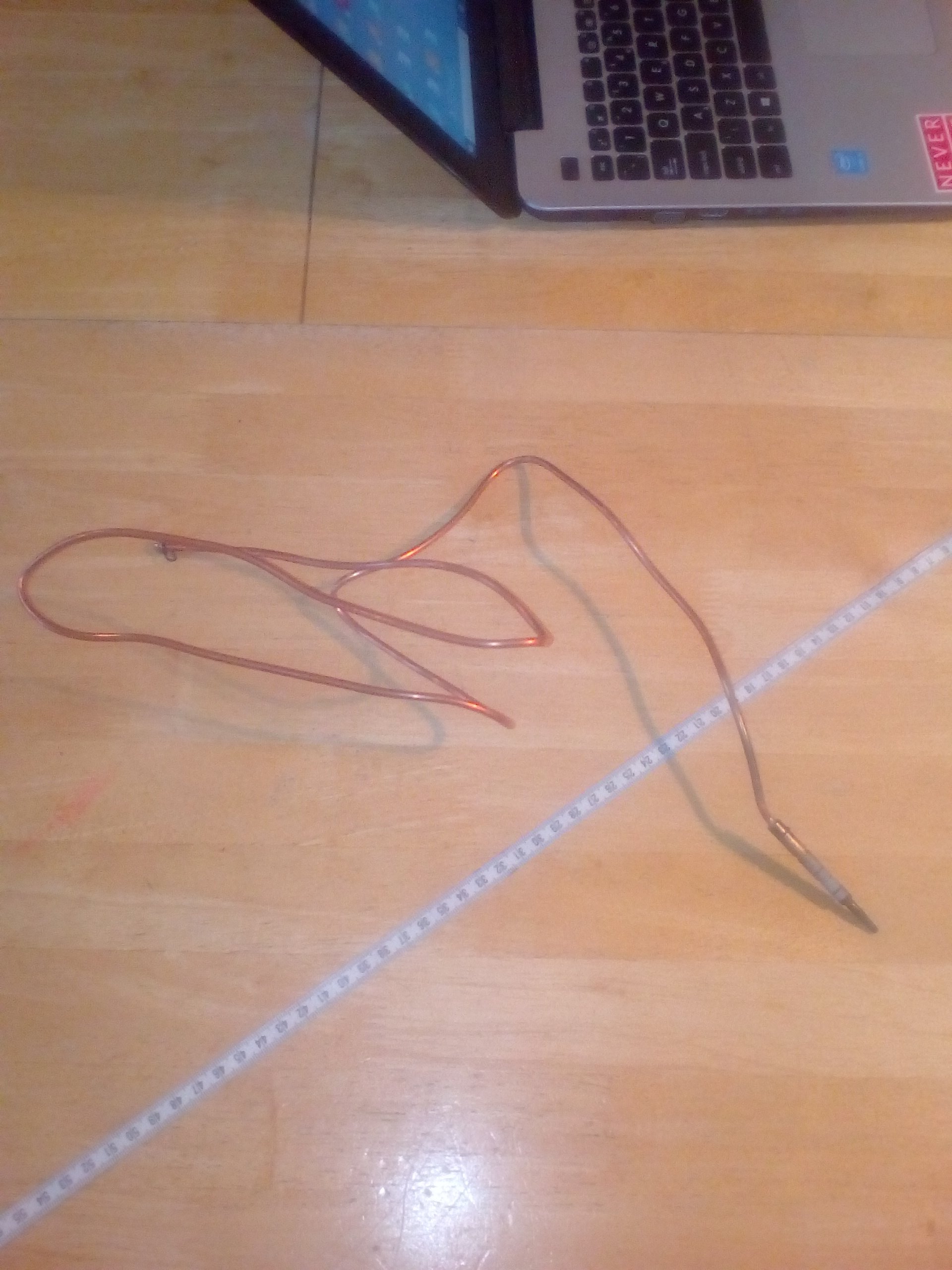
Hi there, had some repairs done to gas oven and this tubing was replaced, thought it might of use for some detail on layout maybe piping or something. I work in town so could meet up to pass on. Its about 3mm diameter paddy mac
-
My first loco build - MGWR ‘Titania’ class 4 tank
Paddy Mac Namara replied to Galteemore's topic in Workbench
a stunning bit of work, "we're not worthy" -
more detail on circuits etc just posted on electronics forum
-
Diamond Crossing Protector
Paddy Mac Namara replied to Paddy Mac Namara's question in DCC, Electrics and Electronics
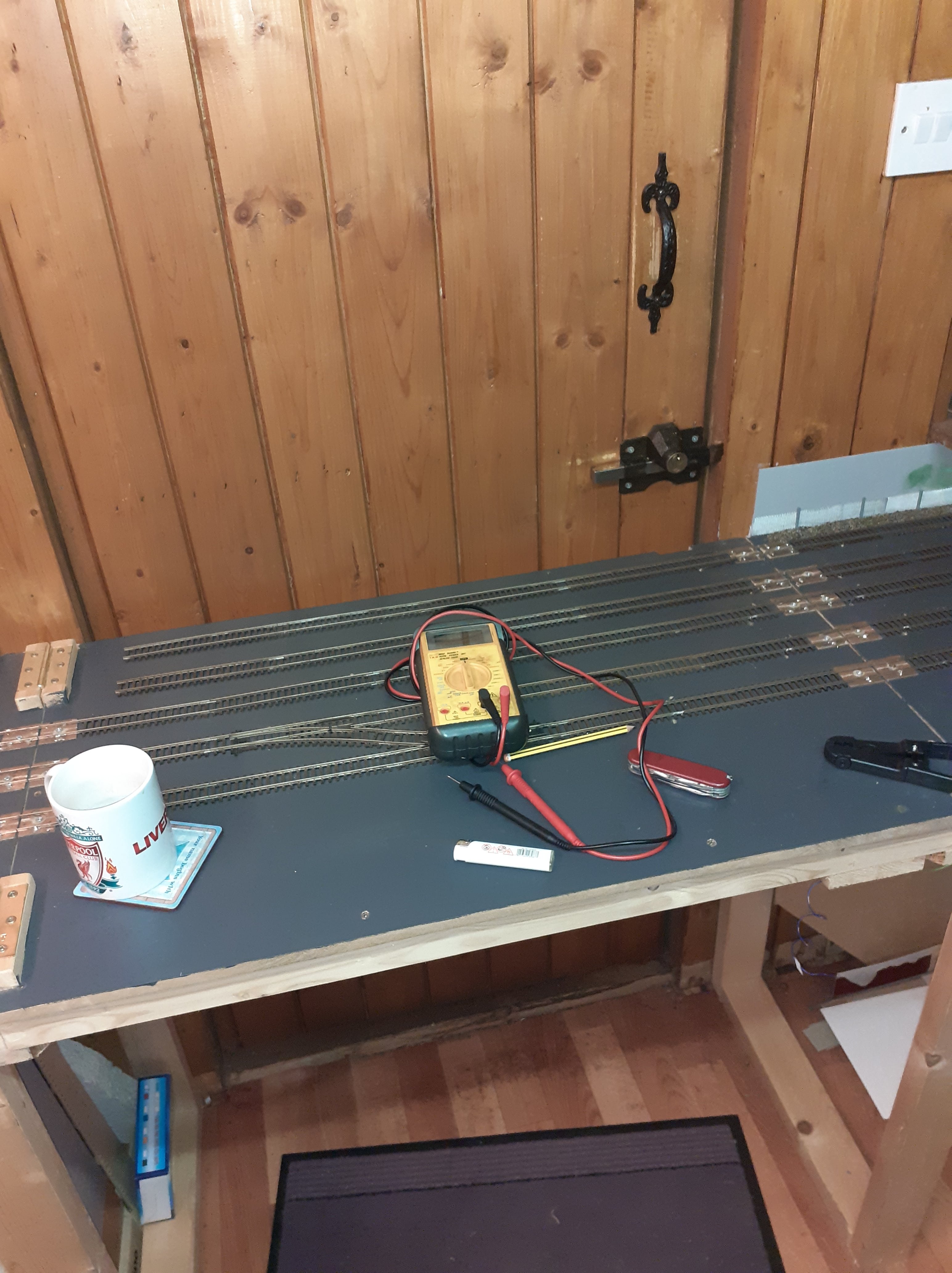
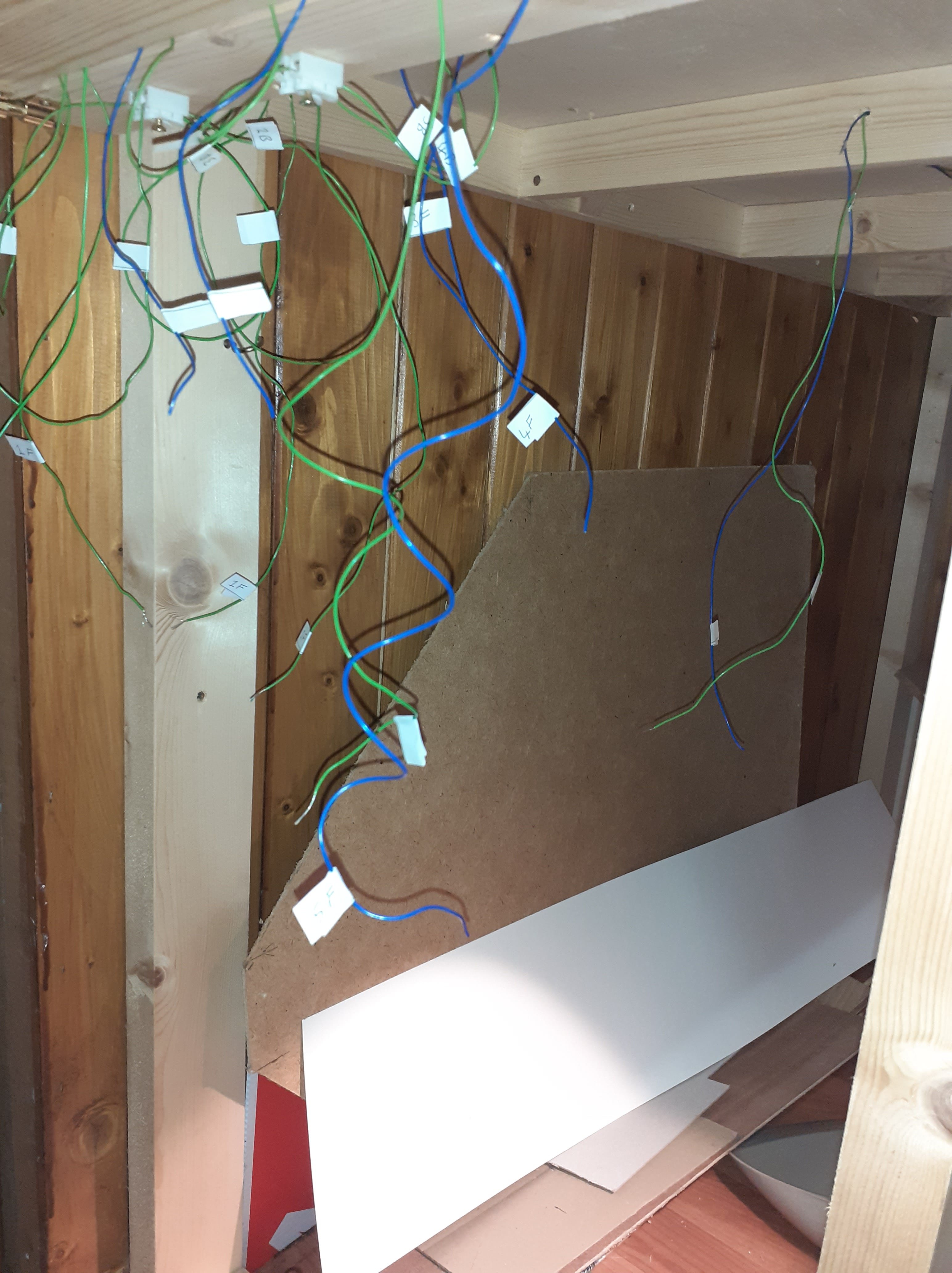
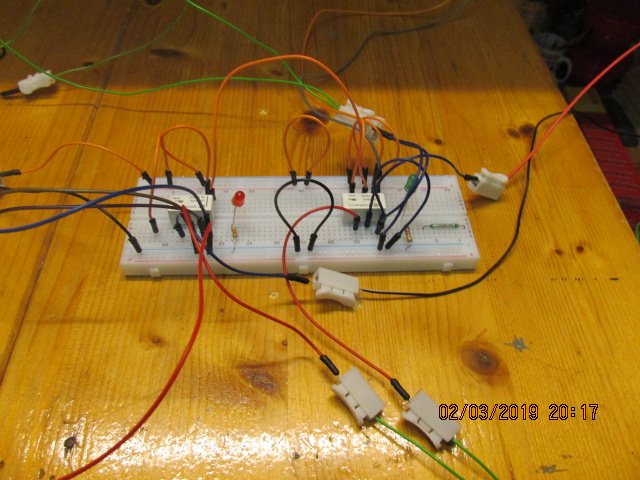
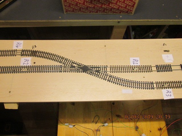
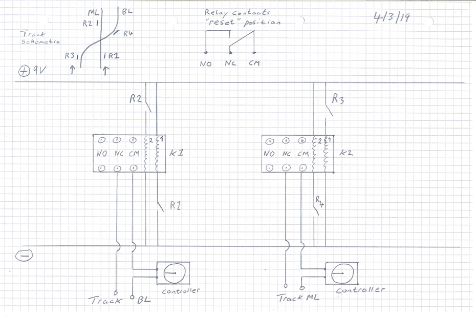
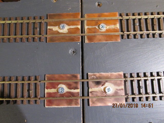
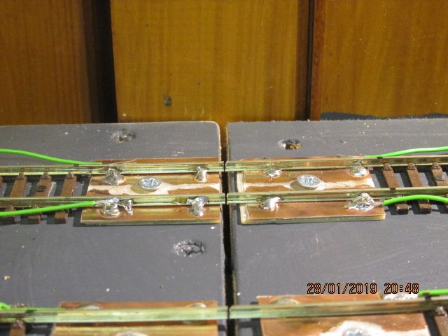
Just a bit of detail on the video posted on “Celbridge” thread. Here is a photo of the track showing the position of the reed switches and a photo of the circuit board. The reed switches are triggered by a magnet underneath the loco. The circuit diagram is shown below, at top of diagram, a schematic of the track with sensors and a diagram of how the pin contacts on the relays work Relay K1 has power to the track connected thru contacts NC (normally closed) and CM (common). The default for the relay is called the “reset” condition. Thus current flows thru NC-CM. So the Branchline (BL) has power “on”. If loco on ML triggers reed switch R1 current flows thru coil 1 of relay K1 and “sets” the relay, this will then switch the contacts from NC-CM to NO-CM so BL is now power “off”. (NO is the normally open contact on the relay). When the loco on ML triggers R2 current flows thru coil 2 of relay K1 and “resets” it back to default, so BL has power “on” Relay K2 operates in the same way and switches power on/off to Mainline (ML). The circuit operates on a first come first served basis, whichever loco reaches the junction first switches off power to the other loco. At the moment the circuit can only work in one direction, I think I can get it to work “both ways”, but I’m having some difficulty at the moment When and if, I ever get around to actually wiring this up on the layout, I will be switching power on/off on isolated sections, so I won’t have locos suddenly stopping dead on the tracks far away from the diamond junction. This project is still evolving and I’m in no major hurry as I have control of the diamond crossing with simple on off buttons. I have two tracks going across the junction, so double the wiring. I have done some coding with Arduino microcontroller and reed switches with some success, but it’s debatable if using software will simplify things as I still need relays to switch on/off current. For those of you unfamiliar with Arduino, it is, I suppose a hobby version of a PLC (used in more industrial applications), very cheap about €30 , very popular for student projects and hobbyists
-
I got the card at work, Bolton st college, we have printing department. So its not commercially available. Try Evans art supplies in town for mounting board or something similar.
-
have a look at the last post on this thread it might help to explain a bit, i will be posting more detail on same forum later
-
I’ve done a bit more work on my diamond crossing protector again using reed switches but I am using two latching relays this time, it operates on a first come first served basis, you can see what I’ve done in the video below. I’ll put more detail with circuit diagrams etc on the electrics and electronics forum for those who may be interested.
-
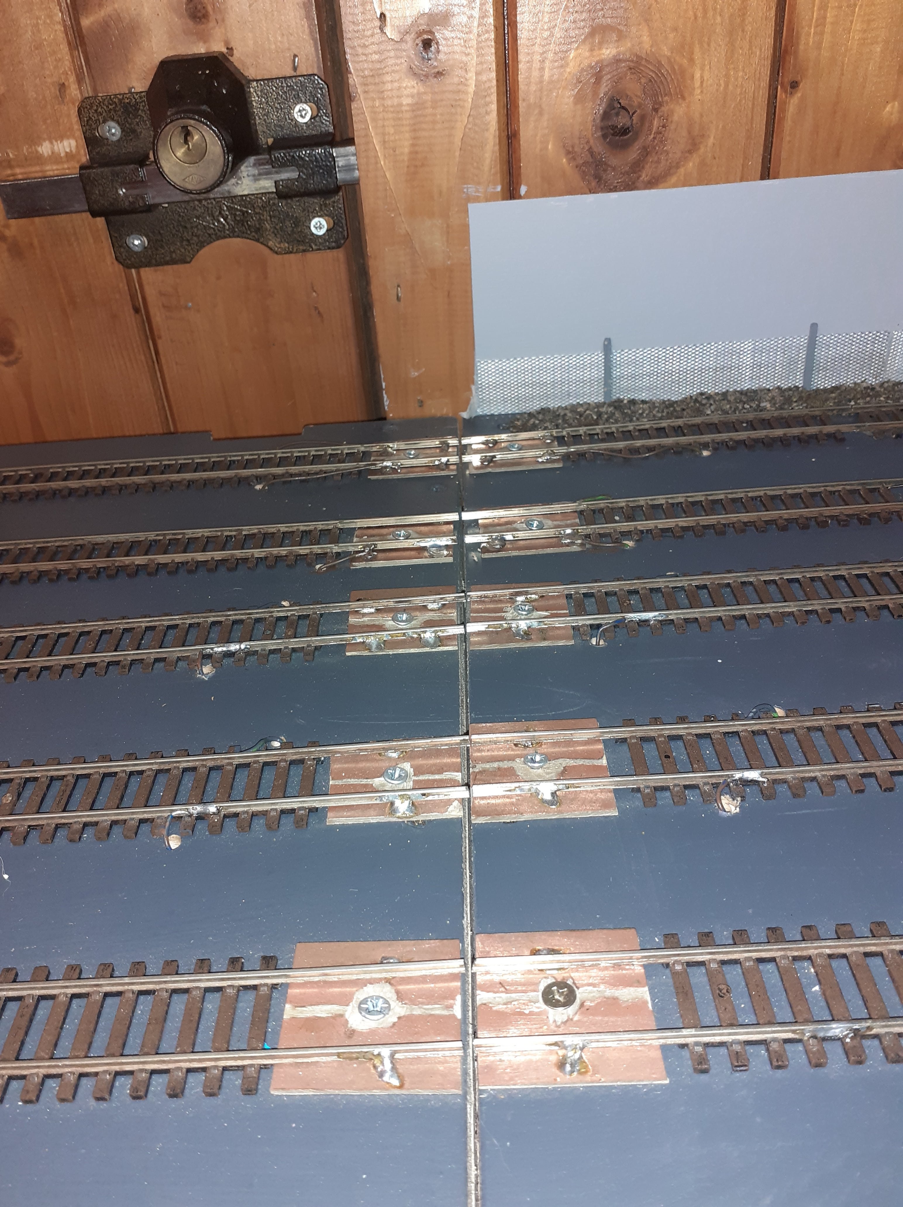
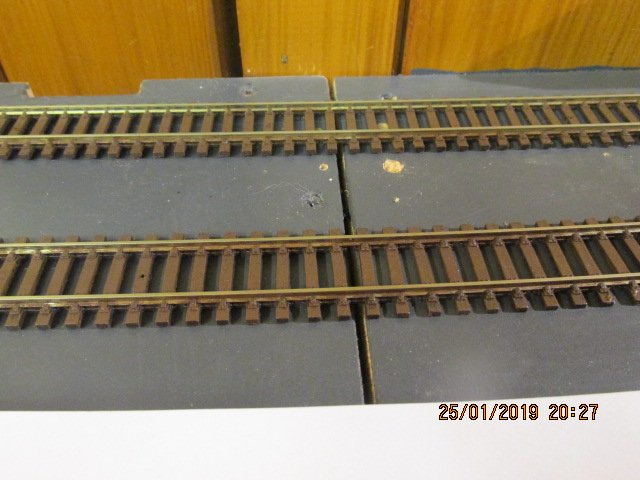
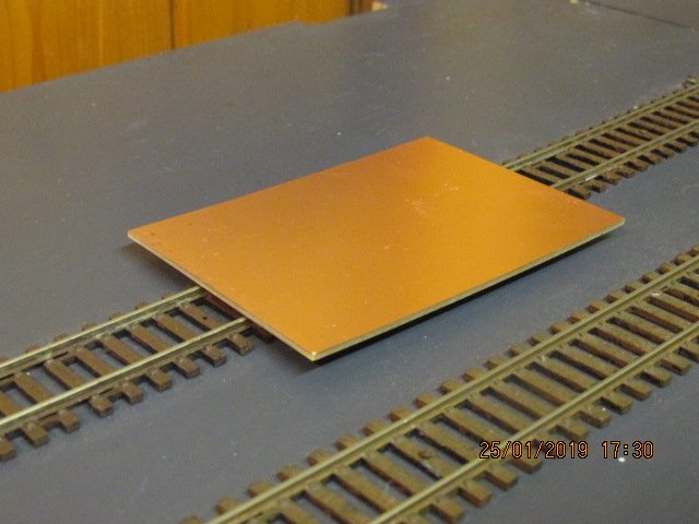
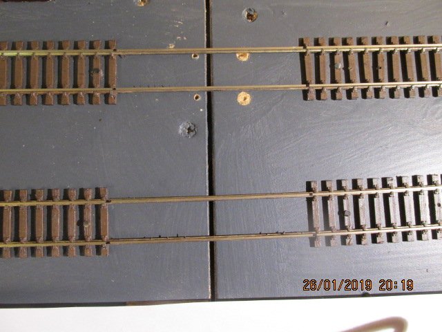
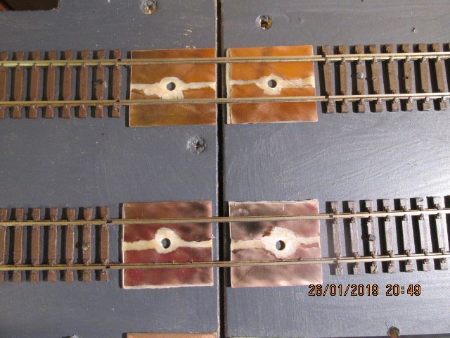
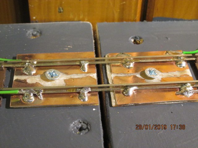
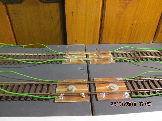
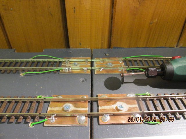
I’m sure many of you have done this before, but for those who haven’t I hope its of interest Paddy Many continuous run layouts have a lifting flap to allow access to a central operating well, so this means cutting the track. I was adding some additional sidings to my layout and figured I would log my progress. Line up your track across the gap, best if gap is in the middle of sectional track and not too near joins. Do some test runs to be sure this is what you want. Cut away sleepers either side of the gap to allow a piece of copper clad circuit board fit under it. I used 70x100x1.5mm single sided, which fits snugly under Hornby track. Cut circuit board to size as required and grind away copper in the middle (or you’ll have a short circuit). Sand the copper side, it makes it easier to solder to. Screw the circuit board down on the baseboard, I use one screw it allows for a little rotation, if needed for adjustment. If baseboard is MDF screwing into it will produce a little lump where the screw pulls up the material as it goes down, so you will need to unscrew and sand this off. Now if everything is in place correctly, (you need to get this right first time so double check) pin down the track either side of the join, firmly but not too much, you want the track sitting securely on the baseboard, but not pressing into it, otherwise it will want to spring back up and exert an unwelcome tensile force on your solder joints. Solder the track to the to the copper clad board. I like a good big blob, solder is quite strong and a larger blob reduces the stress exerted by any external forces. I’ve soldered wires to the board also, these will go under the board and be connected using easy release connectors which will ensure electrical continuity across the track. Now you can cut the track with a Dremel and metal cutting blade. You're good to go!
- 1 reply
-
- 1
-

-
ciaran thats a great use of space for a continuous run layout, trying to figure out where the track goes after the tunnel, do you have a track plan?
-
hi there, love the layout, i like to see my trains run around, and the elevation, always wanted to try that....more details please. also do you have a name...i don't quite get the use of sobriquets on the forum...or god forbid avatars...what are we.... 12? cheers patrick michael mary (yes!) mac namara
-
thanks
-
just checking guys, is the bray wheelers swapmeet/sale still on next sunday? cheers paddy mac
-
OO Irish freight wagons, vans etc
Paddy Mac Namara replied to Paddy Mac Namara's topic in Irish Models
Hi all, and many thanks for all the help. I would like to acknowledge the generosity of spirit shown by members of this community, for your time in responding and sharing of your knowledge. I remember only a couple of years ago, wrenneire (dave?) you gave me some track for free, and very useful it was too. I'm at this about 12 years now and on my 4th layout, but still so many skills to learn and master. cheers guys (no gals on the forum...i'm not sure) -
OO Irish freight wagons, vans etc
Paddy Mac Namara replied to Paddy Mac Namara's topic in Irish Models
sorted, looked at some photos online, dirty grey with lots of weathering seems to the answer -
OO Irish freight wagons, vans etc
Paddy Mac Namara replied to Paddy Mac Namara's topic in Irish Models
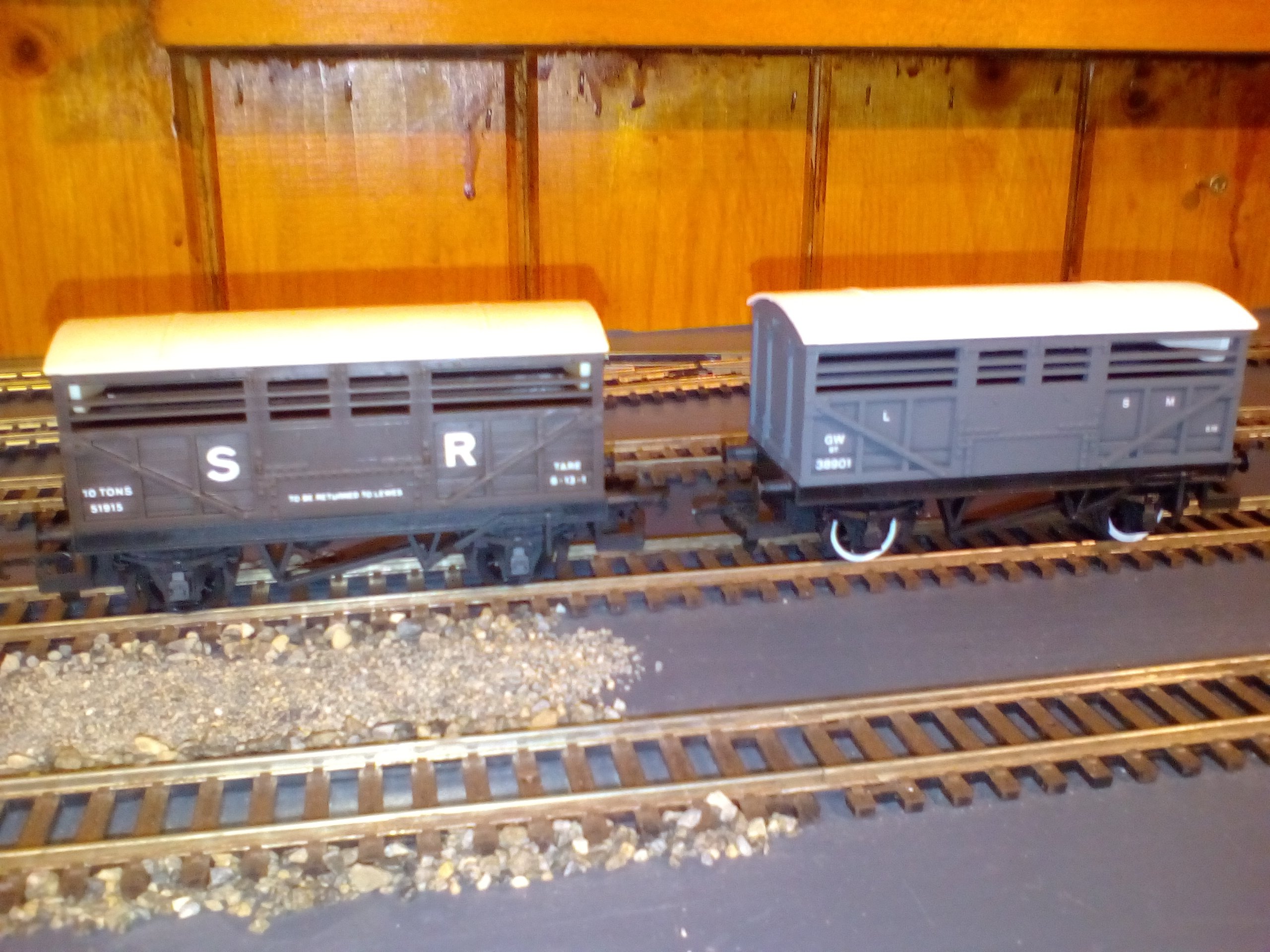
i have several of these cattle wagons, any suggestions for colour of body and roof?
-
OO Irish freight wagons, vans etc
Paddy Mac Namara replied to Paddy Mac Namara's topic in Irish Models
some great suggestions there lads and fab work on the respray jobs. wrennery, yes i would be interested where is the bray wheelers gig on cheers paddy mac -
OO Irish freight wagons, vans etc
Paddy Mac Namara replied to Paddy Mac Namara's topic in Irish Models
thanks for all the replies/advice it'll take me a while to consider, thanks again paddy