Paddy Mac Namara
-
Posts
186 -
Joined
-
Last visited
-
Days Won
1
Content Type
Profiles
Forums
Events
Gallery
Blogs
Community Map
Everything posted by Paddy Mac Namara
-
Thanks for comments guys. I think my favourite is 2nd layout, goods yard terminus with loop under the "mountain". Kinda sorry now i dismantled it.
-
welcome Thomas,looking good so far. cheers paddy mac p.s. you might not realise it but we love a new layout on the forum.
-
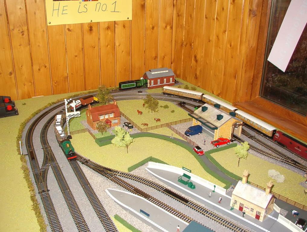
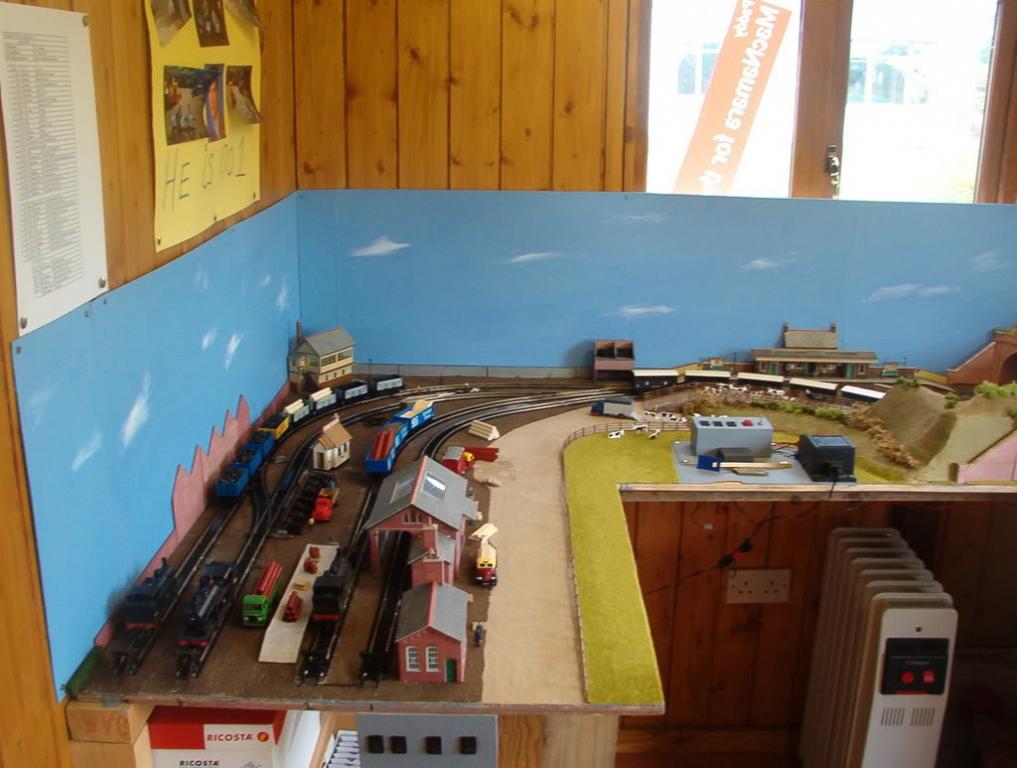
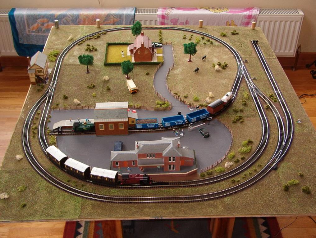
and last one kids layout

-
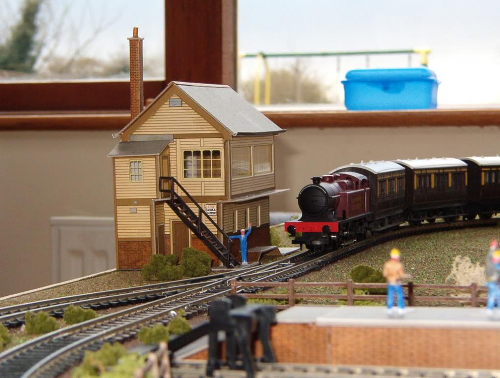
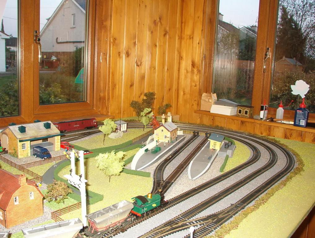
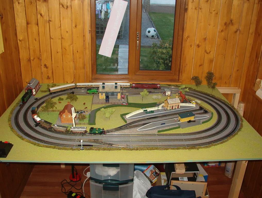
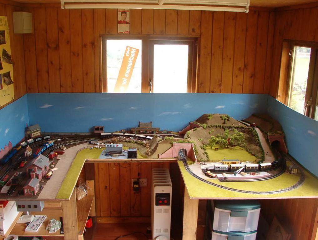
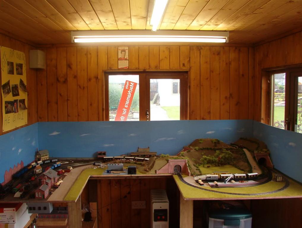
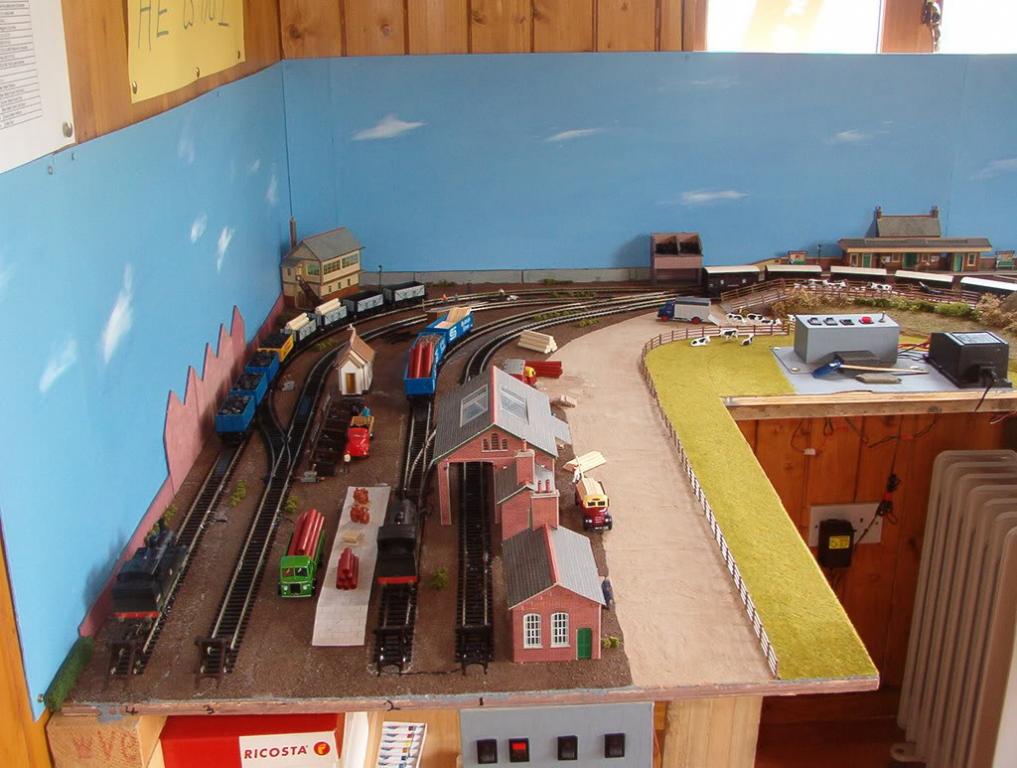
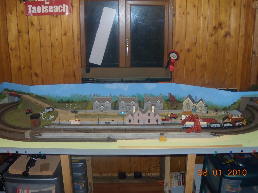
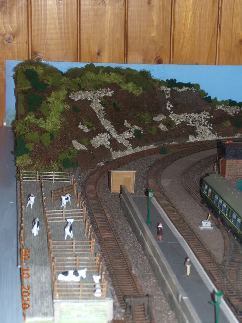
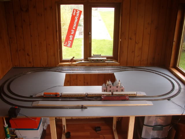
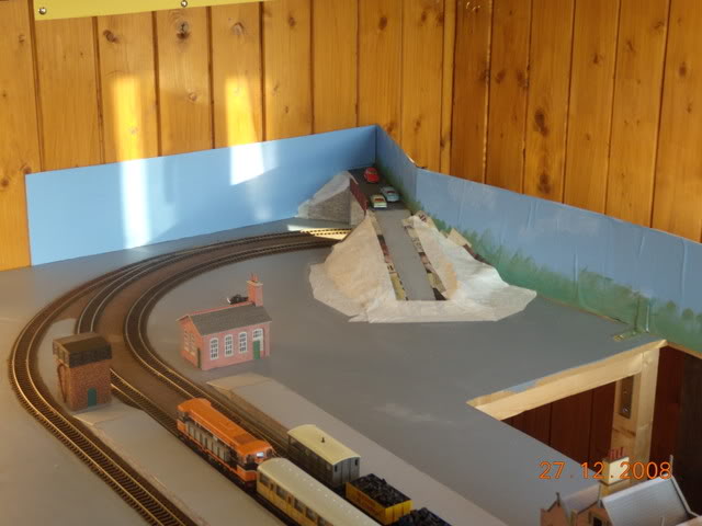
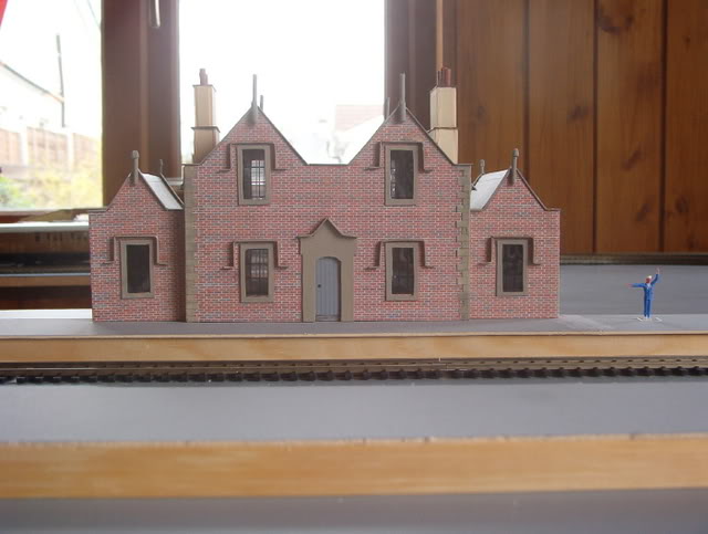
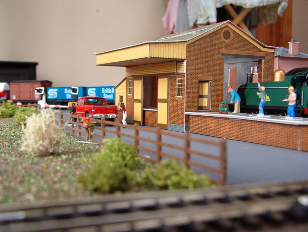
I hope this might of interest to new and old modellers alike to show how the “addiction”…oops sorry… hobby progresses. Below are photos of my old layouts.(I remembered I had them on photobucket) some of them featured on the old forum. I suppose as for most of us my first layout started with a Hornby starter set when I was around twelve (cue barrys tea ad). By the time I was 16, it had progressed to a double track layout (I think) on an 8 x 4 chipboard in my bedroom, I had some station buildings and a couple of locos. I remember I used to buy track directly from Hornby with postal orders…..aah remember the days before ebay. Anyway it wasn’t girls or cars that distracted me from the hobby but we moved house, and there wasn’t enough room for it, I managed to sell the layout to a rather unpleasant man. So fast forward to 1999 and my wife (oh how naive of her) bought me a flying scotsmans set. Set it up and played with it a bit…but had no permanent space for it (the ankle biters had arrived). Until 2004 when I got my shed/office in the garden. So 1st layout was around 2006, 2nd 2007 around this time the kids were getting curious so I built them (me) a layout to keep them away from mine. 3rd layout around started around 2008 and completed 2010. Now in 2010 I started playing golf, which in itself does not interfere with modelling time as I usually prefer to model during the winter evenings, but it does distract one and can be and is very time consuming (wasting?)….so in 2014 I was able to start the process of devoting the entire office space to a layout… just took a bit of time dismantling the old layout and sorting things out before I could start on the new one and that’s where I am now…. 1st layout 2nd layout 3rd layout
-
hi rich, love the layout, where did you get the class C C229 loco. BTW i think the double curve in the corner looks fine. cheers paddy mac..
-
Begining of the end of the Old Layout.
Paddy Mac Namara replied to Kirley's topic in Irish Model Layouts
Its like losing an old friend....but also exciting if you are starting a new layout...i'm on my 5th layout -
Diamond Crossing Protector
Paddy Mac Namara replied to Paddy Mac Namara's question in DCC, Electrics and Electronics
Thanks for comments and suggestions, still very much WIP, and I got a lot of help from friends at work. -
hey there "chevron", if i remember right, u got a load of railway modeller mags from me... hows the layout going? cheers paddy mac
-
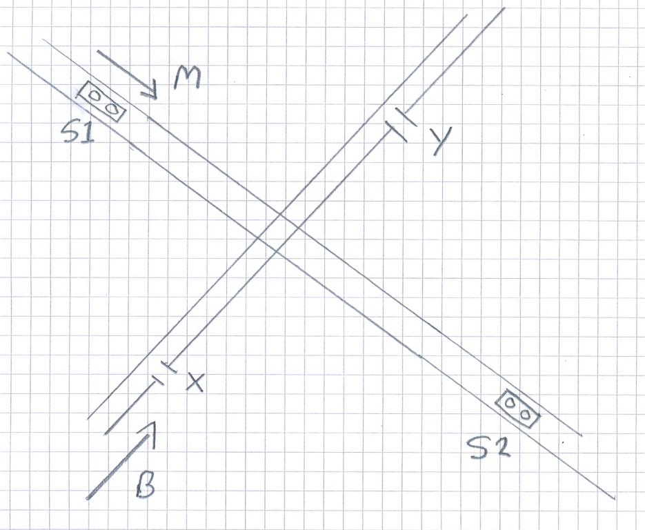
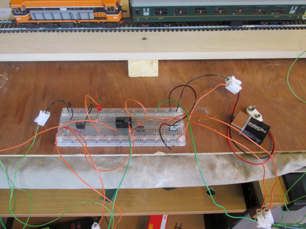
This item didn't appear to rouse much interest over on the layout forum (Celbridge), but may be of interest to those who prowl this forum. Anyway please let me know what you think. Here is a more detailed description of what’s involved. In the diagram below of crossing, M is mainline B is branch-line. So what we want to do is allow the mainline have priority over branch-line and of course avoid collisions. The branch-line is isolated between points x and y. There are sensors S1 and S2 on mainline, when S1 or S2 detects a train power is cut on branch-line. The next diagram shows how the isolated section can be controlled with on/off switch and then replacing the on/off switch with a relay. Also a diagram with relay pin-outs shown. What the electronic circuit does is allow the sensor to switch on/off the coil on the relay which in turn turns on/off power to the track Below is the detailed circuit diagram. What does it do? With S1 or S2 = 0 (no train detected) Transistor T1 and T2 are on because current goes to base (b) of transistor and turns “on” the collector-emitter (c-e) circuit thus the relay coil gets 9v. The relay is wired to either side of isolated section on branch-line through the common (CM) and normally open (NO), which is an open circuit, but because the coil on the relay is active the relay switches and the CM-NO circuit closes so we have power to the isolated section. So this is the normal operating state of the circuit, relay coil active and thus power to isolated section. Now when a train passes over S1 or S2 (S1, S2 =1) the infrared light from the diode on the left of S1 (the triangle thingy) is reflected back to the right hand side and this activates the transistor circuit in the sensor to “on” so now current is diverted from the base of transistors T1, T2 to ground. This switches off the c-e circuit so no current passes thru the relay coil, which is now in its off state so the CM-NO circuit is now open and no current flows to isolated section. I have a video of a test track for the circuit over on Celbridge thread on layout forum. There are some problems with this in practice, the photo-sensor doesn’t work so well on the black undercarriage of our models…so I had to paint them white. The sensor is only active when it detects something over it, so one needs a long train to ensure that one or both sensors is covered as a train is going thru the crossing. Also what happens if branch-line loco is already on the crossing as a mainline loco triggers the sensor.Power is cut to branch-line so it stops in the middle of the crossing….crash…bang…oops !!!!! This is really just the start of trying to design something more comprehensive, it will work fine if the timings of branch and mainline are lagged correctly and you keep an eye on things. I’m not going to install it on the layout just yet I want to think things thru a bit more. Am I going to need more sensors on branch-line, could a latching circuit be better. Would reed switches be better…etc. etc? Do I go the whole hog and use an Arduino microprocessor…..why didn’t I go DCC in the first place….?????....i know, I know.
-
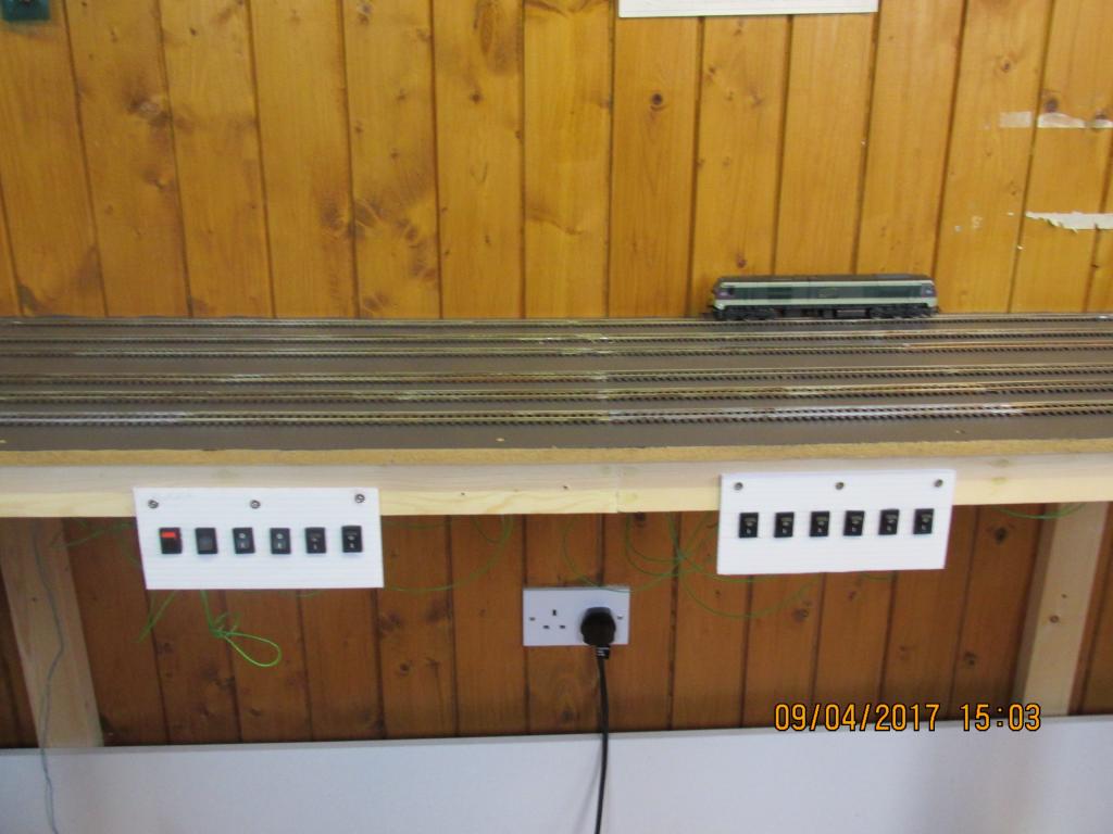
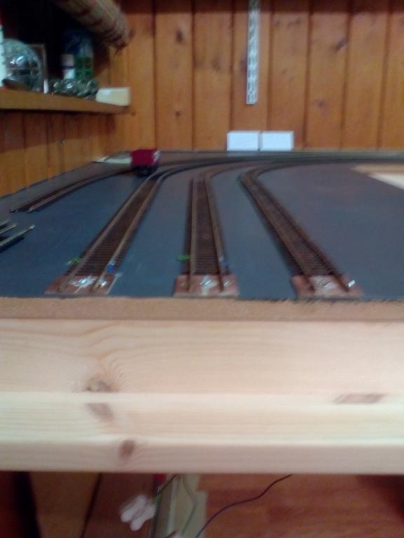
I've been doing a lot of soldering and wiring recently. There are 6 tracks in the station area. Each track has now two isolated sections. This will give me a lot more flexibility operating trains. Need thing to tackle is some scenic work.
-
and some photos
-
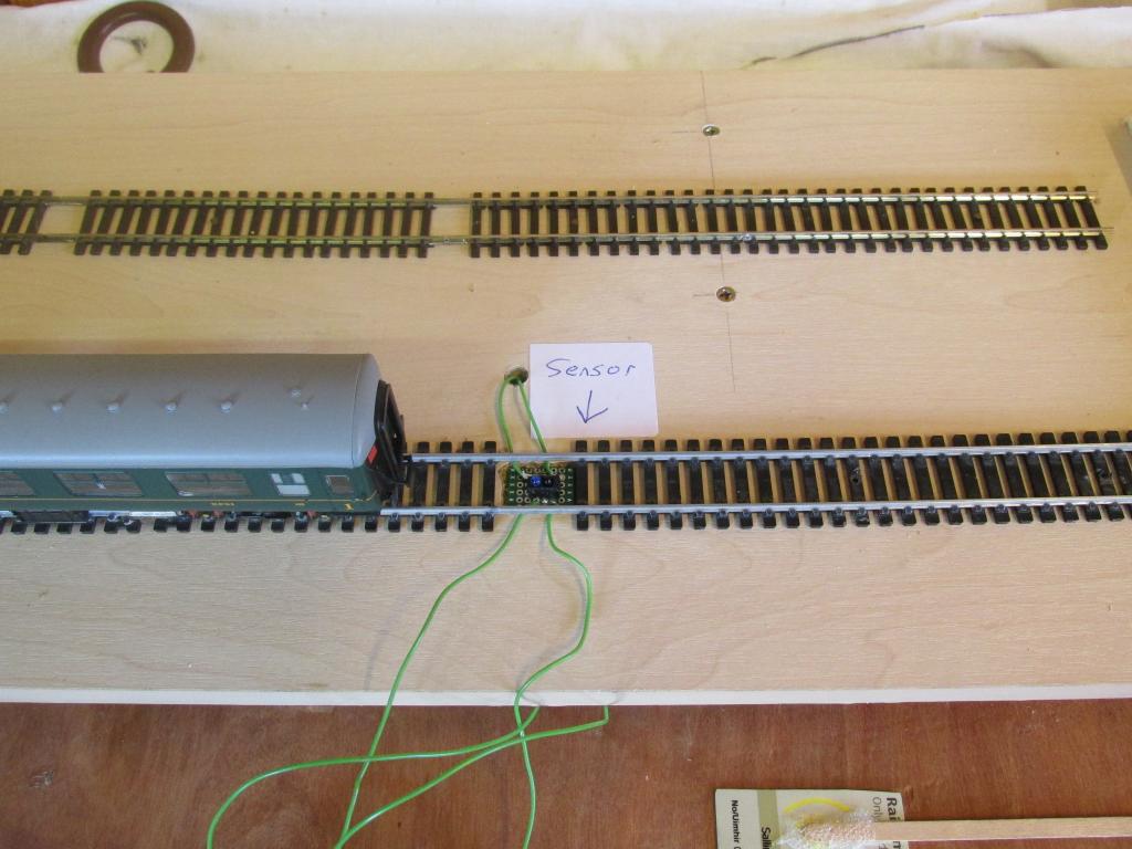
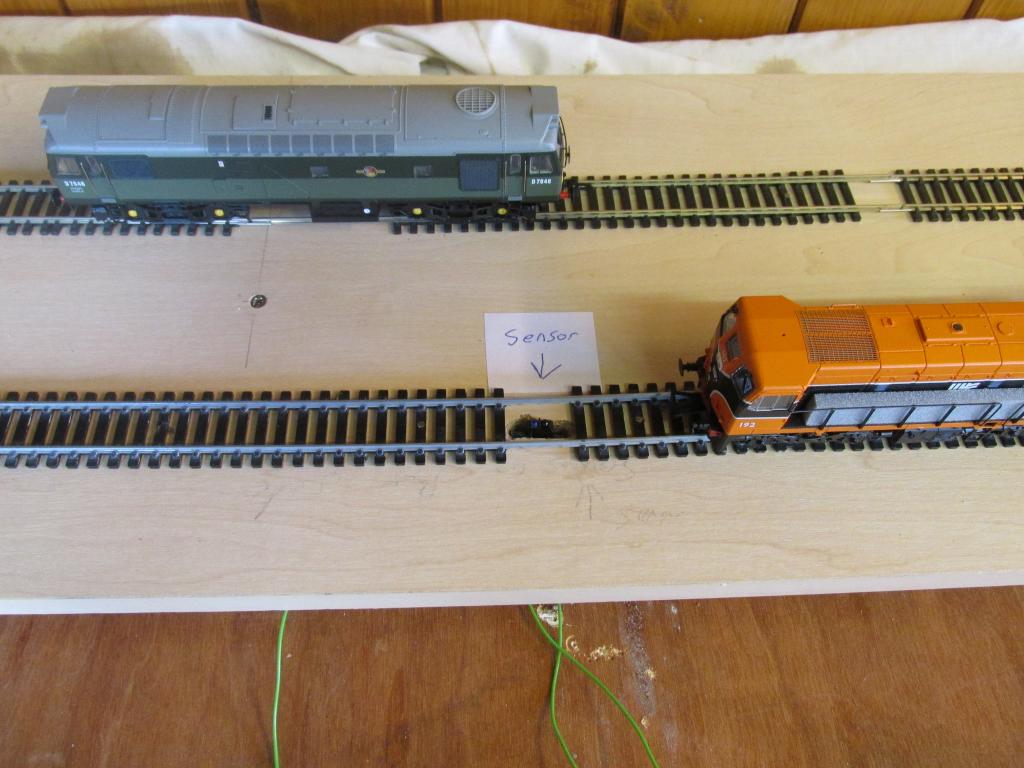
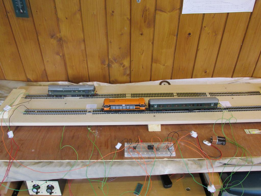
As mentioned above I want to control trains thru the diamond crossing automatically, as opposed to switching on/off isolated sections. I have a control circuit using Infra-Red photo sensors. On the actual layout, see above, sensors on the main-line (yellow) will detect a loco approaching from either side of the junction and shut off power to the other two lines (blue and light blue) I wanted to test it out first on some spare track (thanks Dave). This has proven very useful and was a good trial and (lots of) error, before attempting it on the real thing. The videos and photos hopefully will clarify things. The orange loco is on the mainline and the other loco is on, say, the branch line. There are two sensors on the mainline when the orange loco goes over the sensor power is cut off to the other loco and it stops the branch loco. The orange loco couples with the carriage which goes over the second sensor and power remains off. Anyway it proves the concept works. I’ll post a more detailed description of the circuit and how it works on the electrics and electronics forum. I can’t take any credit for the circuit design. I am a teacher in Bolton st (mechanical engineering) and am lucky to have plenty of technical expertise available. My colleague Graham Gavin designed the circuit, and I had plenty of additional tech support from Martin Byrne.
-
hi peter, good to reply to someone with an actual name, short answer is yes, cos carriages can derail on tight curves. post up a photo/diagram of your track layout to assist. cheers paddy mac
-
Help - need small piece of paving
Paddy Mac Namara replied to GNRi1959's question in Questions & Answers
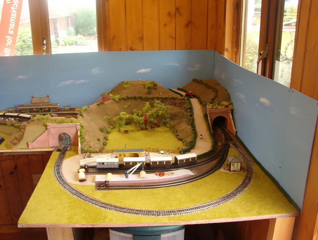
I like tapered platforms...they look neat and tidy. -
Help - need small piece of paving
Paddy Mac Namara replied to GNRi1959's question in Questions & Answers
cheers tony, any photo on forum of the full platform. its 50 mm wide? -
Help - need small piece of paving
Paddy Mac Namara replied to GNRi1959's question in Questions & Answers
Tony, hi there, i like the look of that platform kit, is it OO do you know wills part number? cheers paddy mac -
God bless your eyesight achill ... There were indeed wine bottles in there was trying a spot of home brewing..... Can't see them on the thread tho...?
-
Thanks. It's coming along....
-
Video showing operation of isolated sections as mentioned above.
-
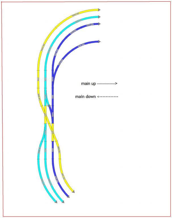
So my next challenge is to sort out the electrics for the two diamond crossings. In the track diagram below, the yellow track is mainline, down, the dark blue is mainline up, and the light blue is commuter line, up or down. So the objective is to have yellow track having right of way all the time. I have whole sections of the other tracks isolated either side of the junction and simply turn off the power to stop trains entering the junction when mainline train is coming. (I have something similar on the other side of layout). So this arrangement is rather cumbersome and you’d literally need eyes in the back of your head when operating three trains. I must see about posting a video of this operation. I’m working on a control circuit with sensors, something like that available from Heathcote, but without the need for an Arduino micropressor. More of that in time. Cheers, paddy mac
-
Wanted: old/scrap oo straight track
Paddy Mac Namara replied to Paddy Mac Namara's topic in For Sale or Wanted
altho i see from your location ur in Dublin 5 ??? not too far from me i work in bolton street -
Wanted: old/scrap oo straight track
Paddy Mac Namara replied to Paddy Mac Namara's topic in For Sale or Wanted
thanks...i'm in sallins near naas -
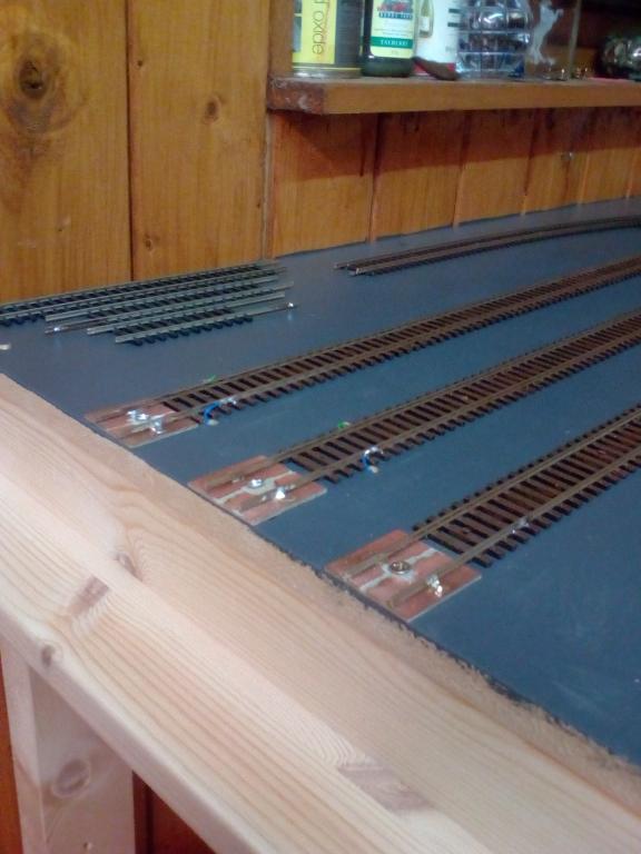
still looking for some track want to make a test track for some electronic i'm doing at the moment. thanks paddy mac
-
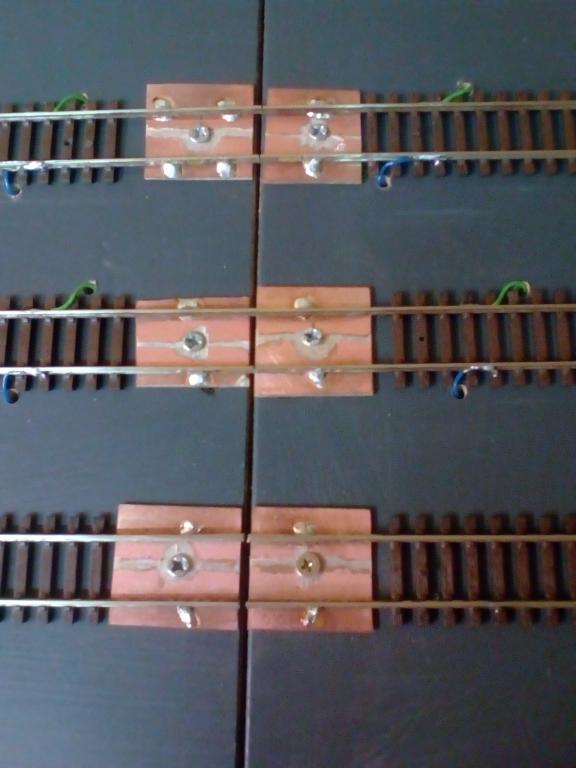
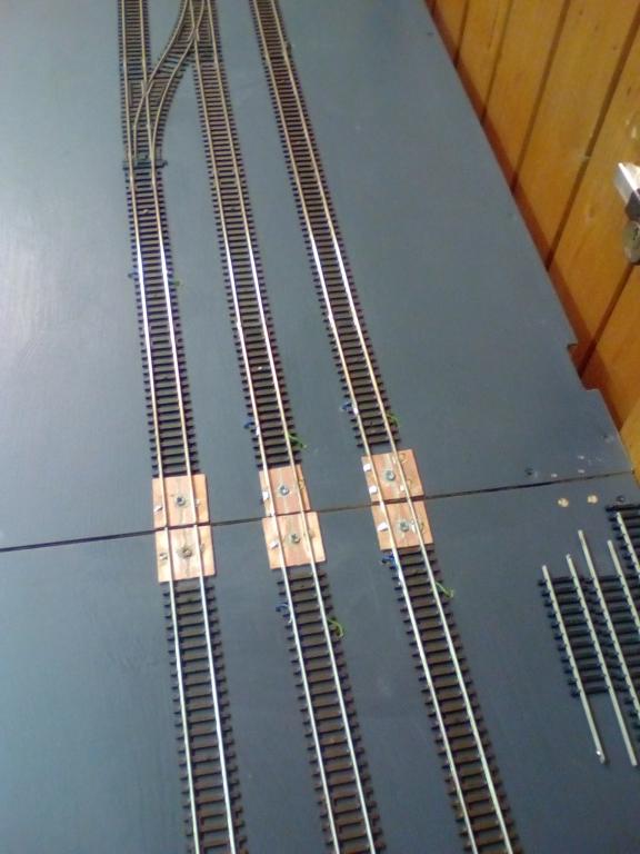
And here are photos of track across the gap complete. Very fiddly but happy with the end result. As you can see i have wired across the gap for continuity and am in the process of wiring a plug and socket 6 way connector.