Paddy Mac Namara
-
Posts
186 -
Joined
-
Last visited
-
Days Won
1
Content Type
Profiles
Forums
Events
Gallery
Blogs
Everything posted by Paddy Mac Namara
-
Thanks murph it's NOCH
-
Thanks for likes and wows.
-
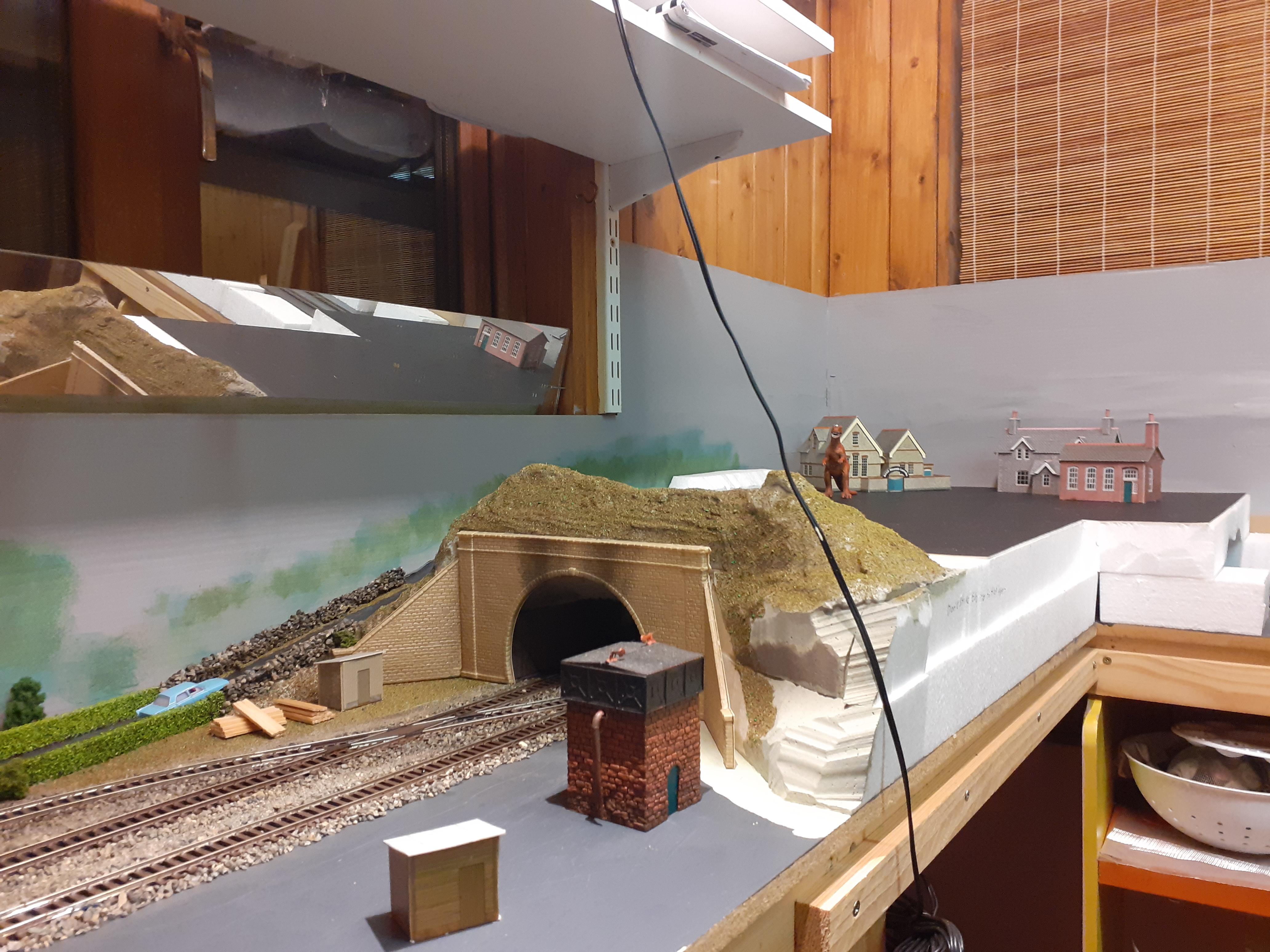
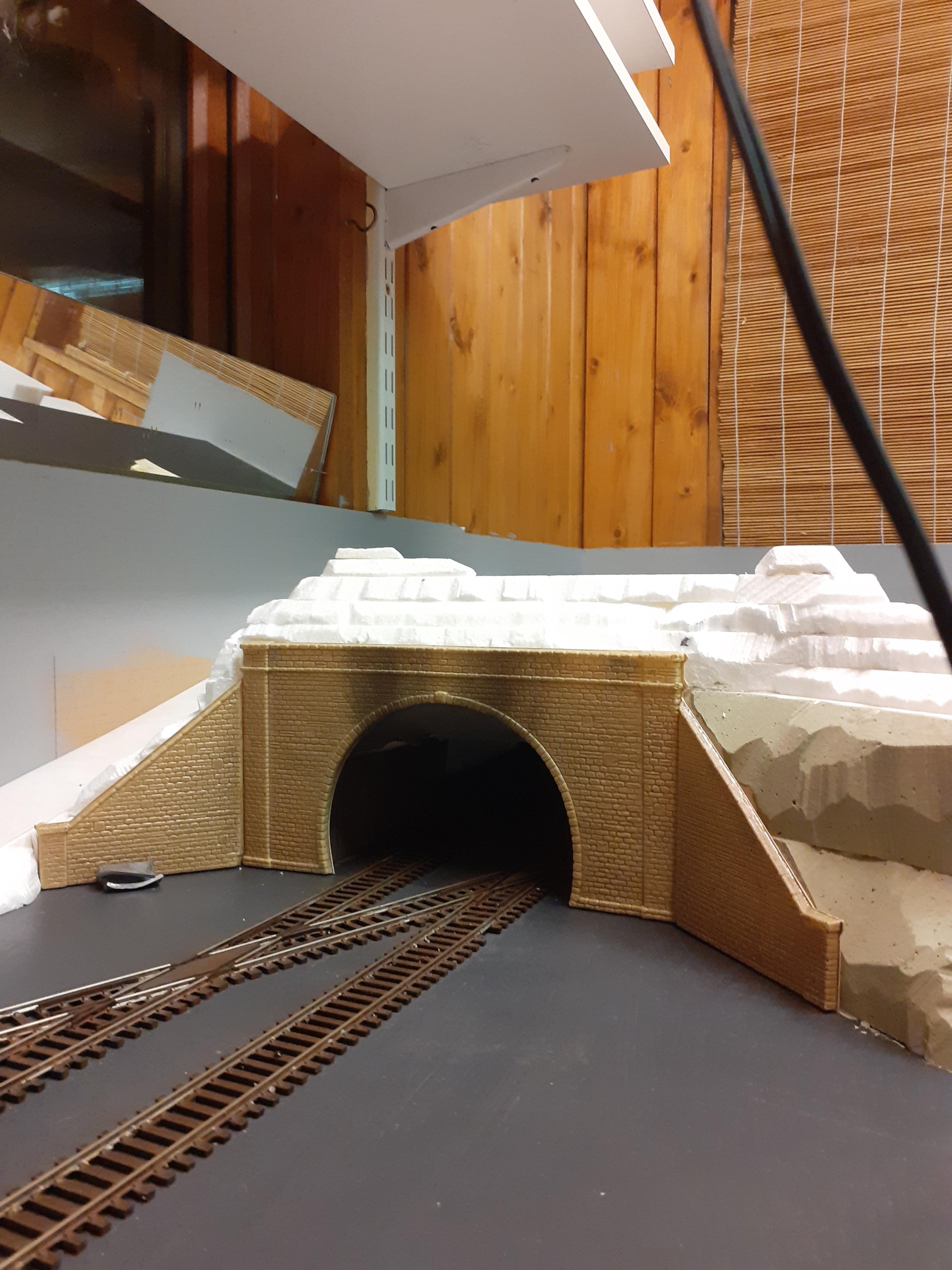
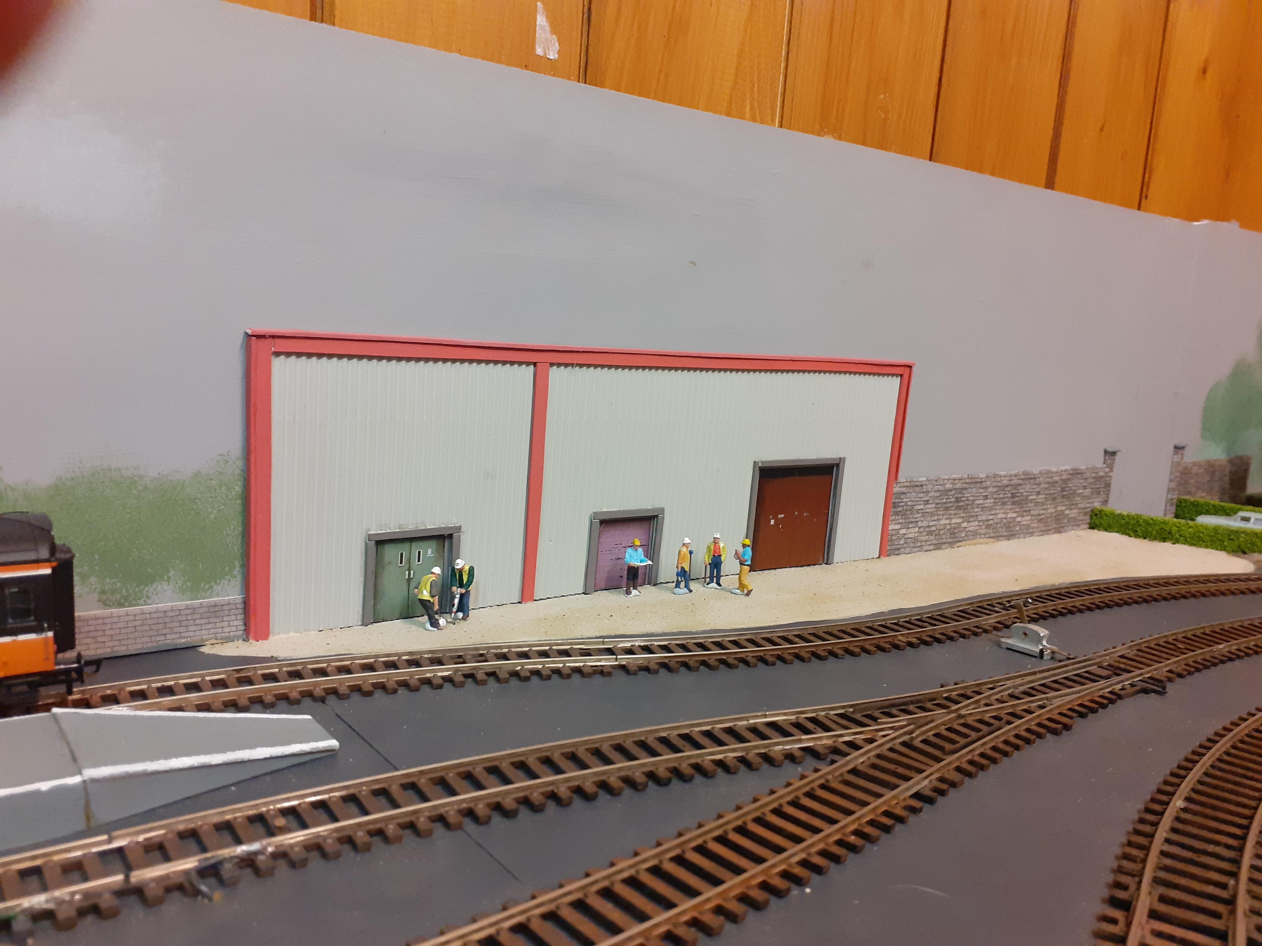
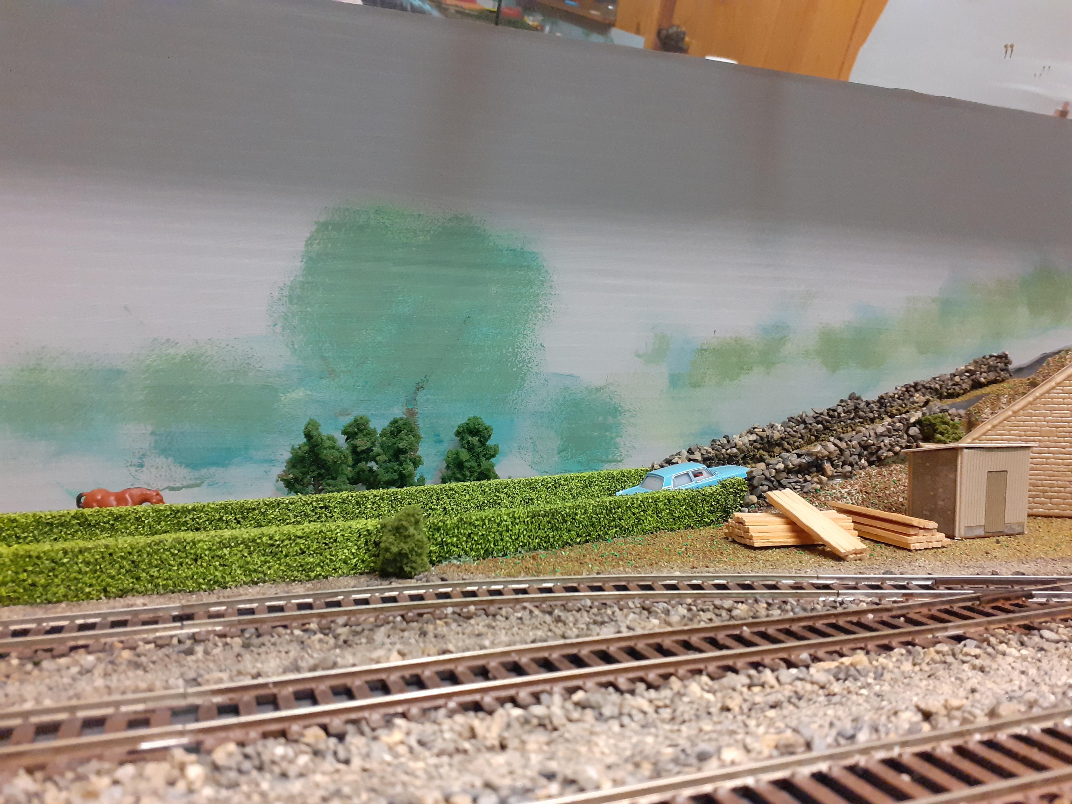
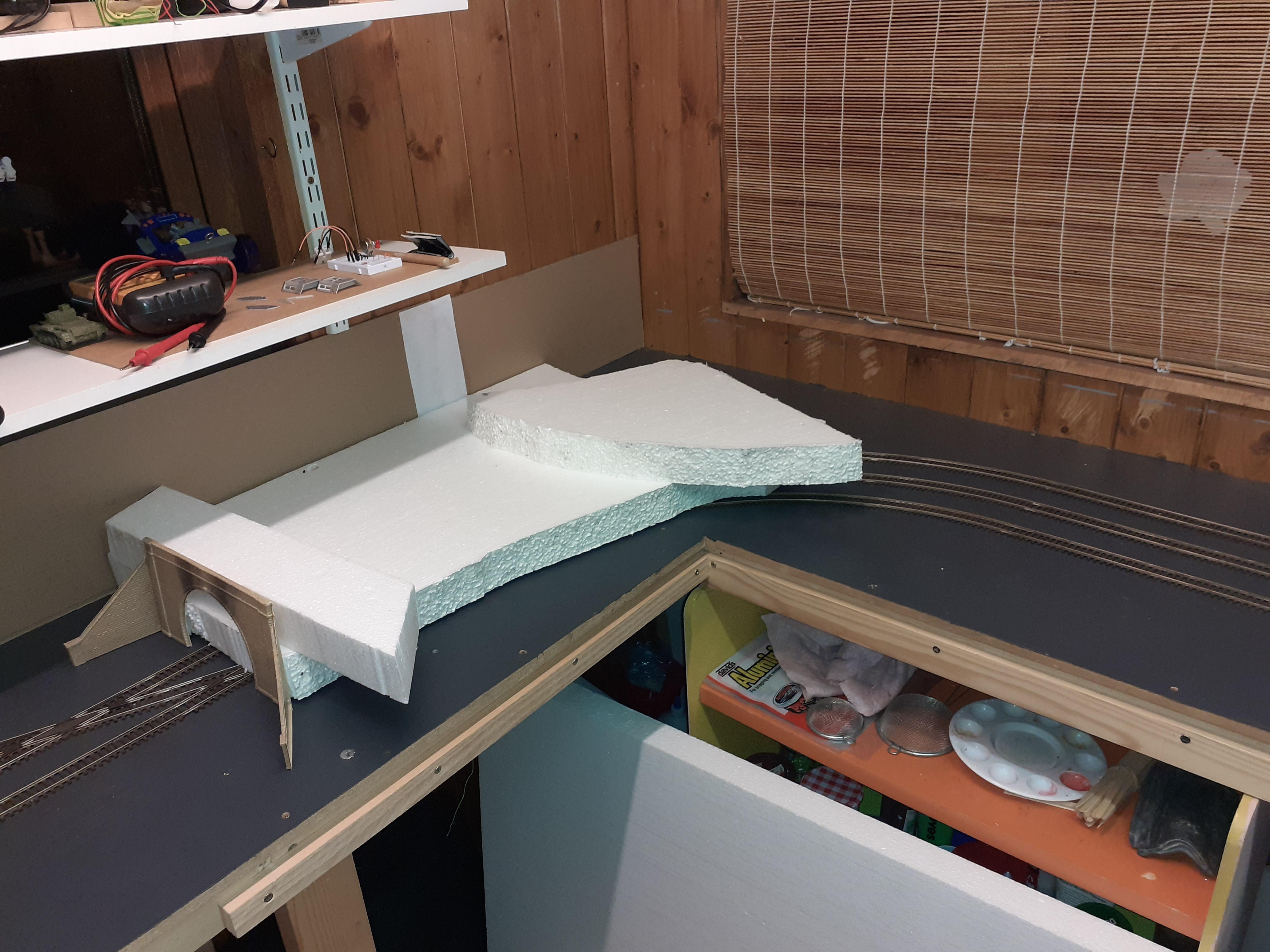
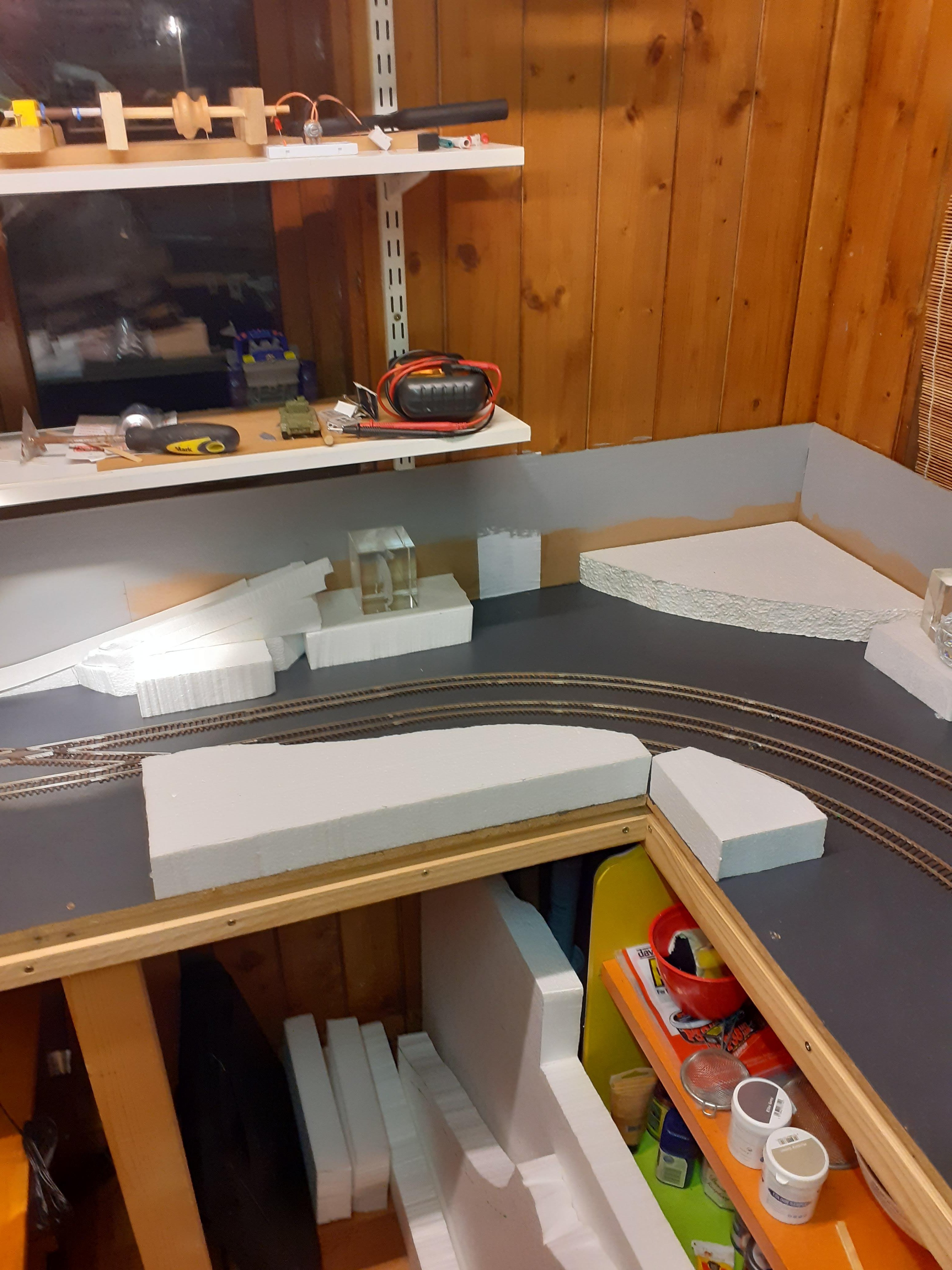
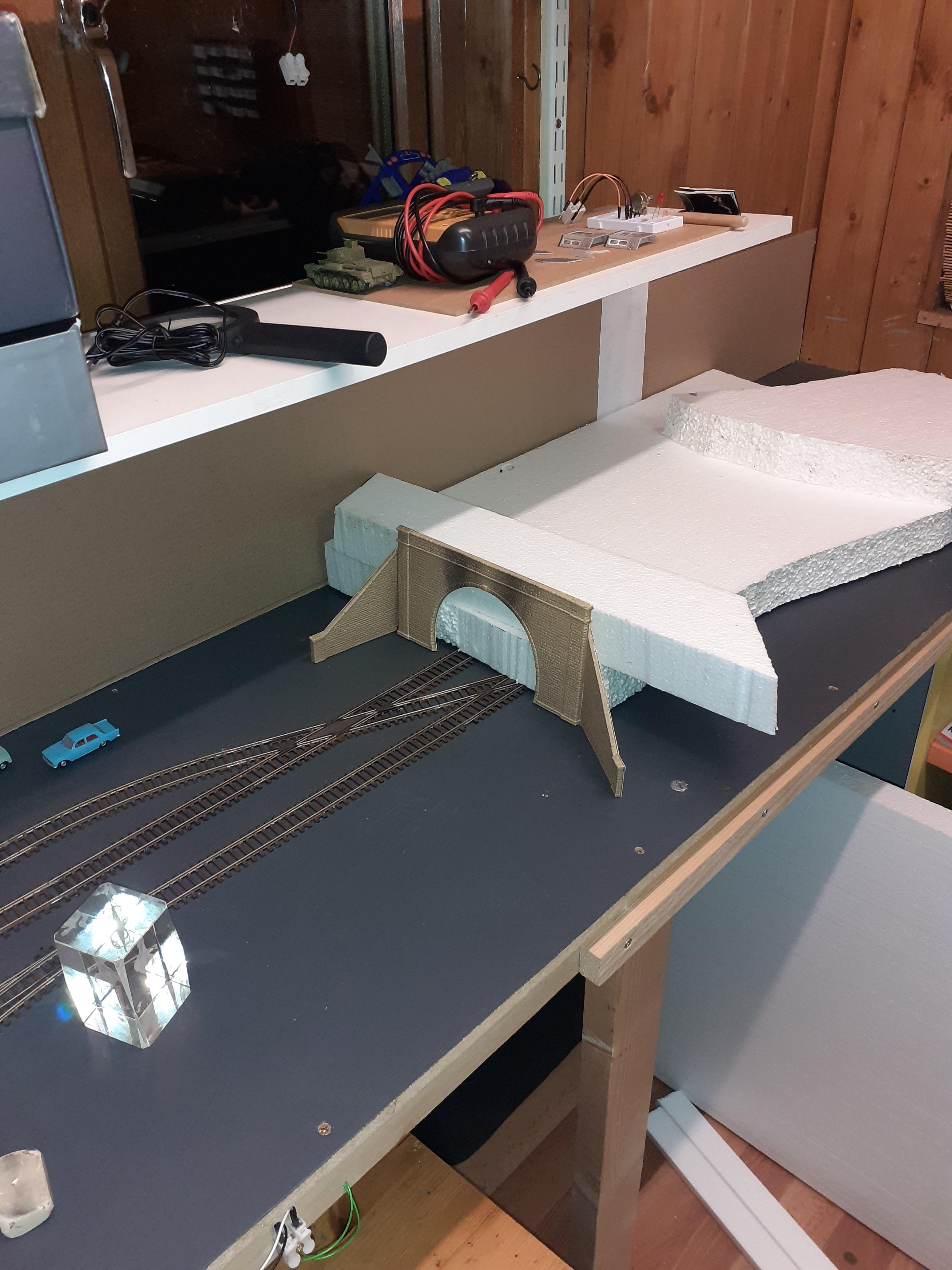
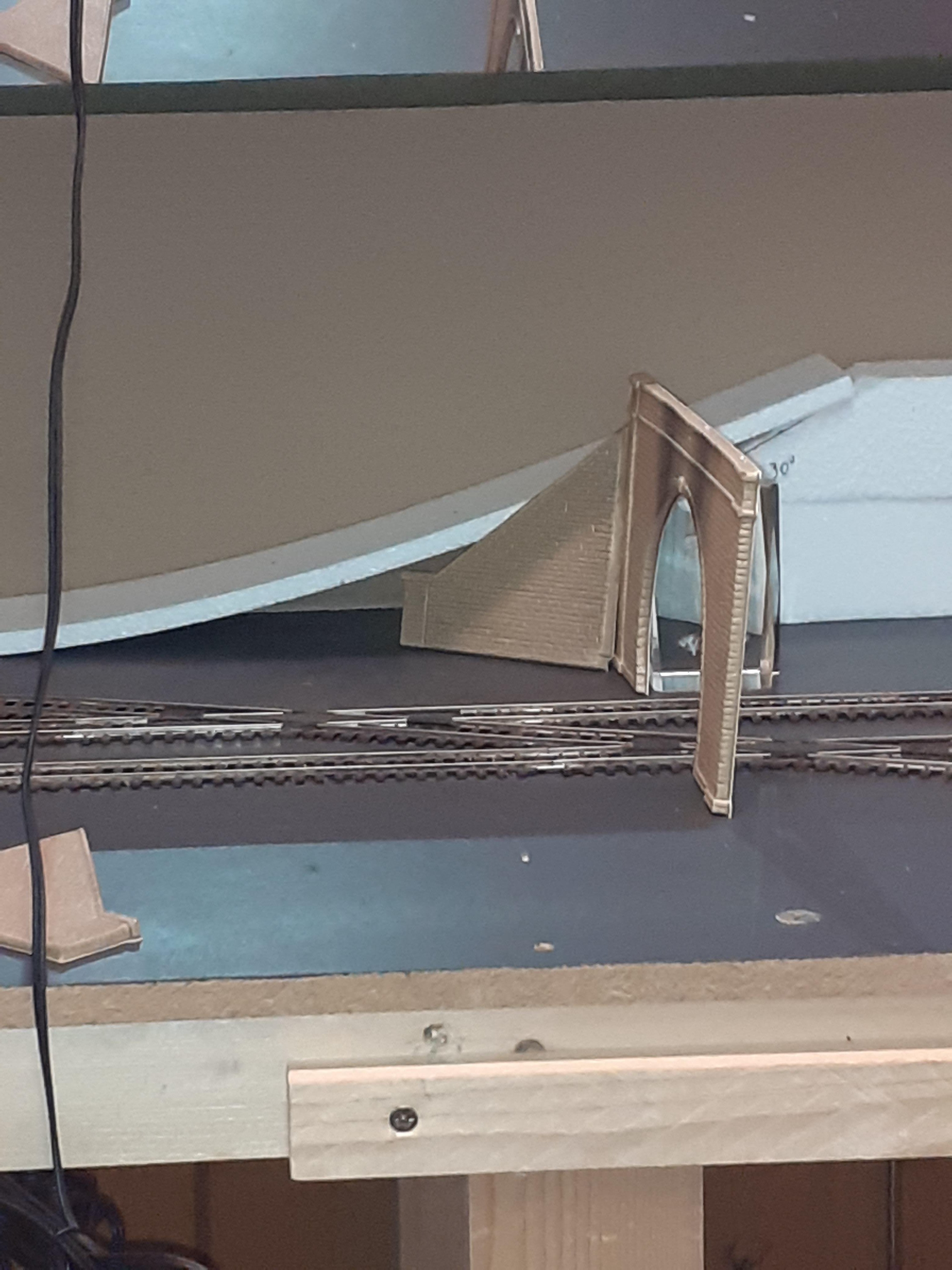
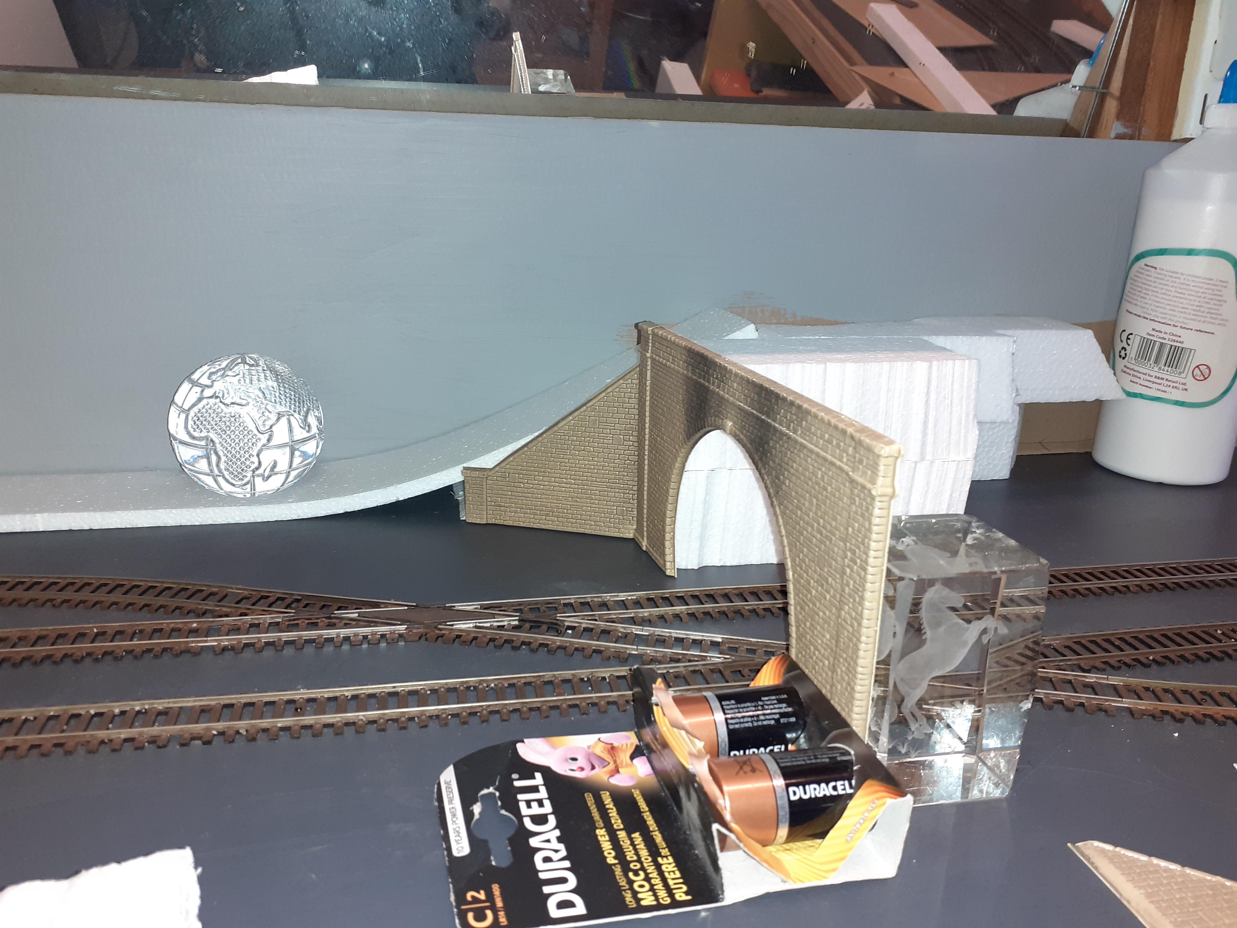
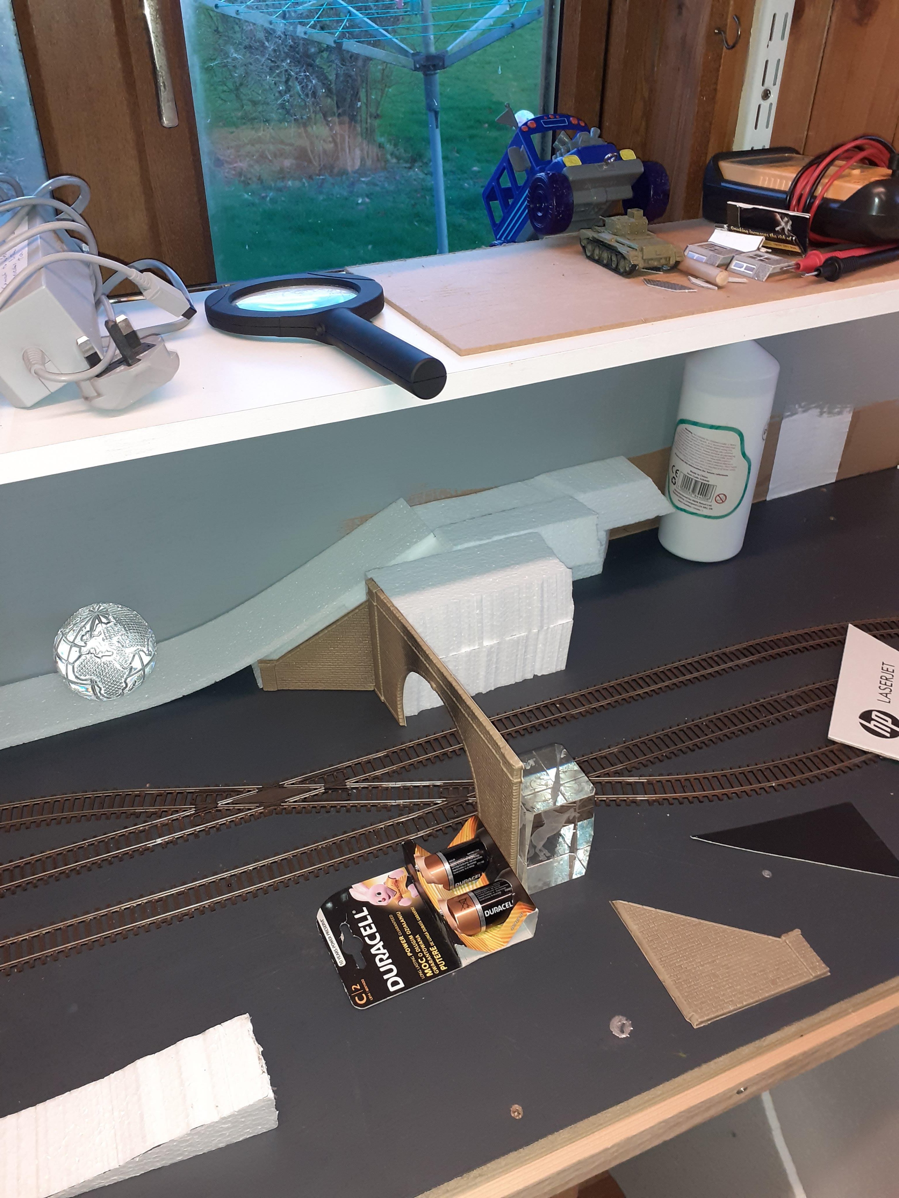
work on tunnel mouth and landscaping and this area on station upside needed attention

- 91 replies
-
- 12
-

-

-
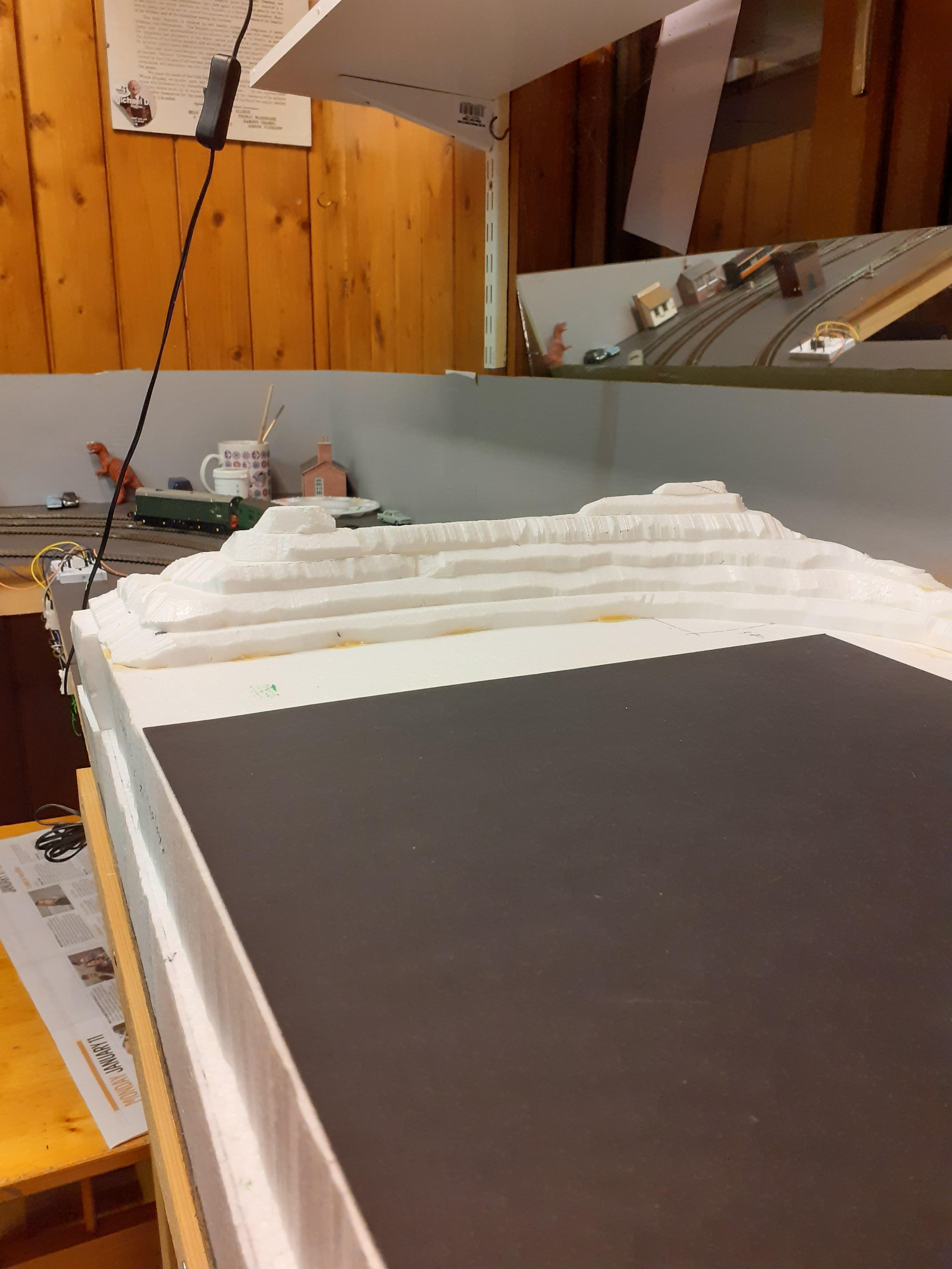
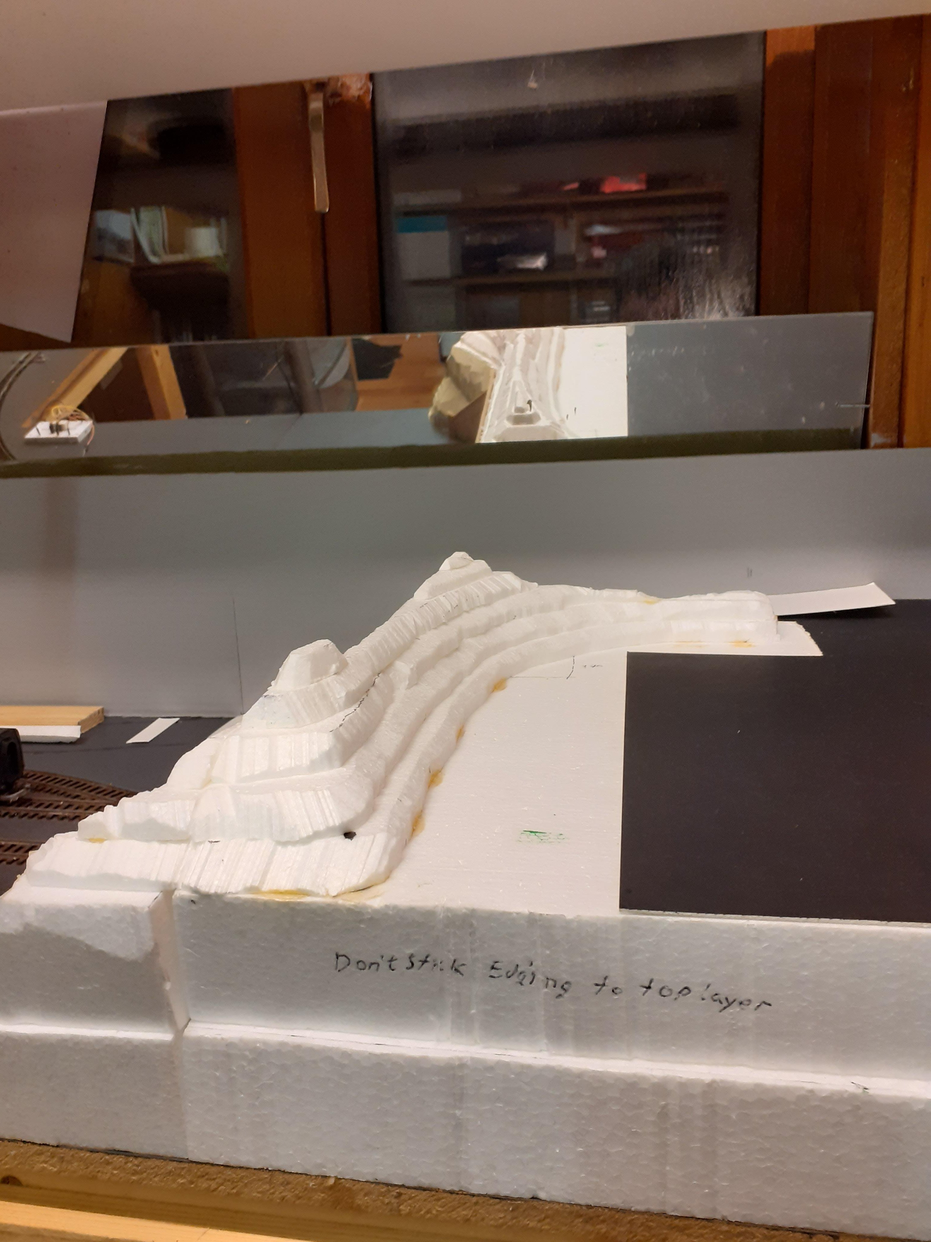
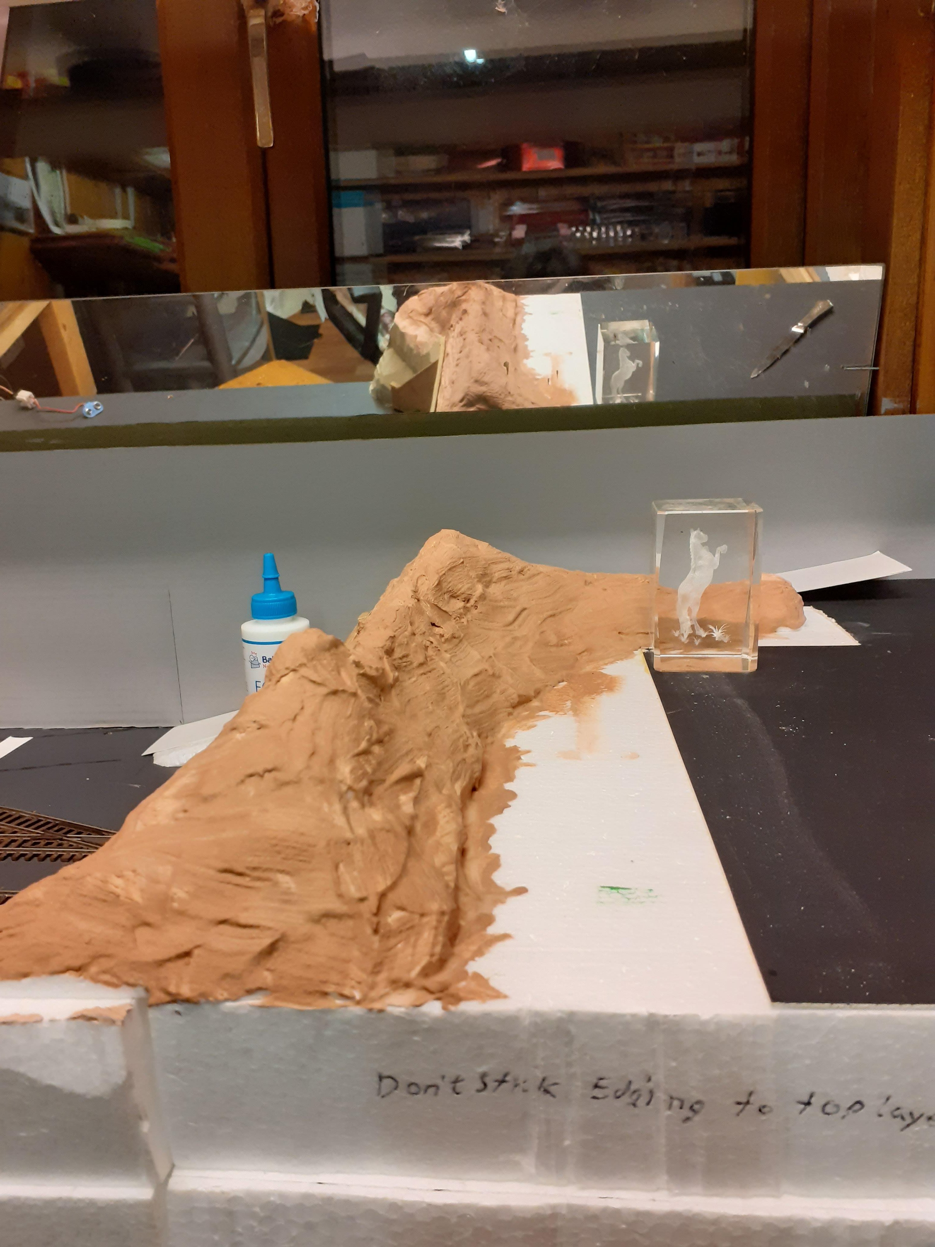
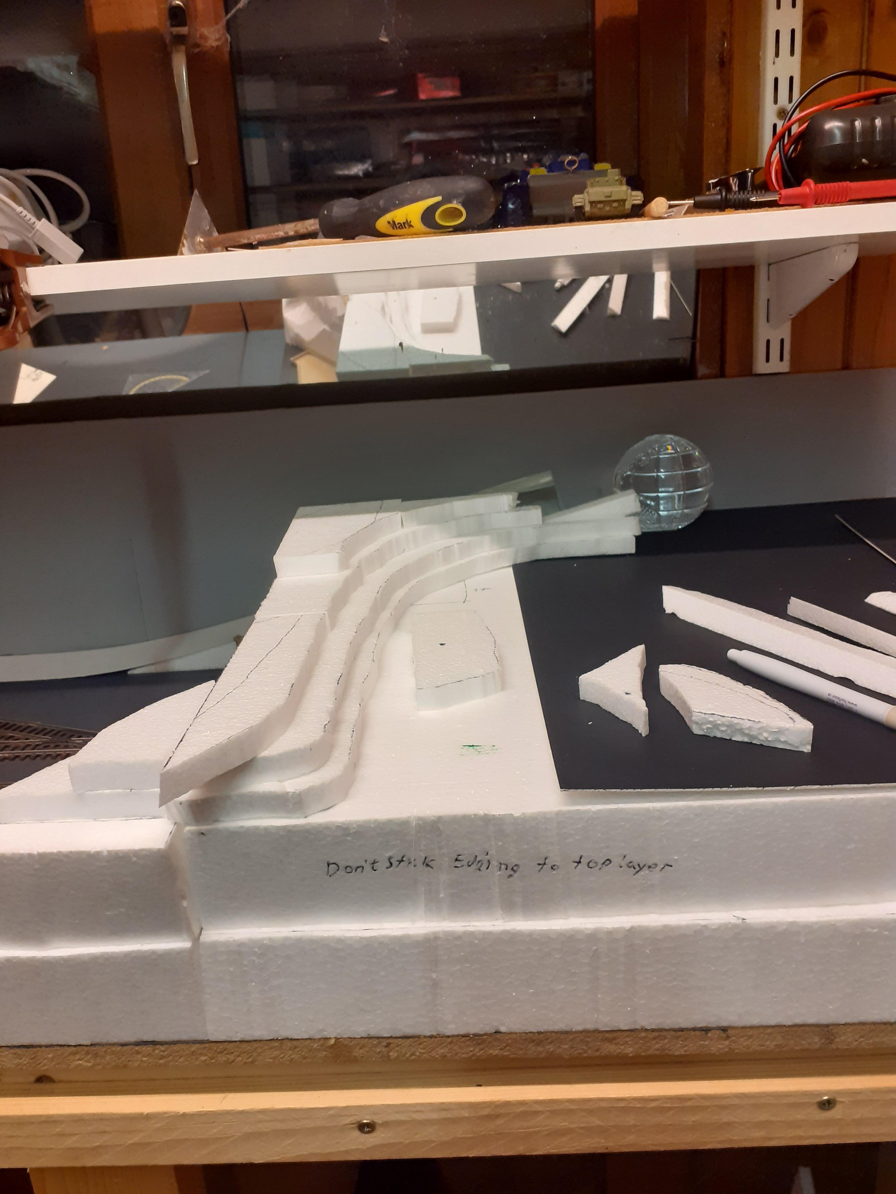
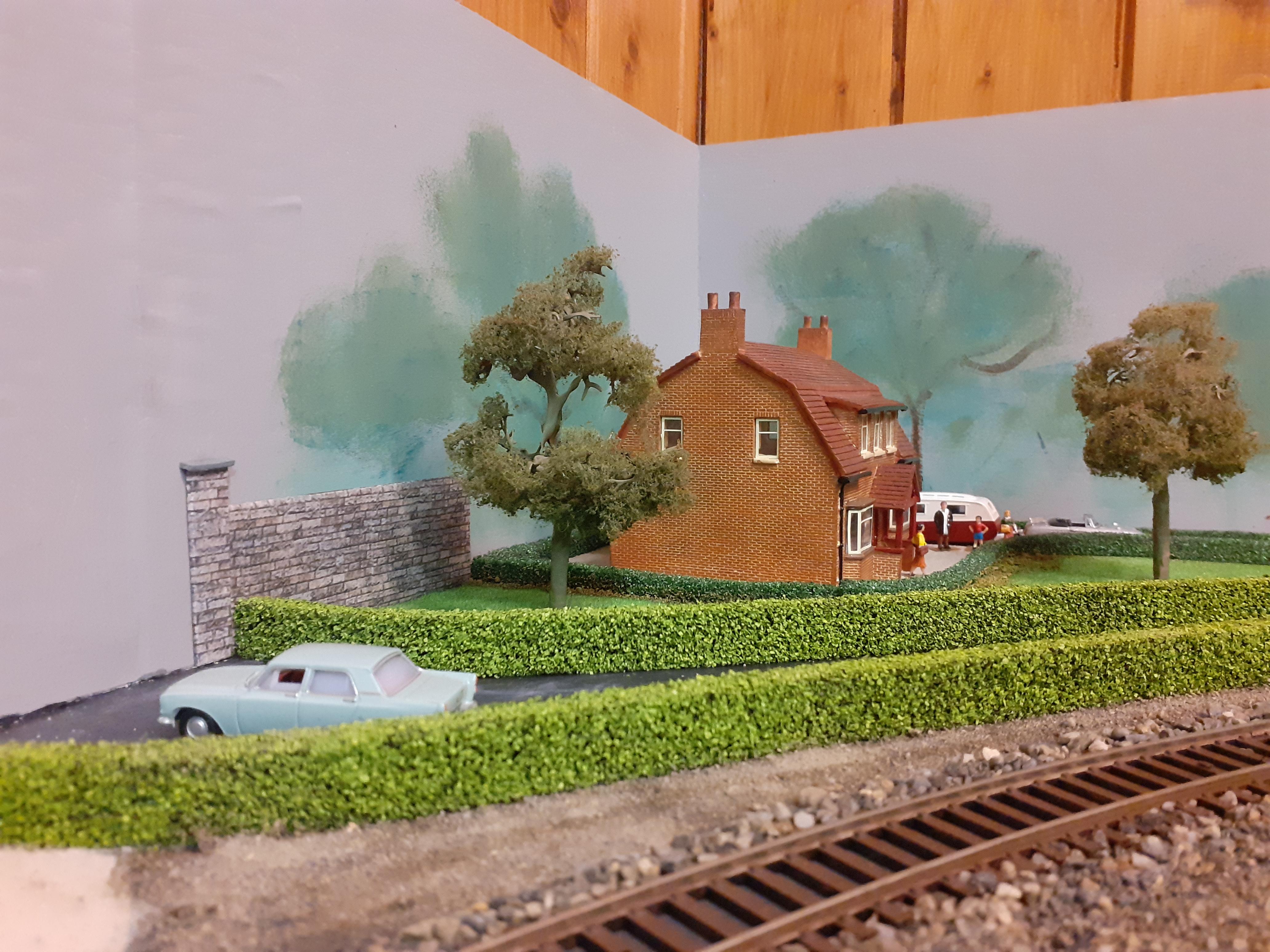
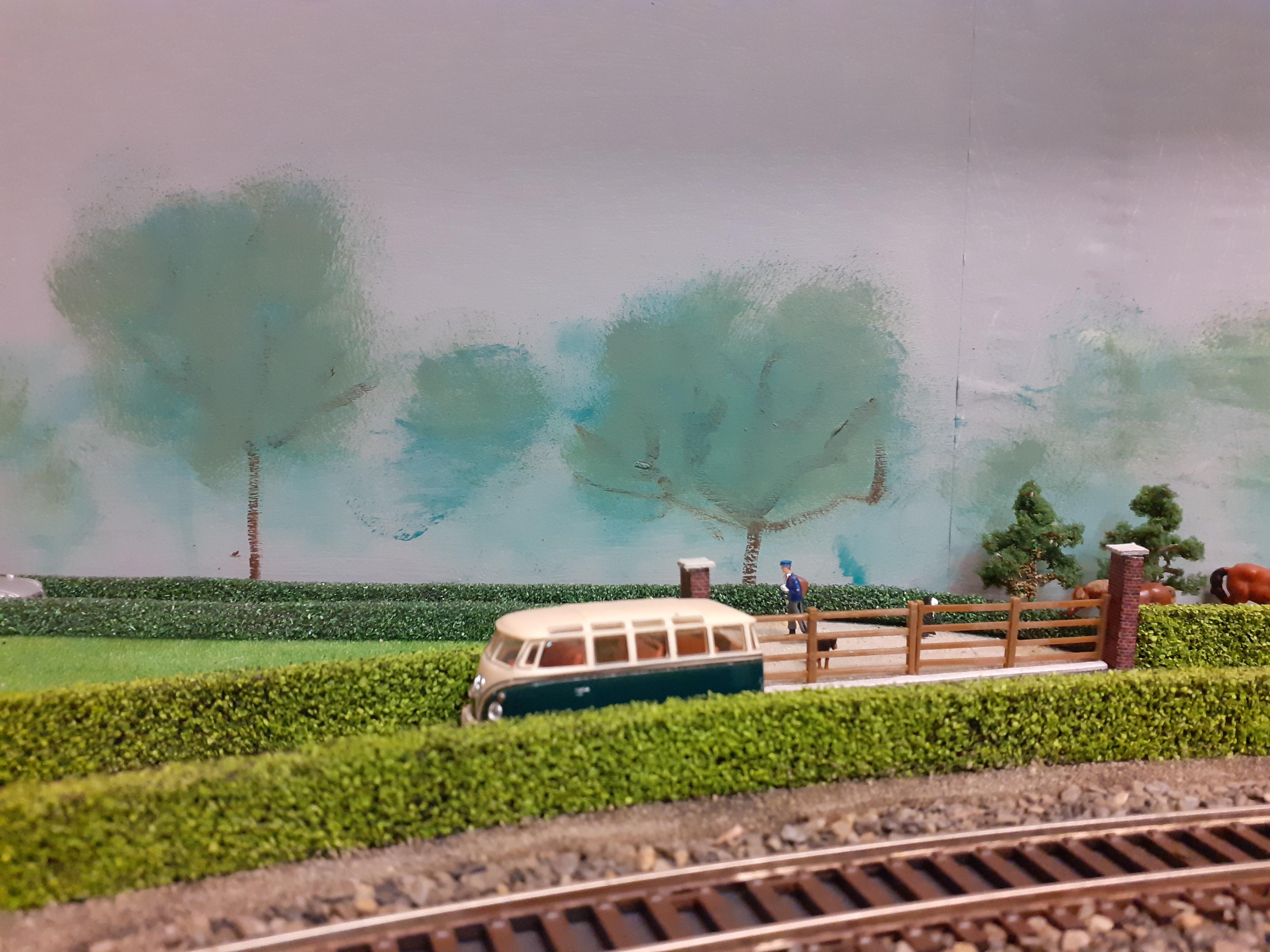
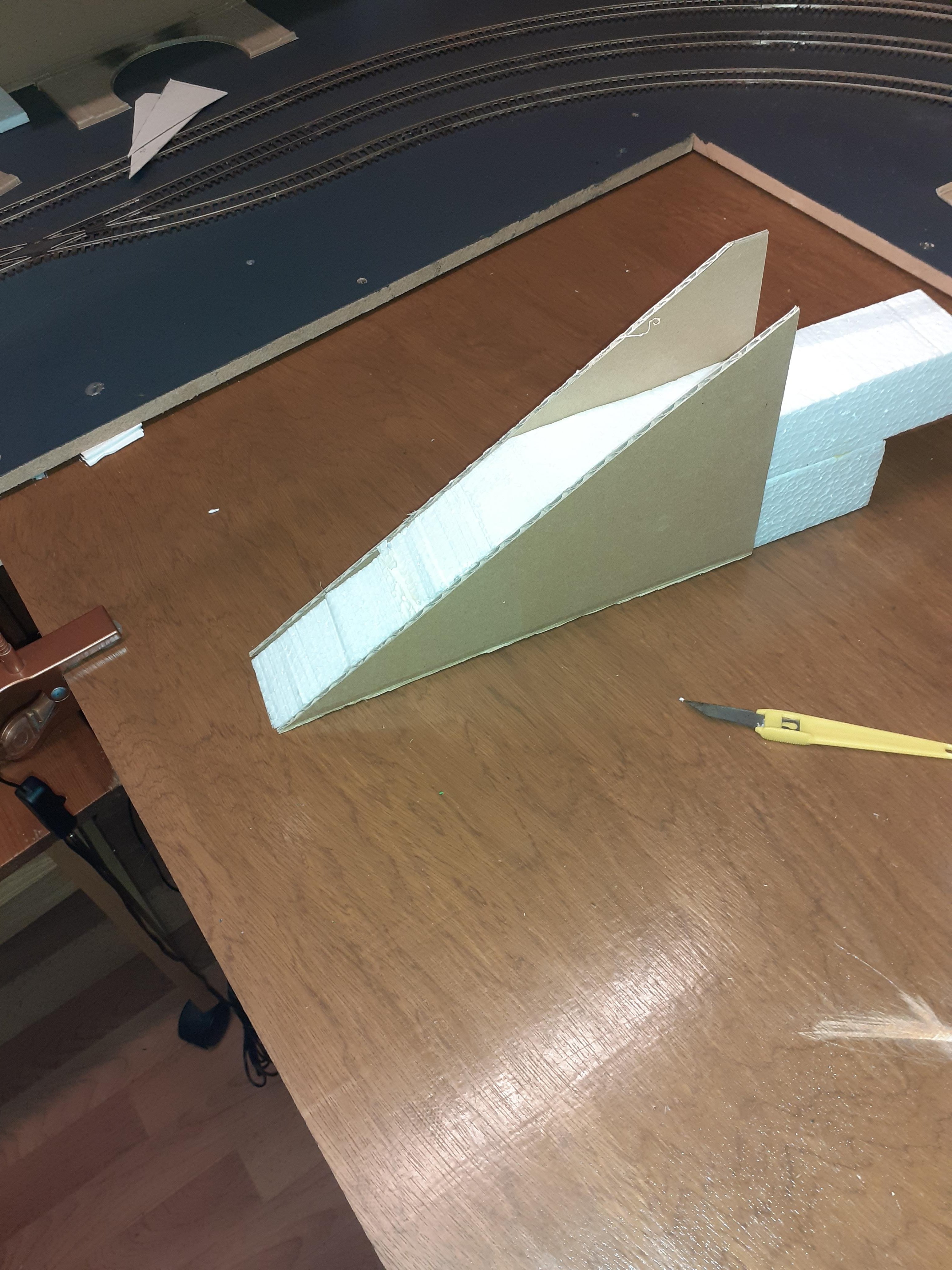
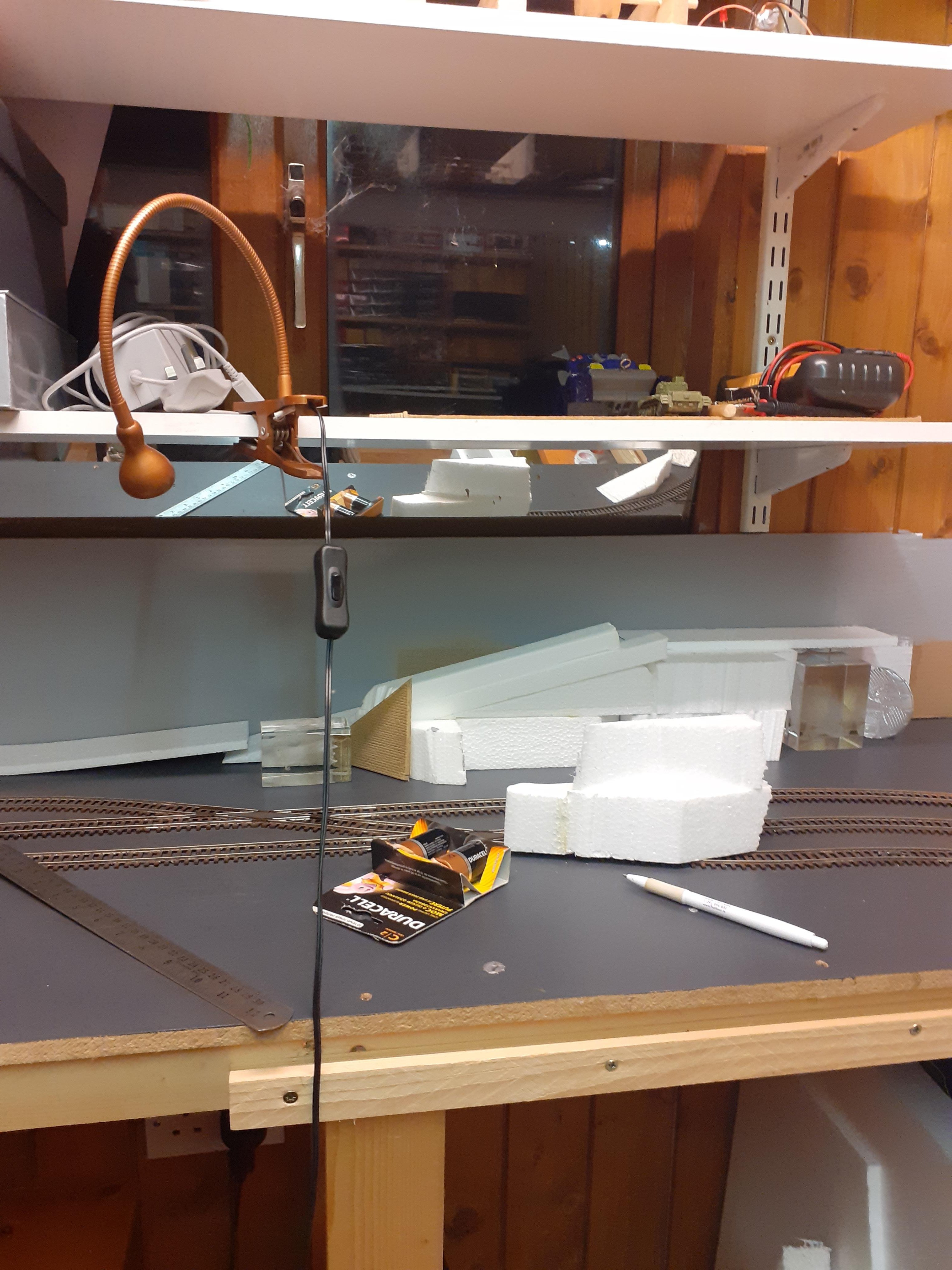
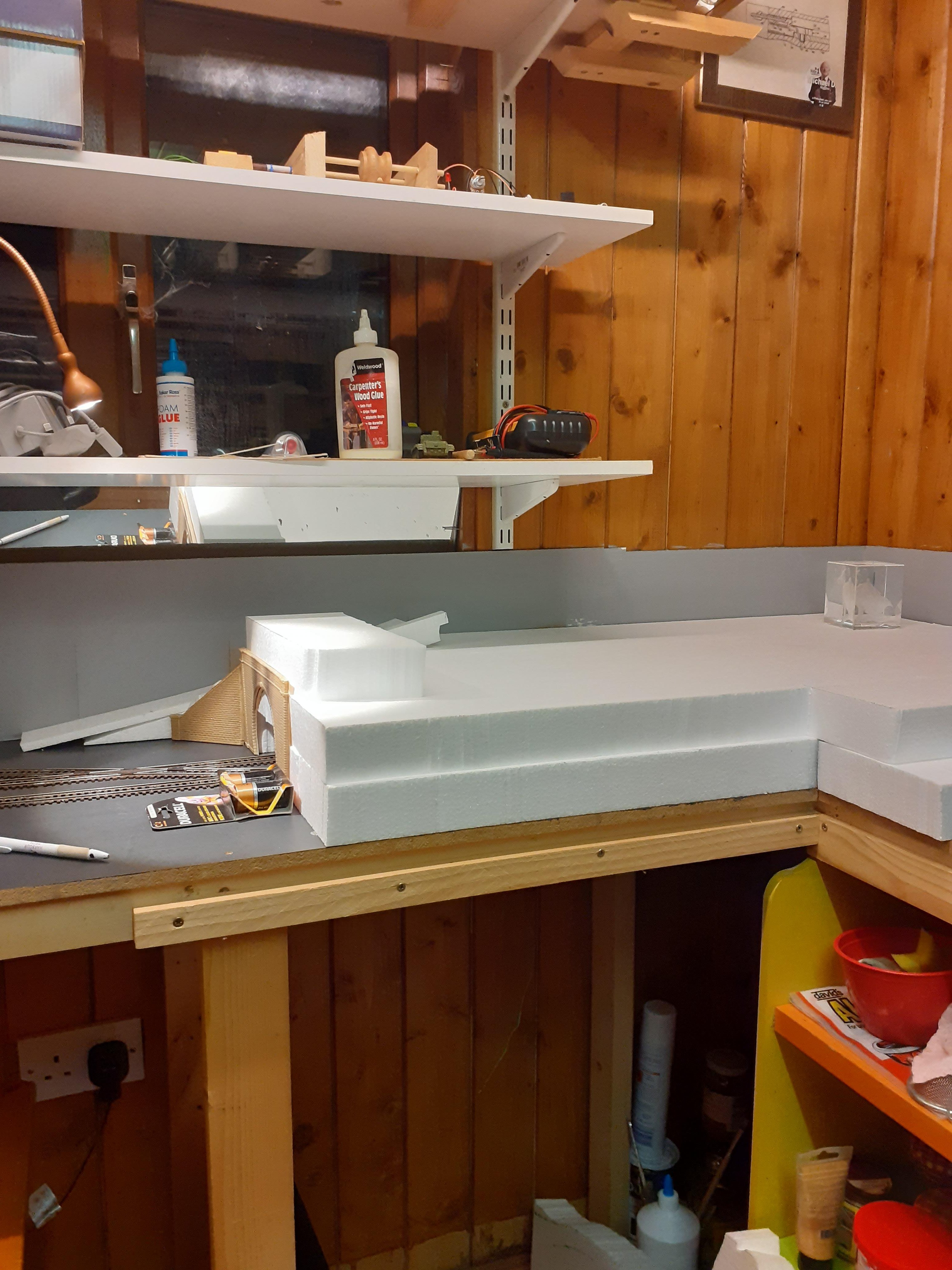
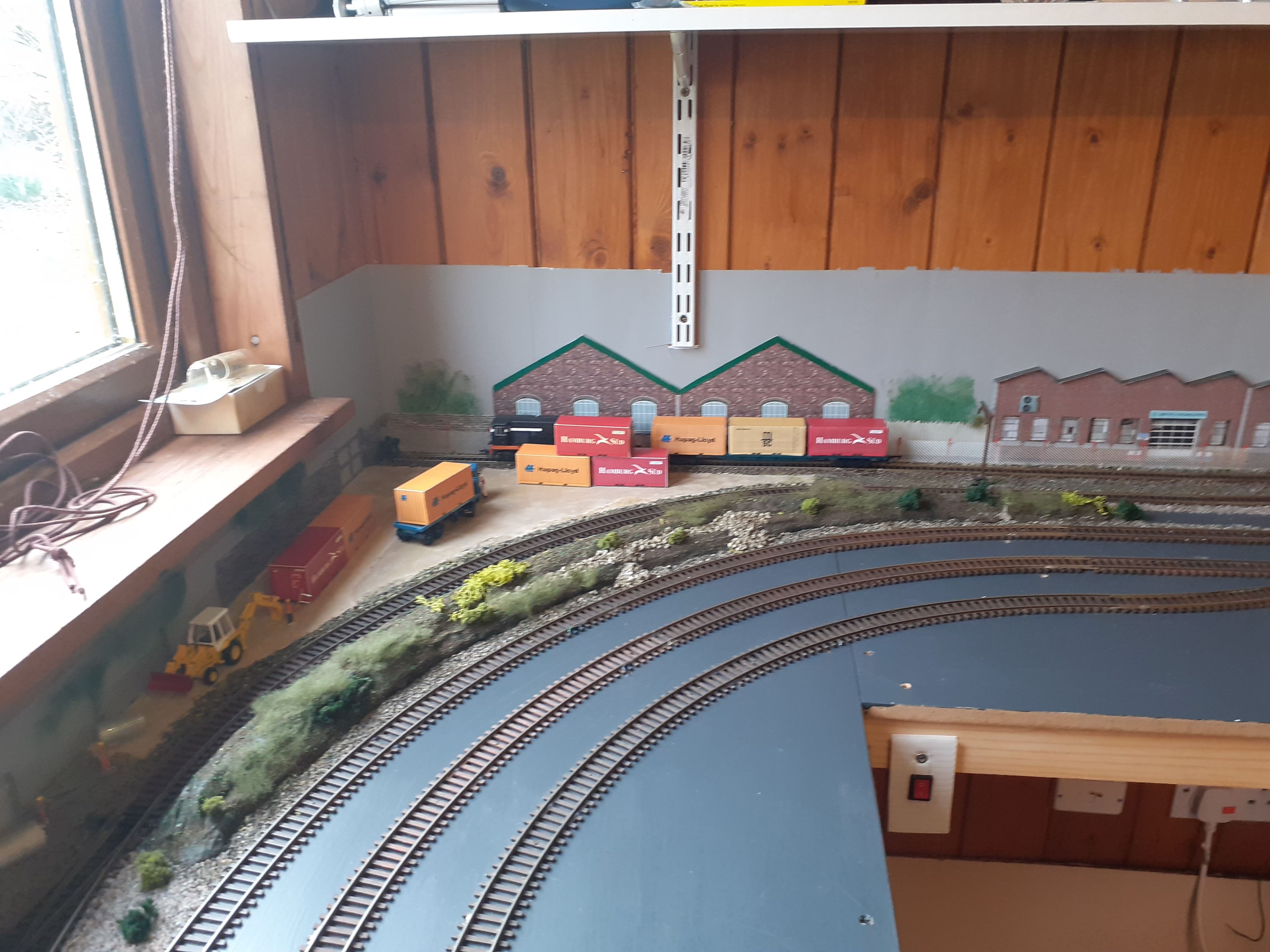
Latest developments, wanted to do something in this corner, so opted for a tunnel and this will allow me to create more landscape on top and town/village scene spent a good bit of time just thinking about how i would do the road ramp
-
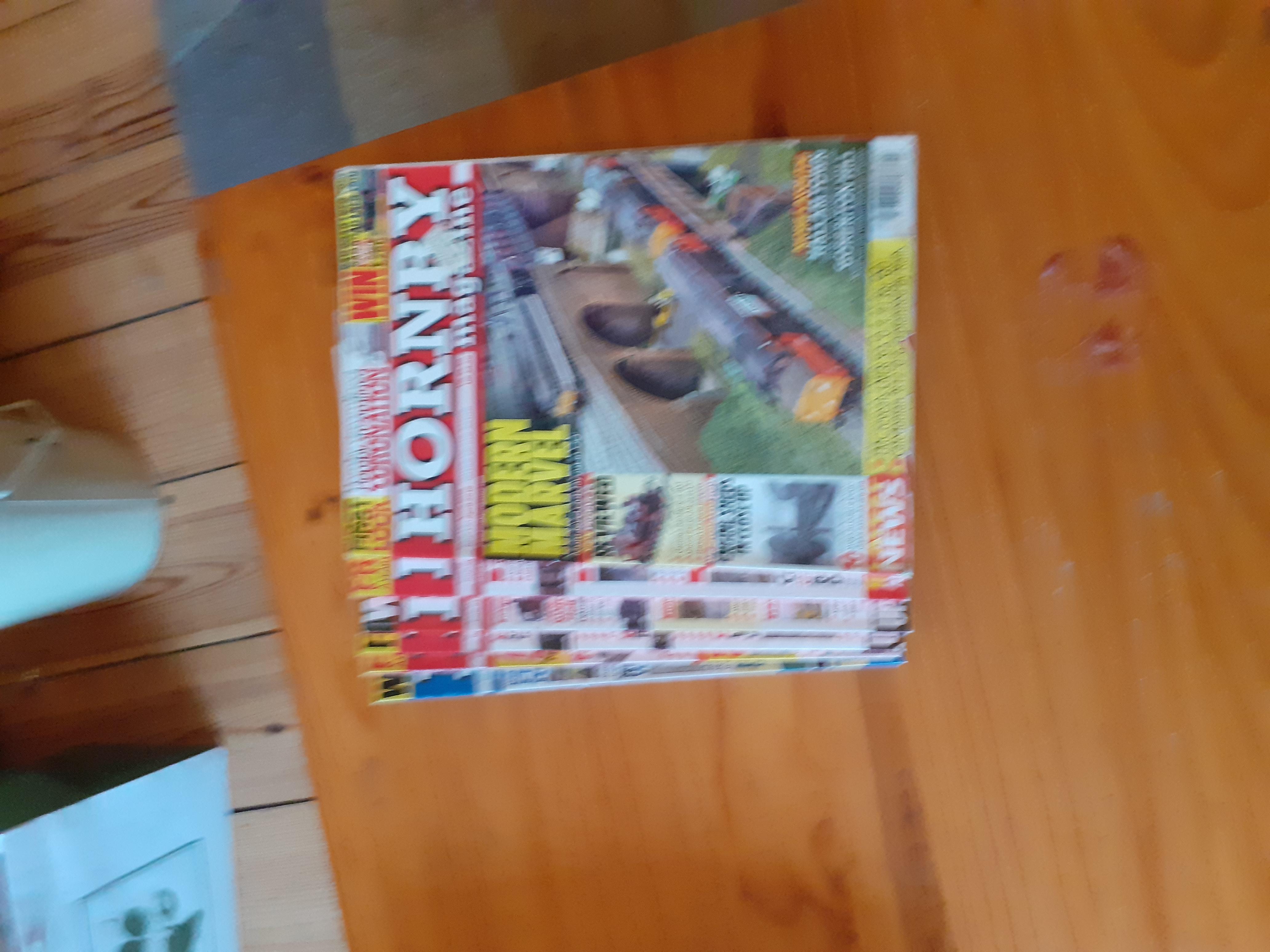
Magazines and catalogues
Paddy Mac Namara replied to Paddy Mac Namara's topic in Free to a good home
Hi Pat, Sorry they are promised to someone else, who is going to pick them up after lockdown -
I live in sallins near naas, if you want to collect them
-
Diamond Crossing Protector
Paddy Mac Namara replied to Paddy Mac Namara's question in DCC, Electrics and Electronics
Thanks noel for your words of encouragement. Not sure if i understand the question, i am detecting the loco on the "mainline", but there are loads of operation issues, its a solution, not a complete one. For example if a "branchline" loco is already in the junction. the "mainline" loco will switch of power to the branchline loco and its stuck there so we have a crash. Because the layout is continuous and i have an identical junction on the other side, once both junctions are protected, the branchline locos will always lag the mainline loco, so collisions should be avoided. a fail-safe solution, whilst possible, just gets way too complicated i'd spend my life under the layout wiring it all up. I may come back to it in the future, but for the moment i have loads of scenic modelling to do -
Diamond Crossing Protector
Paddy Mac Namara replied to Paddy Mac Namara's question in DCC, Electrics and Electronics
hi sven, i went with the reed switch, i posted video on "Celbridge" thread on layout forum. Yep you are right, Photo transistor is sensitive to ambient conditions but you can adjust sensitivity with resistor, with limitations, i have done quite a bit on this and if you check out my youtube channel you can see for your self. Name of channel is Patrick Mac Namara. Here's a longer (winded) version with maybe clearer explanation on real track with the reed switches. -
Thanks MikeO really appreciate the encouragement
-
So i decided to bite the bullet and try out the diamond crossing protector on the layout with actual locomotives.
-
Diamond Crossing Protector
Paddy Mac Namara replied to Paddy Mac Namara's question in DCC, Electrics and Electronics
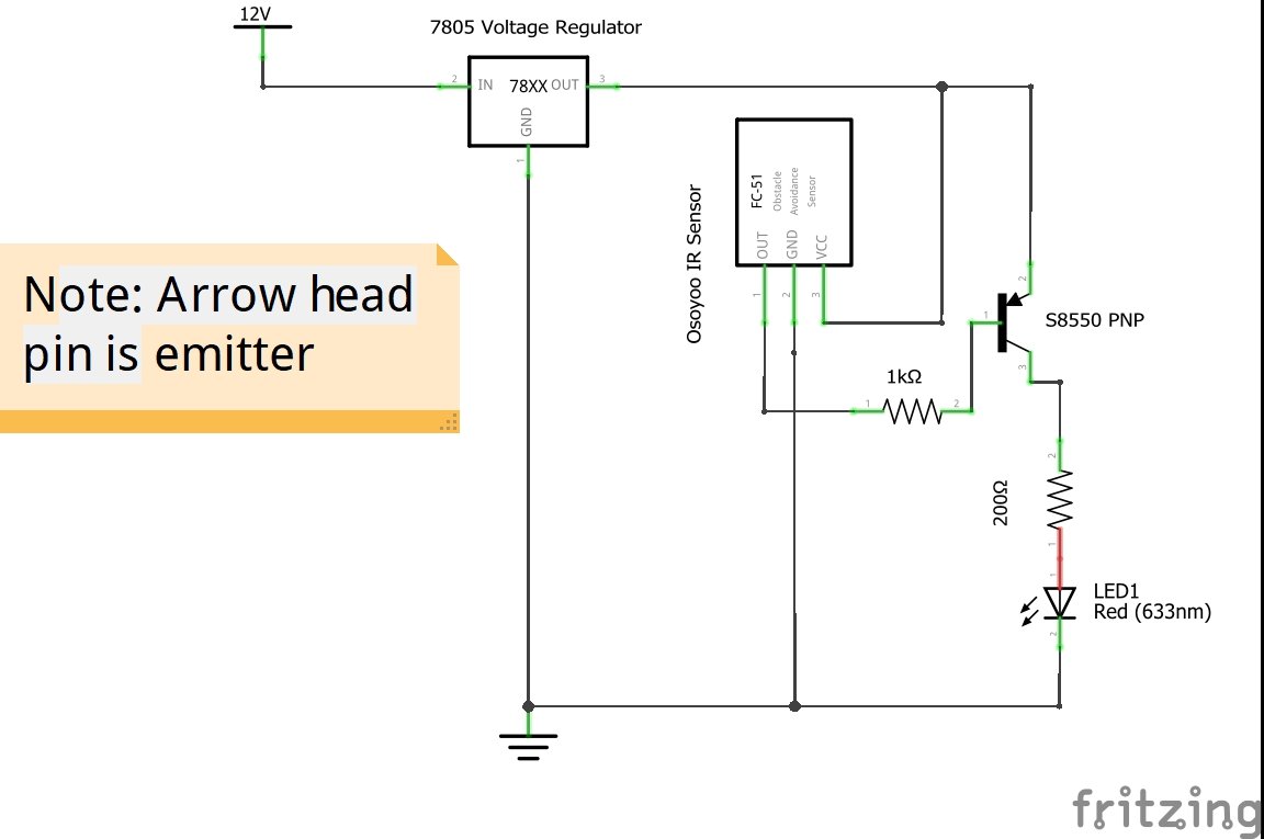
This video is doing pretty much the same thing as the one above and uses the same code for the Arduino, but in this demo i am using Phototransistors. -
Diamond Crossing Protector
Paddy Mac Namara replied to Paddy Mac Namara's question in DCC, Electrics and Electronics
Got some IR sensors and have been playing around with them and Arduino micro-controller. -
Just a quick video to show how Infra Red sensors work for detecting locomotives. I'll post a more detailed video on the electronics forum for those who may be interested.
-
Diamond Crossing Protector
Paddy Mac Namara replied to Paddy Mac Namara's question in DCC, Electrics and Electronics
I've been doing some experiments with phototransistors as a means of detecting locos. -
Diamond Crossing Protector
Paddy Mac Namara replied to Paddy Mac Namara's question in DCC, Electrics and Electronics
-
i like this little layout, my advice keep it simple for your first layout, also i'm shocked you left the mechanical engineering brotherhood to go to the dark arts of software.
-
i'm not a great fan of the "emoji" likes, so here's some real words. "i like". track plans etc...?????
-
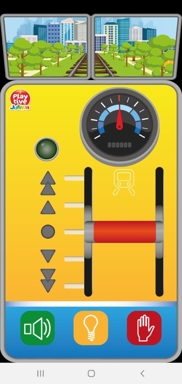
got a new loco for the layout, the scale maybe a bit of but it's dcc
-
Diamond Crossing Protector
Paddy Mac Namara replied to Paddy Mac Namara's question in DCC, Electrics and Electronics
Thanks Dhu, could you share some detail on this detection circuit, photos, circuit diagram, list of parts? cheers paddy mac -
Diamond Crossing Protector
Paddy Mac Namara replied to Paddy Mac Namara's question in DCC, Electrics and Electronics
hi sven, thanks for your comments and interest. I don't think that will be a problem, my previous experiments, see vid from 10th march 2019, show that the magnet does engage reed switch when attached to loco, in fact the magnet is very close to the switch as it passes over. What i was more concerned with is the double contact of reed switch as the magnet passes over it as shown in the video below. When using the Arduino and coding this was a problem and that is why there is a time delay in the code, so that the code ignores the second contact. With this circuit as long as the magnet passes over the reed switch reasonably quickly, the charging and discharging of the capacitor takes time so the second contact does not cause a problem. According to this site it takes 0.25 sec to full charge.https://www.allaboutcircuits.com/tools/capacitor-Charge-and-time-constant-calculator/ -
Diamond Crossing Protector
Paddy Mac Namara replied to Paddy Mac Namara's question in DCC, Electrics and Electronics
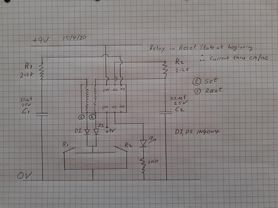
As shown above the circuit using the Arduino allows for control of the junction with a loco going both ways. In my post of 10th march 2019 i could only get control in one direction using relays only and i have been trying to solve this for a year...Despite my best efforts i could not devise my own solution, however i came across the solution below recently and it is very satisfactory. more detail on how the circuit works: The initial state for this circuit is relay in Reset State. Thus the relay armatures are connected to cm-nc. The led is lit up, the led represents power to track you wish to isolate. Capacitor C2 charges up to +9V via 2.2k resistor R2 while capacitor C1 remains discharged as it is not connected to the 9V supply. If reed switch R1 or R2 is activated,C2 discharges via the relay’s “set” coil 2 and diode D2.This switches the relay into its set position, thus relay armature are connected to cm-no, the LED will switch off. C1 then begins to charge via R1. While R1 or R2 are activated the relay does not return to the reset position because the current supplied via R1 is insufficient for the coil to latch the armature. Once the relay has switched and C1 has finished charging, activating R1 or R2 again causes the relay to switch back to the reset state via coil 1 and the LED comes on again. The relay is a two coil 5v latching relay: Hongfa HFD2 005 M L2 D Bi-stable Latching Relay DPDT 5v, 2 coil, 2A. Purchased on ebay around €2.50/3.00 Capacitors are : Rubycon Electrolytic Capacitor, Miniature, 22 µF, 25 V, ZLG Series, ± 20%, Radial Leaded, 5 mm. These were purchased from Farnell and cost 10cent each Diodes I had in my electronics box, these only cost a few cent. Resistors I got an assortment pack on ebay of 300 with a range of different resistance values, cost was €5. The website I found this circuit on is: https://www.eeweb.com/extreme-circuits/momentary-switch-teamed-with-latching-relay
-
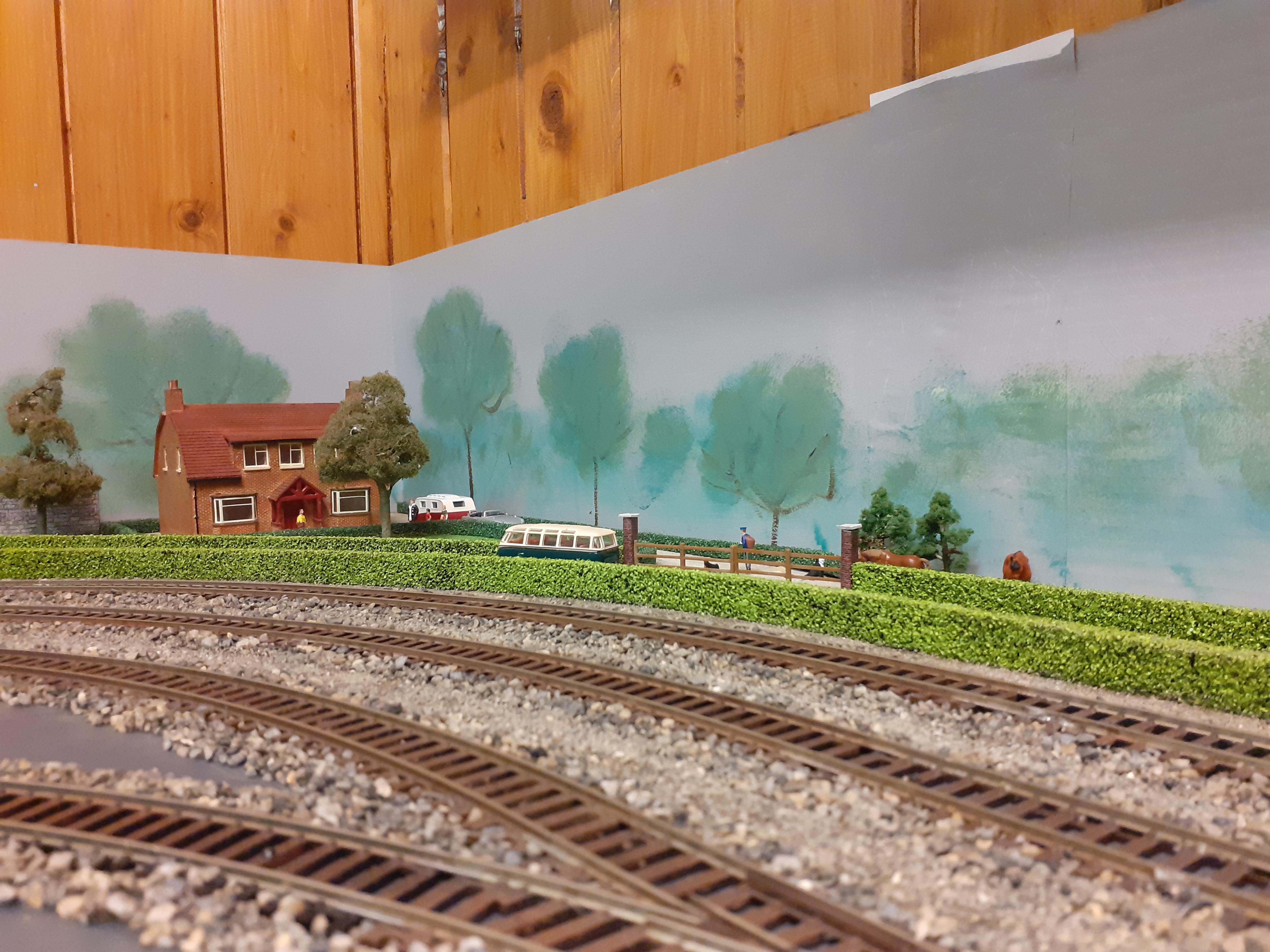
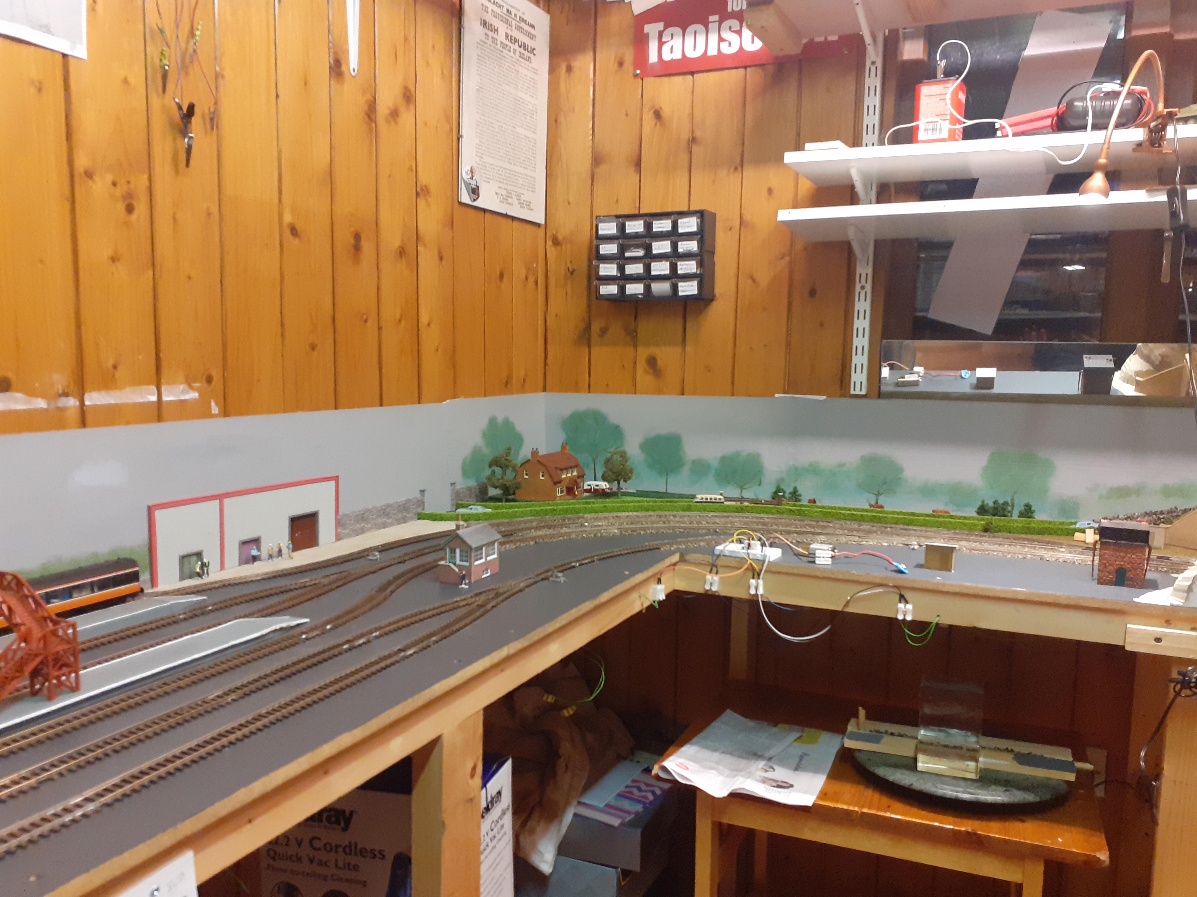
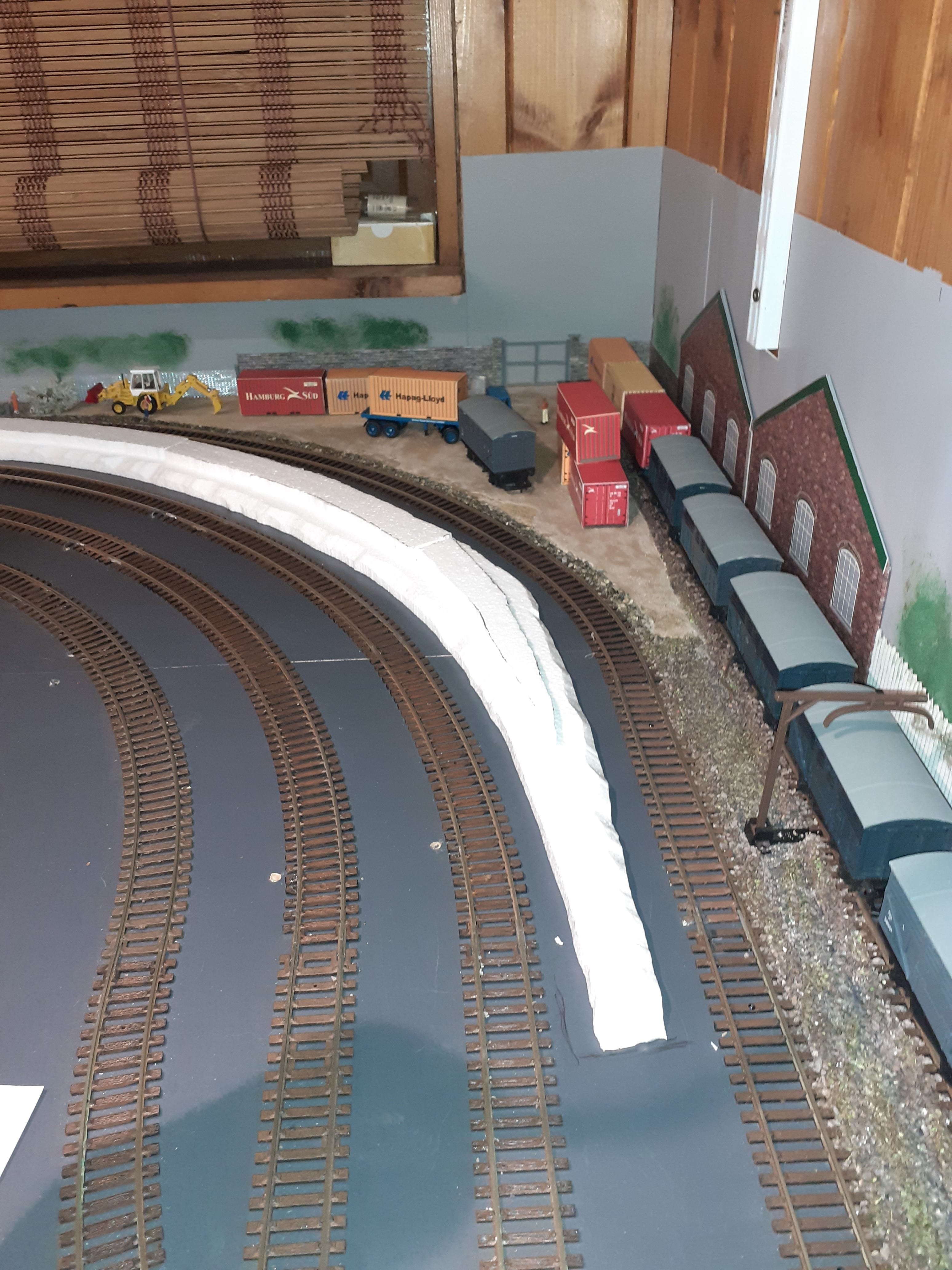
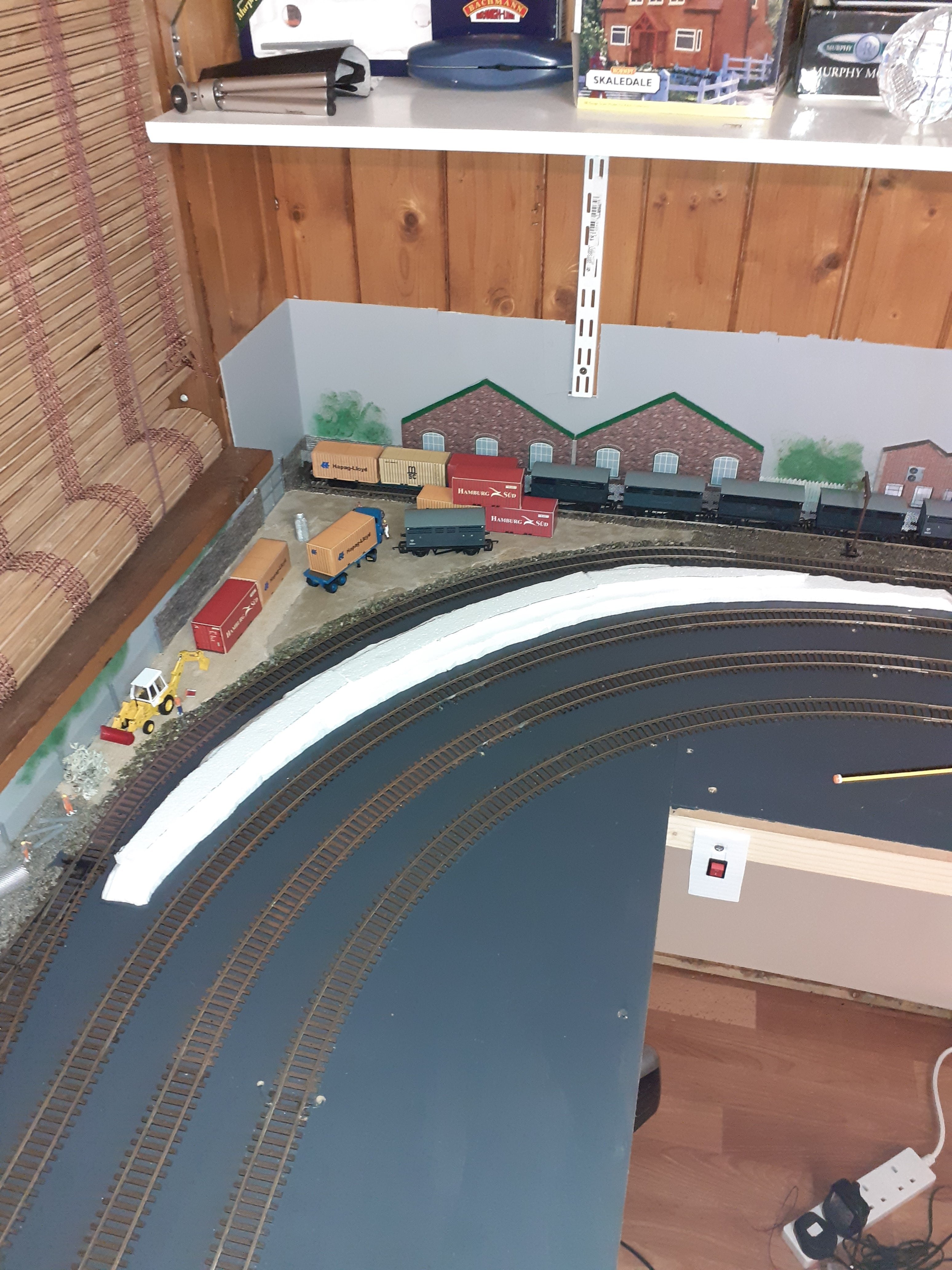
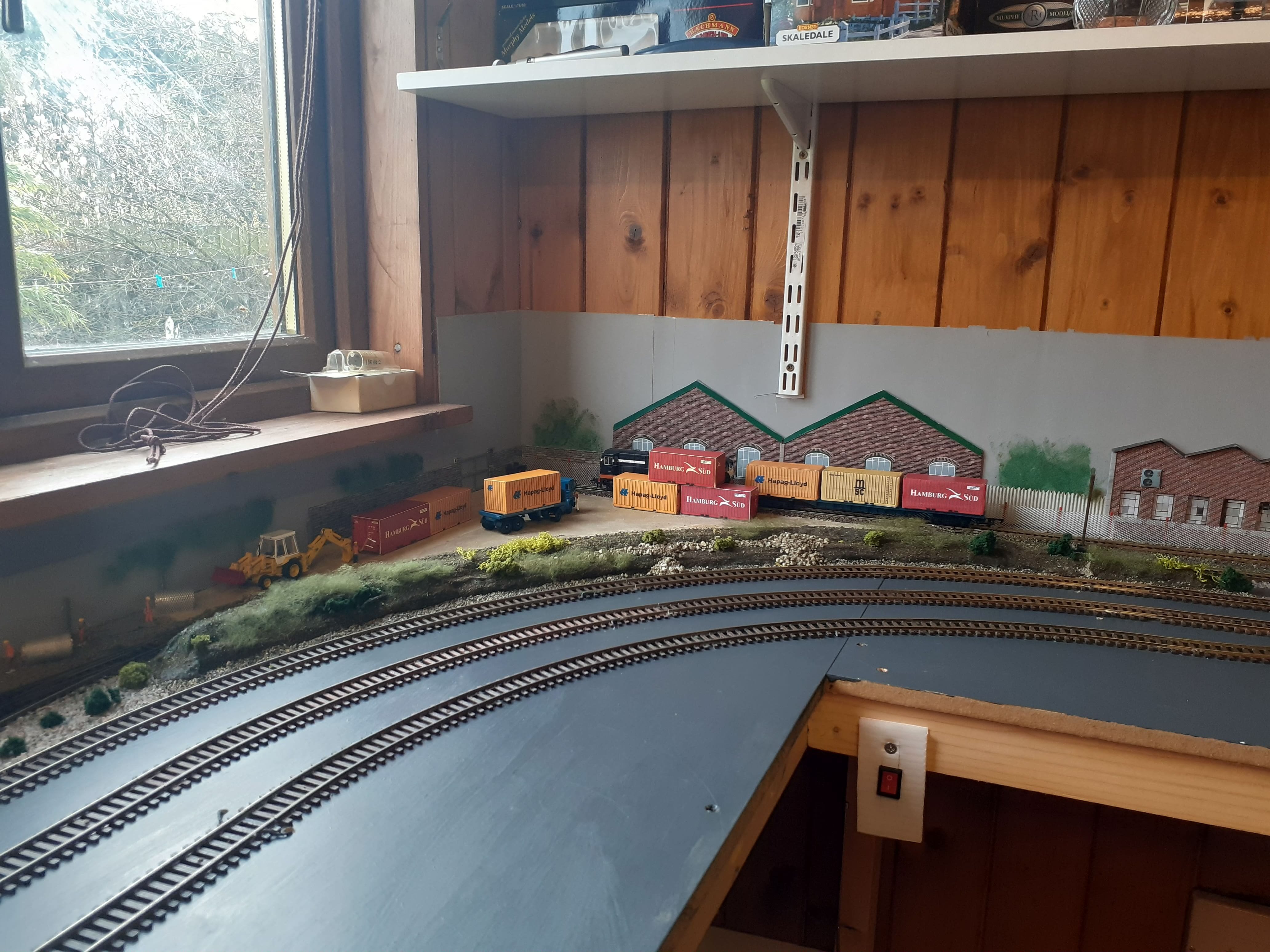
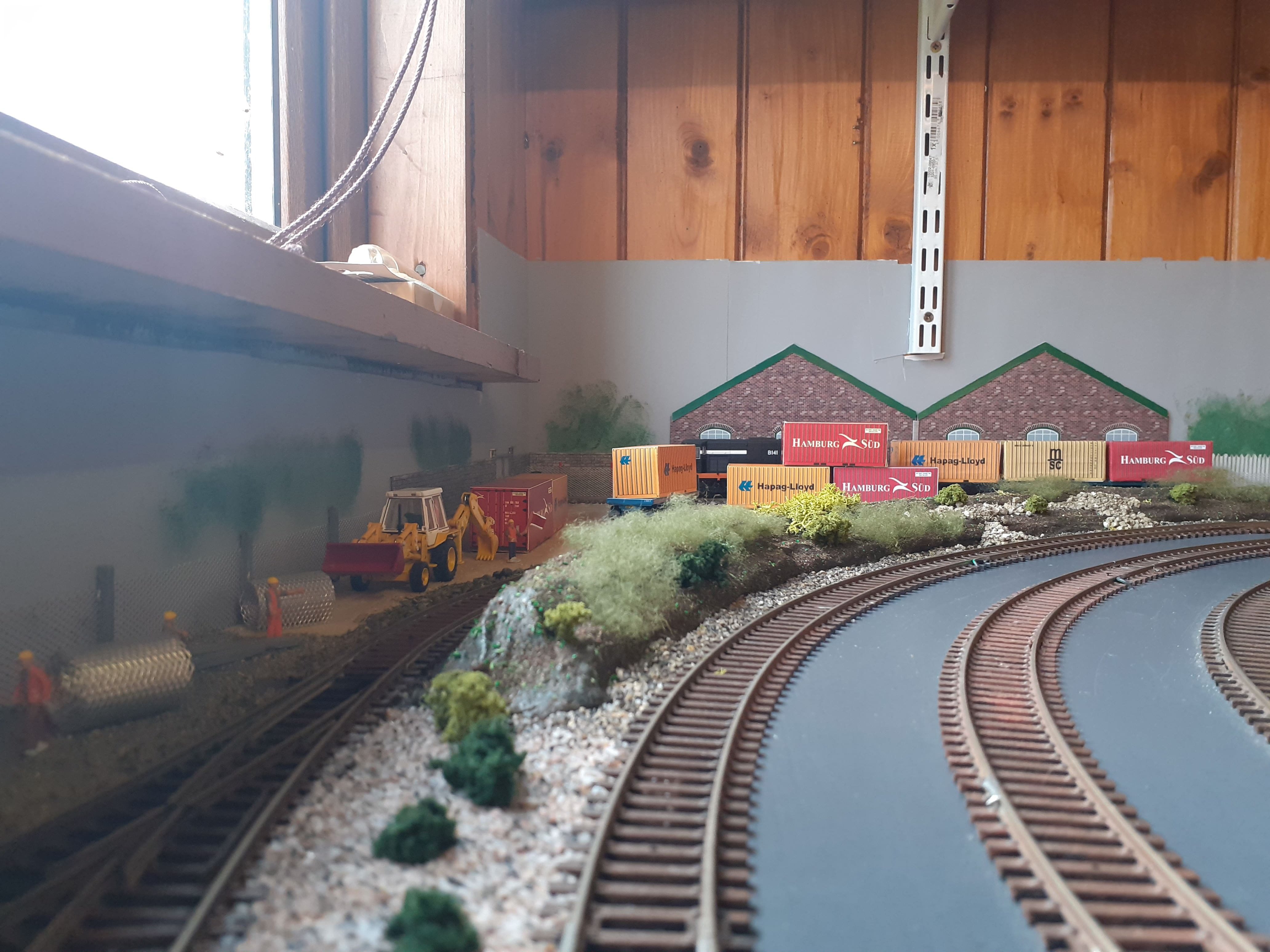
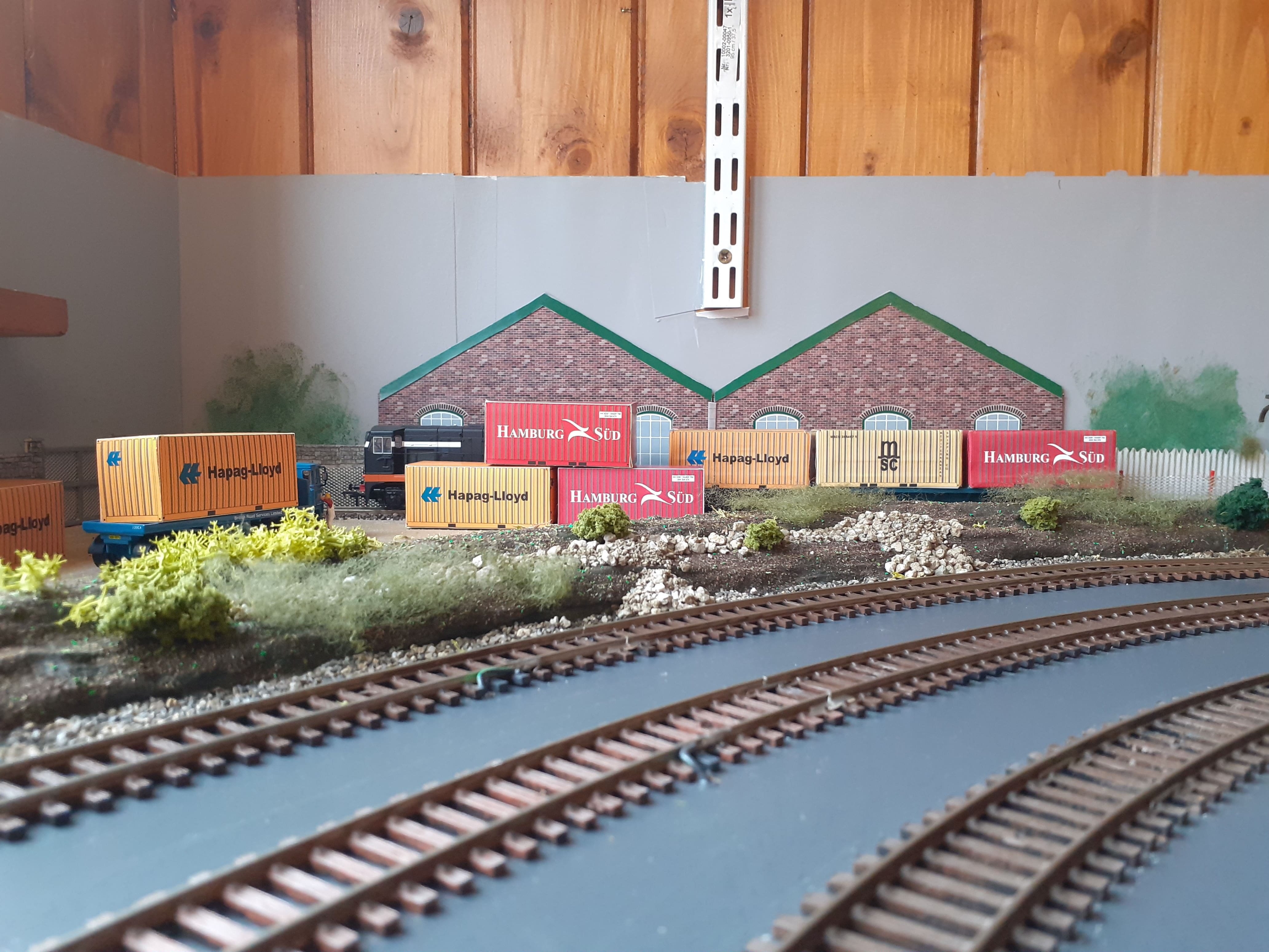
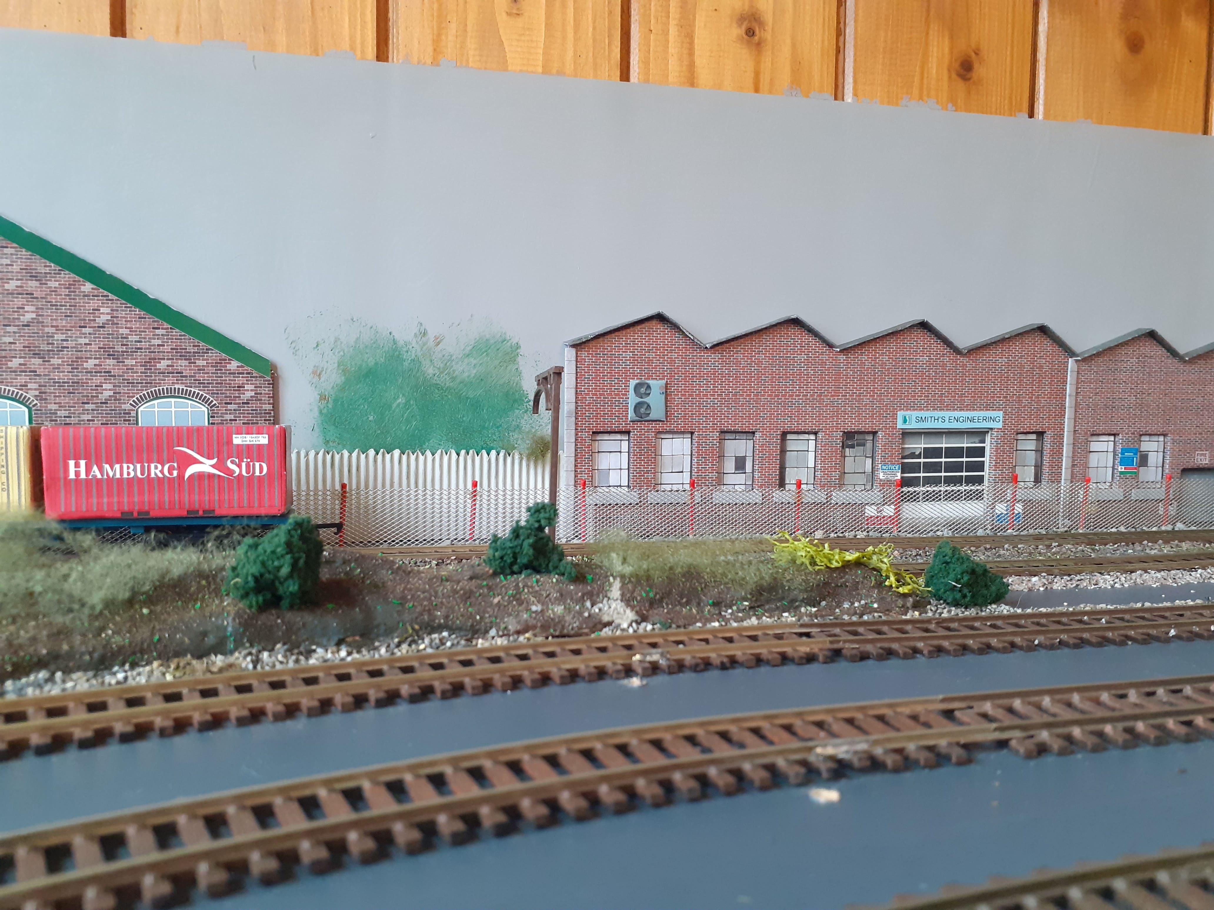
doing some scenic work
-
Diamond Crossing Protector
Paddy Mac Namara replied to Paddy Mac Namara's question in DCC, Electrics and Electronics
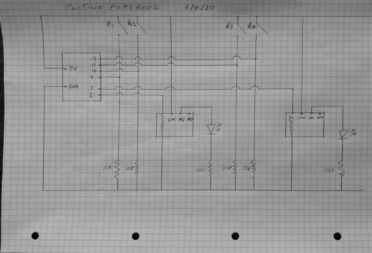
circuit diagram for above
-
Diamond Crossing Protector
Paddy Mac Namara replied to Paddy Mac Namara's question in DCC, Electrics and Electronics
This is how i would do two track control. But then I have three tracks.....so it's getting a bit messy. -
Diamond Crossing Protector
Paddy Mac Namara replied to Paddy Mac Namara's question in DCC, Electrics and Electronics
an improvement to the operation with reed switches my electronics workshop