KMCE Posted July 6, 2018 Posted July 6, 2018 Right........ Now that I have a properly printed model it's time to get started on construction. As mentioned in the earlier thread, I was proposing to use the high level kit as the chassis under the printed model, so made a start on the kit. The kit has parts for OO, EM & P4, so there are a few additional etches. Frames cut out of fret and bearings set in rear axle position – hornblocks for forward axle. I built the chassis up using the P4 components in the kit to arrive here: However........ Due to the 21mm gauge there was a lot of slack between the wheels and frames which was causing problems with how the loco sat on the track - the side play was excessive and to be honest the chassis was not the right shape anyway, so I decided to start again and build my own frames. More reflective of the actual loco, and allows me to correct the spacing to prevent excess sideways play. We get this: Great - right shape, compensation in, ride height set - now for rods. Ahh....wheel base in the kit is longer than 495! Thus coupling rods are no use, so I had to make my own. After using all the expletives I know (many times) and three goes later, we now have coupling rods - sort of! Not as elegant as the etched ones, but the difference in length can clearly be seen. Original RTR rods top, kit etched second, mine bottom. No lubricating pot, but I may be able to bodge something together. Now we are starting to get to a point where cylinders and connecting rods can be added, brakes fashioned, pick ups added and hopefully we will have a completed chassis. I hope to use parts of the kit to add detail to all of this, particularly in the cab area which will be very visible. More later..... 1 Quote
murrayec Posted July 6, 2018 Posted July 6, 2018 Hi KMCE 'expletives' a very handy modeller device- somehow by multiple use it all works out OK in the end! Looking Good Eoin 1 Quote
KMCE Posted July 7, 2018 Author Posted July 7, 2018 Progress for today. The new rods were binding slightly, so it was back onto the loco box to move the hornblocks properly in line. The axle posts allow the connecting rods set the correct distance and then its a matter of soldering in the horn blocks again. Relatively easily sorted, and now the chassis rolls properly without binding. Brakes were added from the kit and modified to suit the actual loco. Brakes are fixed to the 1.5mm crossing rod, which means they can swing out of the way to allow access to the wheels, while normally they can sit close to the wheel as per the prototype. Sliding rod supports from the kit were split and soldered into position using the cylinders as a guide. Next up was the gearbox which is formed from the kit etches folded up. All holes need to be gently opened with broaches to the correct sizes for shafts and bushes. Bushes were soldered in for the drive axle and assembly can commence. And this is where we hit a snag. When assembling the gearbox onto the drive shaft, it appears the gear on the drive axle (large one above with brass core) is a fraction to large to allow it mesh with the idler. No sequence of assembly allowed any space, so I think it will need a call to Chris in High Level Kits for advice. Gearbox connection to the drive axle - less the drive gear. This may need some lateral support as the space between the frames is much more than the kit envisaged, so without some fixing, the gearbox could slip. Perhaps the motor fixed in the boiler may prevent movement - I'll see how it goes. Continued on with other work such as motor into the boiler area, opening of the footplate to allow the gearbox through, and adding the cylinders. We are getting to a rather nice looking loco.... The wider frames move the cylinders out which gives a rather strong looking stance - shot from above showing how the cylinders sit in relation to the footplate. Very pleased with progress & its now starting to look more like the prototype. Ken 3 Quote
jhb171achill Posted July 7, 2018 Posted July 7, 2018 That's the little loco that shunted Allmans Distillery in West Cork, and was bought by the GSR, yes? Quote
KMCE Posted July 7, 2018 Author Posted July 7, 2018 Yes. The note on the drawing I have from IRRS states: "Purchased from Messrs Allman & Co. Ltd, Bandon for use on Anderson's and Victoria Quays" And while I have you, you being the Oracle on all things Livery, I have a note from the "Good Book" (Clements & Mc Mahon) that it maintained it's manufacturers paint scheme of Olive Green, lined in black & yellow with red frames. Whilst the photo is in B&W, there is no indication of colour variations or lining? Your thoughts? Ken Quote
murrayec Posted July 7, 2018 Posted July 7, 2018 Hi KMCE In the 'good book' photo, one can just make out the lining on the cab side around the numberplate, and on the sand/tool boxes- tool box top is black also? the links below give some idea as to how Packetts were lined which could help you - the last photo in the first link would seem a good starting point with the black lining and then add the yellow?? https://www.martynbane.co.uk/peckett/working/inservice.htm https://en.wikipedia.org/wiki/List_of_Peckett_and_Sons_railway_locomotives Eoin Quote
jhb171achill Posted July 8, 2018 Posted July 8, 2018 Ken That’s absolutely correct. The thing never had a repaint in its entire life! Along with the 800 class trio, it’s the solitary engine that the GSR didn’t paint grey! The exact shade of green is unknown, but if it were possible to research in England what the makers generally used, you’d be ok with that. The only thing the GSR did was to add a number plate, and since the engine was never repainted, it’s probable that the number plate was just unpainted metal too. Quote
jhb171achill Posted July 8, 2018 Posted July 8, 2018 Ken That’s absolutely correct. The thing never had a repaint in its entire life! Along with the 800 class trio, it’s the solitary engine that the GSR didn’t paint grey! The exact shade of green is unknown, but if it were possible to research in England what the makers generally used, you’d be ok with that. The only thing the GSR did was to add a number plate, and since the engine was never repainted, it’s probable that the number plate was just unpainted metal too. Those Peckett photos above would probably be correct, but in GSR days s heavy layer of weathering, almost obliterating the livery as in some photos above, would be more appropriate! Quote
KMCE Posted July 8, 2018 Author Posted July 8, 2018 Eoin, Many thanks for the links. There are a few images in there which will provide some indication of how she would have looked both new and old. Not having tried any lining, this should be quite a challenge..... JHB, Really appreciate the input, and I would agree that what ever the finish, a heavy level of weathering and toning down of the paintwork will be required. She will make a poor looking relative to the better looking locos to come. However, it should provide some very atmospheric photos with some heavily weathered and run down wagons. Will keep you posted on progress. Regards, Ken Quote
murrayec Posted July 8, 2018 Posted July 8, 2018 Hi Ken A fantastic aid to lining- by Wild Swan Publications - 'A Modeller's Handbook Of Painting And Lining' by Ian Rathbone, and Wild Swan's first publication of this type in full colour..... Truly a must have item in the toolbox ISBN 978 1 905184 54 5 Eoin Quote
KMCE Posted July 16, 2018 Author Posted July 16, 2018 Well.... Touched base with Chris in High Level and it turns out I have the wrong final drive gear - it should have 20 teeth, mine has 23, so new one on its way in the post. Good time to put this one to one side for a short while and start something new. Eoin, Many thanks for that link - I got the book. That chap takes painting seriously!!! It'll take some time before I get to that level, if ever, but fascinating information none the less. Regards, Ken Quote
KMCE Posted January 20, 2019 Author Posted January 20, 2019 After much hoo-hahing with other projects, the poor 495 was shelved for a while. It appeared in the background of some of the photos of other models, but was very much on the back burner. As I got the correct final drive gear from High Level quite some time ago, I decided to have another go at making some progress on this build. The hgh level kit is designed to insert the motor into the boiler and complete the gearbox while the cab was off, however given the 3D print was constructed with a full boiler tube back to the cab and a fixed cab, this was not going to work. Thinking cap on, I decided to redo the frames, include the fire box sides and create an underside for the boiler, which meant I could cut away the boiler on the 3D print, and include slots to allow the top of the gearbox up into the cab area. This means a separate running chassis and drop on body. Brakes on, cylinders, slides and cross head supports installed, gearbox completed and set in place to arrive at this. A front plate, which will both support the front of the boiler base, and tapered to replicate the back of the smoke box was added. Not overly visible due to the angle, but it will be seen later in one of the shots. As mentioned in other posts, the finish of the 3D print was not really good, which was only highlighted by a coat of primer. Much scrubbing with a fibre pen and some 1000 grit paper helped to reduce this roughness which will need another prime to check to see how the flattening is progressing. Plate replicating the back of smokebox is just visible in this photo. Some nicks and dings to be addressed, but overall the finish is better. In the interim, pick-ups were added at low level using a small strip of copper clad and 0.35mm PB wire, motor wired and running gear added. Quartering is proving to be problematic with slightly erratic running not helped by wheels not being completely true on the axles. In fairness the wheels are pretty trashed having being on and off too many times. I will get a set of spoked wheels from Alan Gibson which will more accurately represent the prototype which will help running. In spite of all that the loco runs; with an 80:1 gearbox this loco can operate at very slow speeds. I think a flywheel may help to smooth out the running also. 20190120_190334.mp4 More soon, Ken 1 1 Quote
murrayec Posted January 20, 2019 Posted January 20, 2019 Looks great Ken I actually bought an rtr one of these in Marks recently, unfortunately it's black but that will be sorted- sometime? Eoin 1 Quote
David Holman Posted January 22, 2019 Posted January 22, 2019 A fine piece of work, Ken. Highlights too the issues with 3D printing. At a meeting last night, was looking at a 7mm scale open wagon, done complete. From three feet away, it looked impressive, but any closer and the layered effect soon became apparent. Likewise a printed coach, where not sure any amount of sanding and polishing would give a smooth surface and retain the panelling. Apparently, the wagon took six hours to print and many days to get the CAD right. Fine if you enjoy that sort of thing, but not for me just yet, not least because I can produce masters for resin castings in a few hours and once the moulds are set, churn out sides and ends every half hour or so. While I'm here, total respect for the outside cylinder work. I've done St Mologa in 7mm scale, using the Tyrconnel kit. Small engines and outside cylinders make for fag paper clearances around the cross heads. Add in broad gauge and it gets tighter still. Like you, had to move the cylinders out slightly, plus bore the piston rod holes slightly off centre to make it fit. Pretty engine though, so worth the effort. 1 Quote
KMCE Posted January 23, 2019 Author Posted January 23, 2019 (edited) Fiddly little bugger! Parts from the High Level Pug kit - nice cast brass parts. Needs some tidying up and painting! Ken Edited January 23, 2019 by KMCE 4 Quote
KMCE Posted March 18, 2019 Author Posted March 18, 2019 Some progress on 495. Chassis insert into the body is sorted which allows fixing of the cab interior in place. This then allowed addition of handrails, cab back and roof. Buffers, hooks, and sandbox operating rods were also added. I will need to add some weight as it is a little low on tractive effort. When pulling the 5 wagon rake, which in fairness is quite heavy, it does struggle on occasion. Some weight between the frames, front and rear should help. It does run well and looks well hauling the rake of wagons. Some more detailing needed before heading to the paintshop as it is looking rather scruffy at this stage. Quick shot of 495 on the siding with 423 on the main track. More as time permits. Ken 2 1 Quote
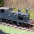
KMCE Posted June 18, 2019 Author Posted June 18, 2019 495 is finally at a stage where painting can begin. 495 was one of the few locos in Ireland that did not get the overall coat of grey, and remained in its original makers colours of olive green lined in yellow & black. Painting the body at the moment - will get to the chassis later. Lining is proving to be interesting - I'm using a Rotring draughting pen with yellow ink with technical drawing templates to help get squares & curves. Keeping it simple for the moment & building up slowly. The intention will be to weather this very heavily as the original never got a coat of paint so fine detail will not be critical. Getting there! Ken 7 Quote
jhb171achill Posted June 19, 2019 Posted June 19, 2019 A fascinating little loco with a unique history. Being one of the comparatively few “private owner” locos in Ireland, and a one-off at that, makes it of particular interest. Something like its original home, a distillery siding, or its latter home shunting dock lines in Cork, or indeed a fictitious “one-off” like it would make an interesting shunting layout concept for those short of time of space. Long run I’m thinking of a 21mm gauge small shunting outfit like that with maybe a G and a few wagons... That loco will look great when it’s covered with weathered gunge! 1 Quote
Recommended Posts
Join the conversation
You can post now and register later. If you have an account, sign in now to post with your account.