

David Holman
-
Posts
3,702 -
Joined
-
Last visited
-
Days Won
98
Content Type
Profiles
Forums
Resource Library
Events
Gallery
Blogs
Store
Community Map
Posts posted by David Holman
-
-
Do like an overall roof.
-
 2
2
-
-
I may have posted something similar before, but the choices made by manufacturers in the past have sometimes been odd, like the Hornby Dublo/Wrenn R1 0-6-0Ts, which only really got used on the Folkestone Harbour branch. This was very much back in the day, whereas we now have sensible options like Stanier Black 5, Terriers, etc, etc.
I suspect that in the past, choices were driven by what could be easily produced, whereas now, options are more varied. However, from an Irish, steam outline point of view, a key choice will be whether a new rtr loco can be converted to 21mm gauge or not. New diesels seem to be made that way, but for any steam loco with splashers, outside cylinders or valve gear, suspect it becomes a production nightmare. Add in the fact that there are very few steam locos that avoid ticking these boxes and suspect whatever is produced will perforce be limited to 16.5mm gauge, though guess that is unlikely to worry the majority of potential buyers.The
By the by, does anyone know if the 7mm scale Ruston 88DS is easily converted to 36.75mm gauge? Likewise the little Hunslet 0-6-0T which bears more that a passing resemblance to one used on the Fenit branch and elsewhere the the South West?
-
 1
1
-
-
A further thought is that where I suggested a ground signal on the crossover leading from platform 3 to the up main line, this isn't needed. On the real railway, this move would be protected by interlocking the signals and points - the signal could only be pulled off/clear, once the points were set for this move.
Signal enthusiasts in the model world will take great delight in replicating such things (and why not, if that is your thing), though as in the real world, such things are complicated.
-
Oops! You are correct. Have indeed swapped 1 & 3. Well spotted.
-
He should be paying someone to take it away!
-
 2
2
-
-
Good old imperial measuring! How many cubits is that?

-
1
-
-
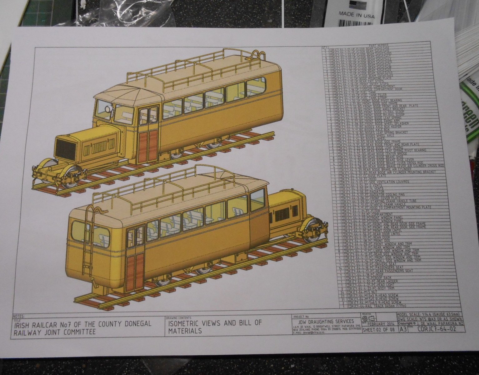
Thanks Alan. Somewhere in RMWeb there is a thread of one being built like this. Look up the images for Donegal railcars on Google and eventually you come to a picture and just visit to get to the thread. That's how I found the 1:14 plans from New Zealand as well. Only problem with such searches it (if working in more obscure fields), you think you found something useful, only to discover it is one of your own posts, often from this very forum!
-
2
-
-

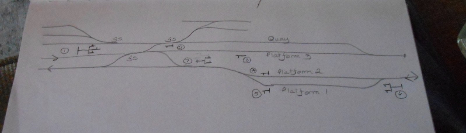
Above is just one take on how you station might be signalled, but no doubt there are other options:
- Signal 1 is a three doll unit. The left arm signals a train from the main line to the quay. The middle arm controls entry to platform 1, while the right hand one is for platform 2 or 3. The left doll would probably be shorter than the other two.
- Signal 2 is a starter, with a single arm and will sit at the entry to the quay siding, for a train leaving this
- Signal 3 is also a starter and will sit at the end of platform 1
- Signals 4 and 5 are also starters for platforms 2 and 3, should they been used for both directions, otherwise signal 4 is not needed.
- Similarly, signal 6 has two dolls on its post, although if only up trains use platform 1, then just a single signal is needed. However, there will then need to be a starter signal at the other end of platform 2, for down trains to start. There will need to be a starter at this end of platform 1 as well, if both lines lines are bi-directional
- Three possible sets of ground signals might be included, as marked GS on my sketch. These would cover entry to/from the sidings, though only the middle one is essential, as it is on the main running lines and would guide a train from platform three on to the up main line. The other two ground signals, to the quay and other sidings probably aren't needed as these points would like as not be controlled by hand levers adjacent to the track.
Hope this helps - other options are possible, while you then need to decide what sort of signals you want and there is plenty of choice for that!
-
2
-
1
-
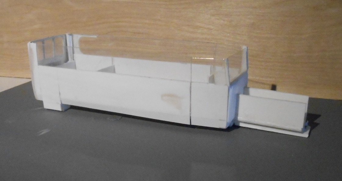
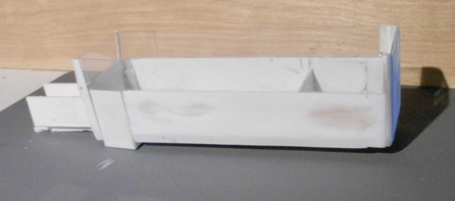
Managed to fit in a bit of work on the railcar this week & and giving it to Mark before I go any further, so he can look at creating a chassis.
Nothing to fancy in the construction. The sides are being built around 1mm clear acrylic sheet, overlaid both inside and out with 20thou plasticard. A fair bit of car body filler will be needed to create some of the curves and to deal with where my over enthusiastic use of MEK solvent has caused blemishes.
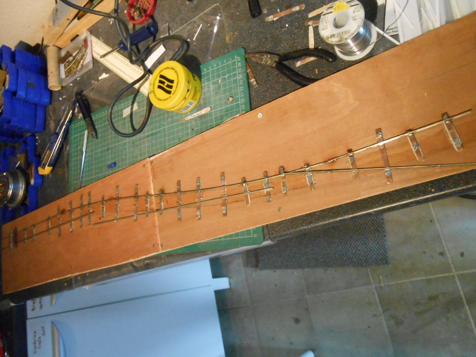
One additional thing I'm doing for Mark is building a short piece of 21mm gauge test track. This is just a piece of plywood with two three foot radius reverse curves. If the railcar can negotiate these, it should be fine on my layout. Needless to say, this item is not finished yet!
-
11
-
-
Have you realised you are still not a year into this project yet? Amazing progress.
-
1
-
 1
1
-
 1
1
-
-
So, double track main line coming in from the left. Single track line entering from the right. Will platforms one and two be just up and down separate, or will you want them both signalled for each direction?
Potential for a multiple doll gantry across the three tracks where you have written "long sidings", with arms controlling entry to the quay and platforms 1-3 in one direction, plus starters from the quay and all the platforms in the other. That's before adding shunt signals to the long sidings. Could be positively bristling, but a serious job to build, let alone make work.
Something simpler with several, separate posts probably better.
Another question - will they be hand operated, remotely controlled or just decorative? Either way looks an interesting project.
-
2
-
-
Thanks folks and love the LTSR dodge, Andy!
Saw that pencilled in date on the underside - also that the model appears to be three rail, which I hadn't considered, but makes sense I suppose.
-
Thanks folks - useful to see how the pony truck connects to the front end, plus the lumps of lead there too. Square section fuel tank on the left, I see.
There are anomalies in both the 0n16.5 drawings and the large scale set. The former has a much steeper ridge to the bonnet too (clearly not the case in photos), while the latter has the windscreen with a V profile.
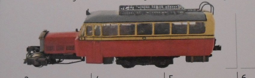
Fry's model looks like 'original' condition, with the big front overhang of the roof and no front coupler, or the sheeted/plated between body and bonnet front. What a stunning model though, especially for its day.
-
1
-
1
-
-
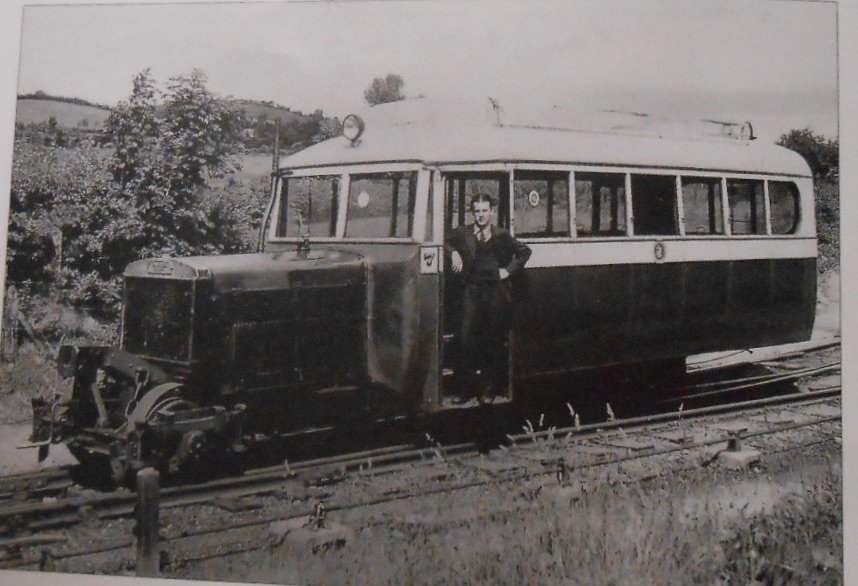
Followers of my Workshop thread will have seen I'm starting to build one of these railcars in 7mm scale.
I've got some drawings and several photos, both in books and last year's Donegal Society calendar - as per the fine model above. One or two questions have arisen since I started making the basic shell of the model and any help with these will be most welcome:
- The area around the engine/bonnet always seems very dark in photos, so any info on both the front end and the lower edge of the bonnet will be useful
- Likewise the front pony truck and front coupling
- What colour were the seats?
- The fuel tank, which I think should be on the right hand side: is it round or square?
- The top picture shows an interesting cowl/cover linking the front of the body with the bonnet. Guess I'm probably going to represent this with filler, filed to shape, but what was it on the prototype? Tarpaulin, beaten metal, or something else?
- Precision Paints do the correct Donegal colours, but does anyone know of a good match car rattle can by any chance?
- What colours should I paint the driver?
- Are there any commercial transfers available for the Donegal in 7mm scale?
Many thanks.
-
2
-
Can't delete! The other thread is the one I want
-
1
-
-
Suggest you provide a sketch plan of the layout. Need to know which are the running lines and which are just sidings. Is the station a terminus, or part of a continuous run?
From this it should be possible to work out what signals are needed and where.
-
2
-
-
6mm birch ply by the look of it?
Nice. Very nice!
-
We wish!
-
1
-
-
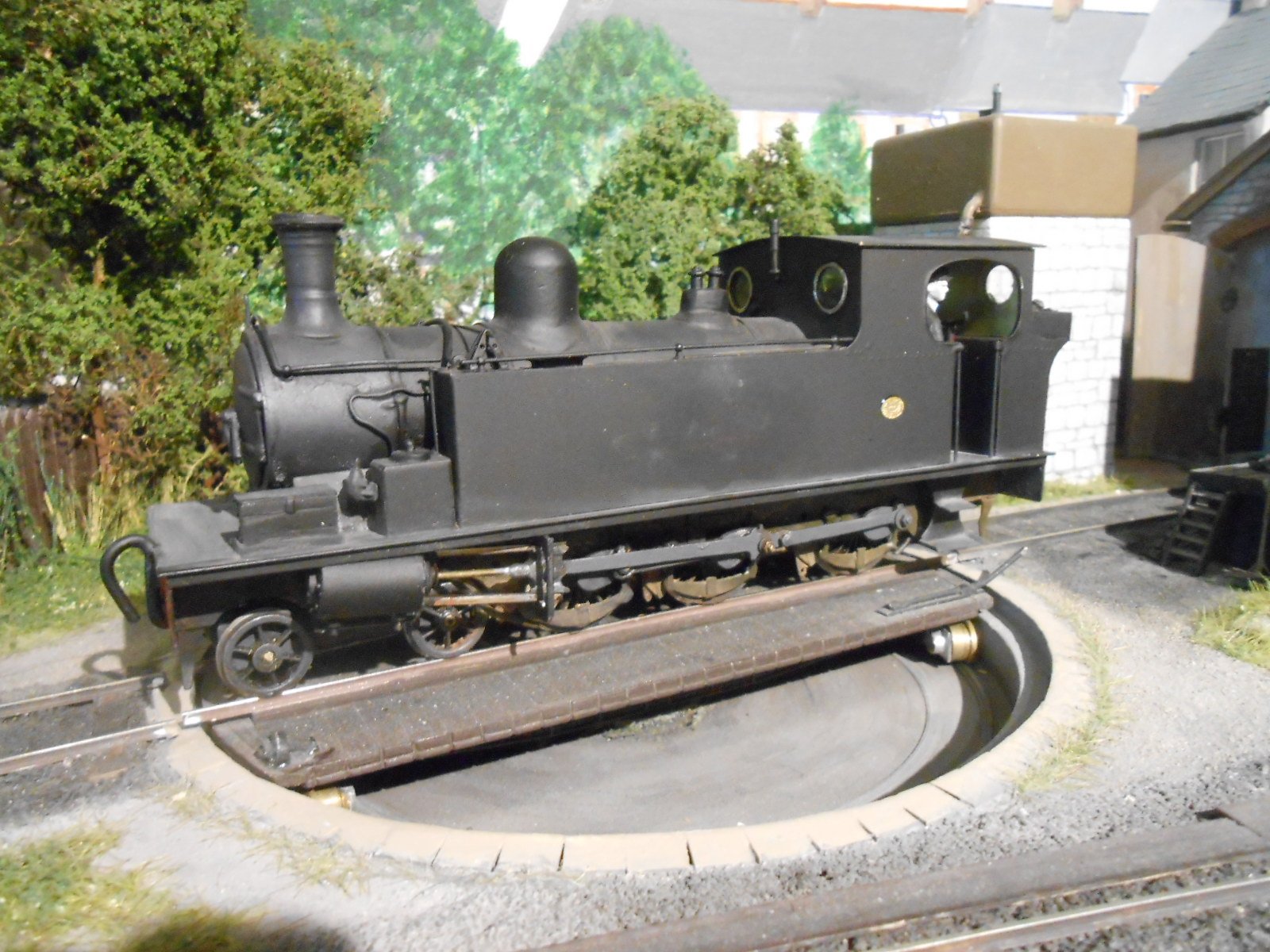
The builders plates finally arrived for the Barclay tank, so have now been glued in place. Slightly disappointed with them as they are not legible, but they only cost me a fiver, whereas the set I commissioned for Wolf Dog came to over forty quid. You pays your money...
So. while there are unfinished projects with both Swilly and Donegal wagons, decided it was time to start looking into a brand new project, namely Donegal Railcar number 7. Part of my Swilly-Donegal makeover for Fintonagh involves repainting Clogher Valley Railcar No 1 and likewise making Phoenix out over the Atkinson-Walker tractor. However, I want at least one more railcar and it will need to be one of the earlier models as none of the later, four coupled ones will fit on my turntable. So, number 7 it is, or indeed number 8.
They were historic vehicles, being the first ever diesel railcars, certainly in these islands and maybe anywhere. They could haul up to four wagons and often worked in tandem with other railcars. Photos are available & I have a couple of decent drawings, plus there is a useful section in Roger Cromblehome's County Donegal Companion. So should be straightforward then? Well, not exactly it seems.
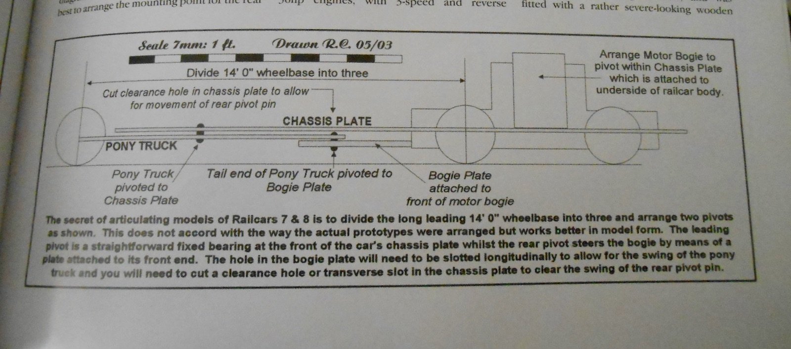
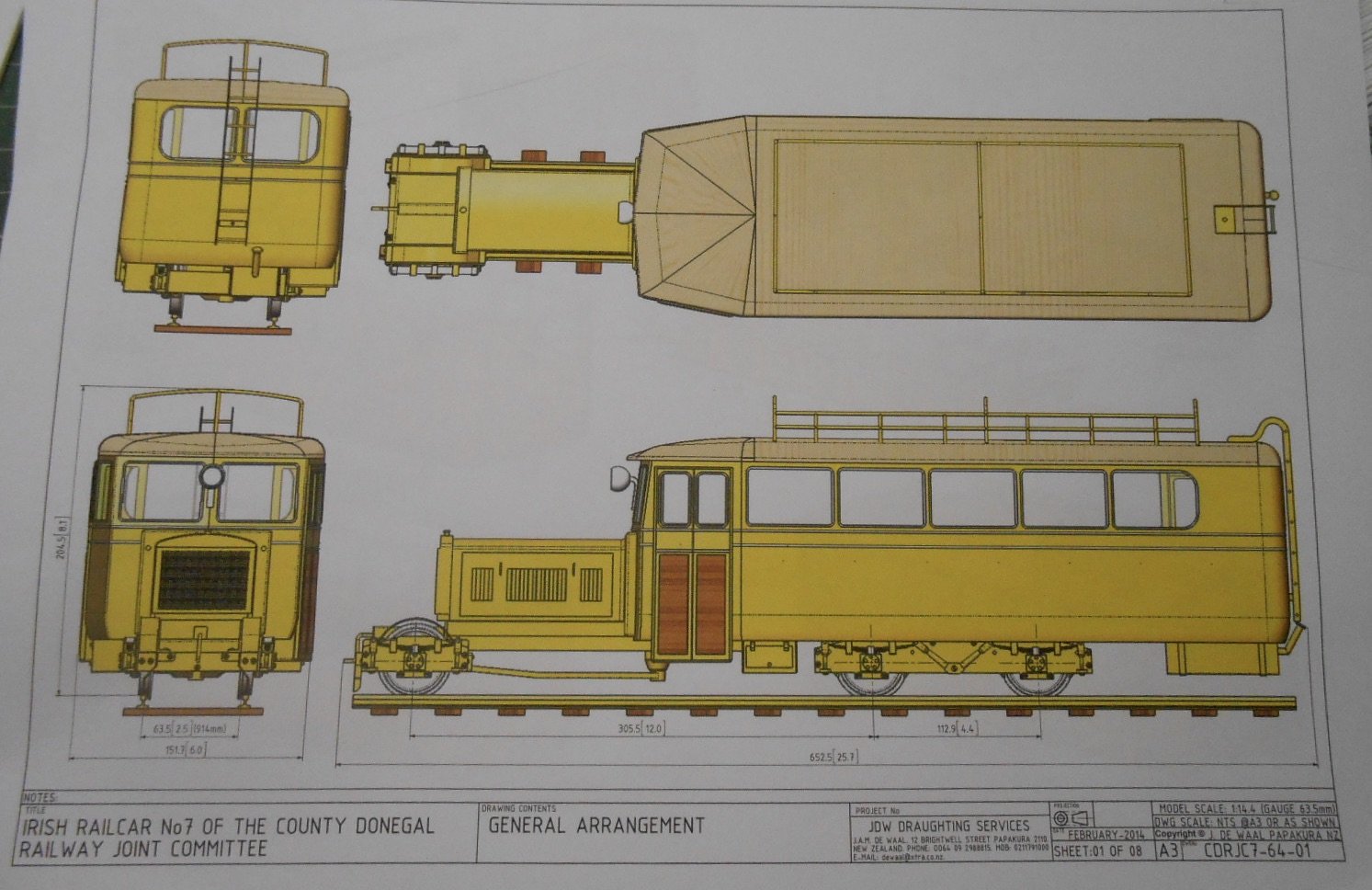
The main issue is the chassis, with a scale 14 feet between the rear bogie and the front pony truck. The latter is pivoted just under the driving position on the prototype, but Roger suggests this will not work well on tight curves in model form. The bogie itself is 5'6" wheelbase, which if trying to adapt a 4mm scale one means 38.5mm and so far, have not been able to find anything suitable.
However Mark Clark's 'Locos & Stuff' website offers a host of 3D printed options and with Mark being a Chatham Club member, this seems the way to go. Mark is also one of life's genuinely clever people who has taught himself 3D printing, in the process learning how these machines actually work. He also understands way more about mechanical things than me & agrees with Roger's description on making the railcar's chassis.
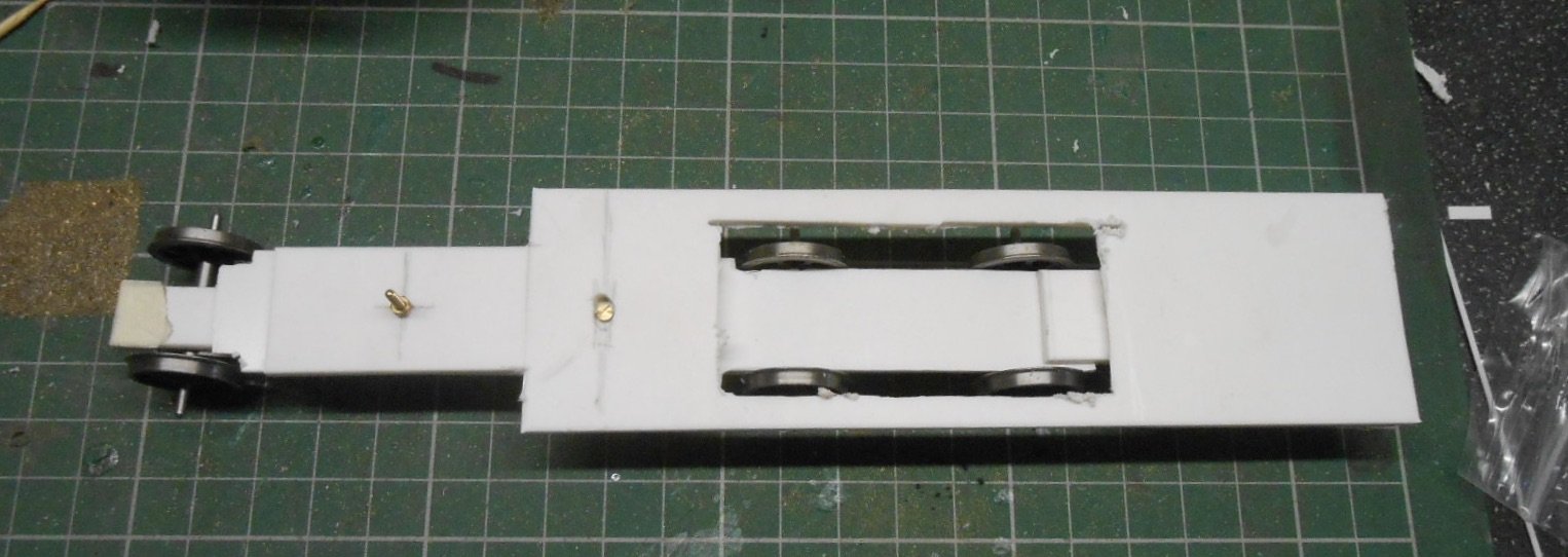
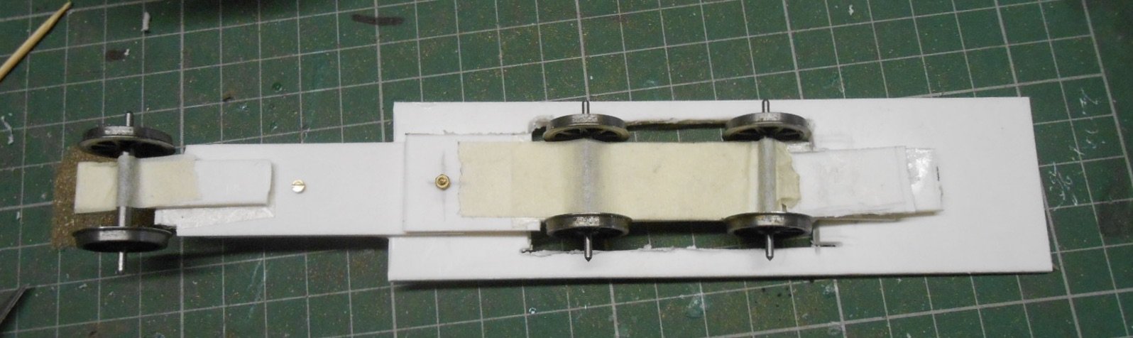
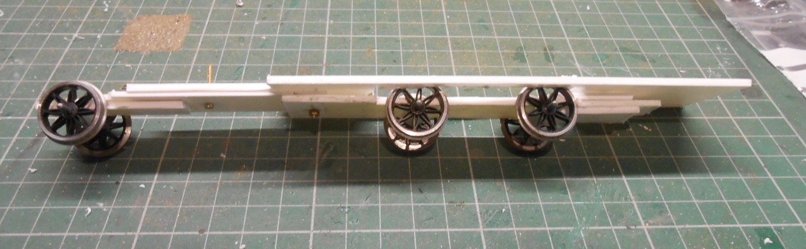
The photo above shows the basic principles, while those below show my lash up, in plasticard, which I did this morning in an effort to understand how it works myself.
The wheels are just held in place with tape [they are too big anyway], but despite my doubts, the idea does indeed seem to work. What fuddled my brain most was the single fixing point to the chassis plate [at the front pivot]. The front pony truck swings on this while the motor bogie will pivot from a second point further back. What wasn't clear [to me anyway] in Roger's drawing is that the main chassis plate [which is fixed to the bodywork] rests on the rear of the motor bogie giving all important weight to this and therefore aiding traction. Anyway, am leaving this to Mark as [like one or two folk on this forum] actually finds this stuff fun!
So, watch this space.
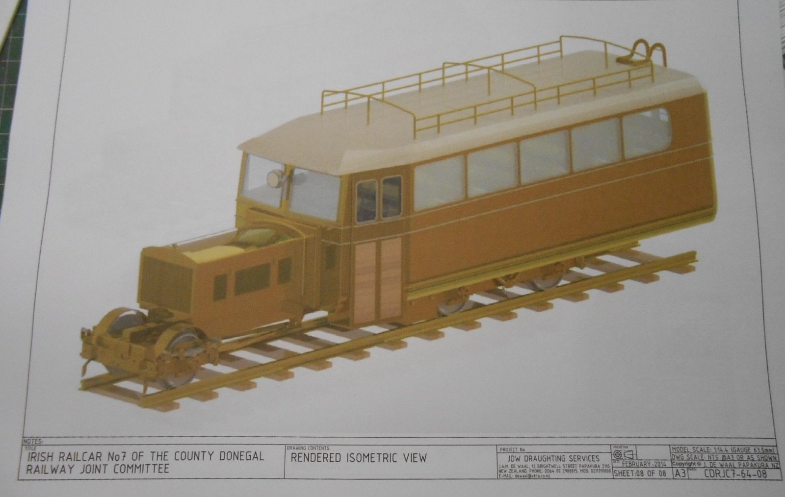
Am sure it will not be a quick build and in any case will need to fit round other stuff. However, discovered something that Mayner is no doubt familiar with the other day, in the form of a fine set of large scale drawings for a 1:14.4 [64mm gauge] drawings of the railcars. Scroll down far enough in a Google search and you'll eventually come across them. They appear to be made for what looks like a laser cut wooden kit, but certainly offer a lot of interesting detail.
-
10
-
 2
2
-
-
Nobody should think 21mm gauge requires P4 standards. 00/EM finescale (ie existing wheels) should be fine. However, do not expect to use sharp radius curves or points - they will need to be at least 3 foot radius, unless you are using short wheelbase stock and even then two feet will be pushing it.
Also, while modern diesels seem easy enough to convert, steam outline models are not.
-
4
-
-
No great links to the Irish scene, but they are closing after 50 years of making some very fine kits. Fortunstely, Squires are taking over.
Meanwhile the Warley Club are going to run a new exhibition next year at Statfold Barn with its rather splendid collection of narrow gauge locos.
The above from the latest edition of Railway Modeller.
-
3
-
-
May be wrong, but my impression was you can't do much with these Mamod engines other than run them round a circle of track, so once the initial novelty wears off, suspect most will have sat on shelves/gone back in their boxes. Apart from the general lack of controlability, as already outlined, they work via the cylinders rocking up and down like a see saw, as per other Mamod products, so not exactly prototypical either.
That said, as a project for a tinkerer, there is scope to get them running nicely, but not for the faint hearted.
-
2
-
-
Looks another fine model. Who is going to be first in giving them some serious weathering? Looking forward to seeing the results.
-
1
-
1
-
-
Great news Paul - and about time! If I had mine again (and knowing what I know now), S would be very tempting. Lovely scale, lovely size and that rather enigmatic, imperial track gauge too. Sixty three sixty fourths of an inch for those who didn't know.
Looking forward to reports as the project develops and what a jewel Elf is too.
-
1
-


BROOMBRIDGE JUNCTION
in Irish Model Layouts
Posted
Quite a prospect. Sweeping curves, varying levels - so much to like!