

David Holman
-
Posts
4,163 -
Joined
-
Last visited
-
Days Won
114
Content Type
Profiles
Forums
Resource Library
Events
Gallery
Blogs
Store
Community Map
Posts posted by David Holman
-
-
1
New school scratchbuilding? Certainly very impressive. A model like this would be an absolute pig to build from sheet metal alone and while a 3D print might work, this is a more elegant solution, keeping all the fine edges, open louvres and so on.
I wonder how the CAD/etch/assembly route compares to making everything by hand? Both are genuine skills that need to be learned and practiced, as well as the ability to visualise how to turn a 2D drawing into a 3D structure.
Either way, technology opens up more options and if I was starting again, learning CAD would be right up there with metal work and electrics.
-
 2
2
-
 2
2
-
-
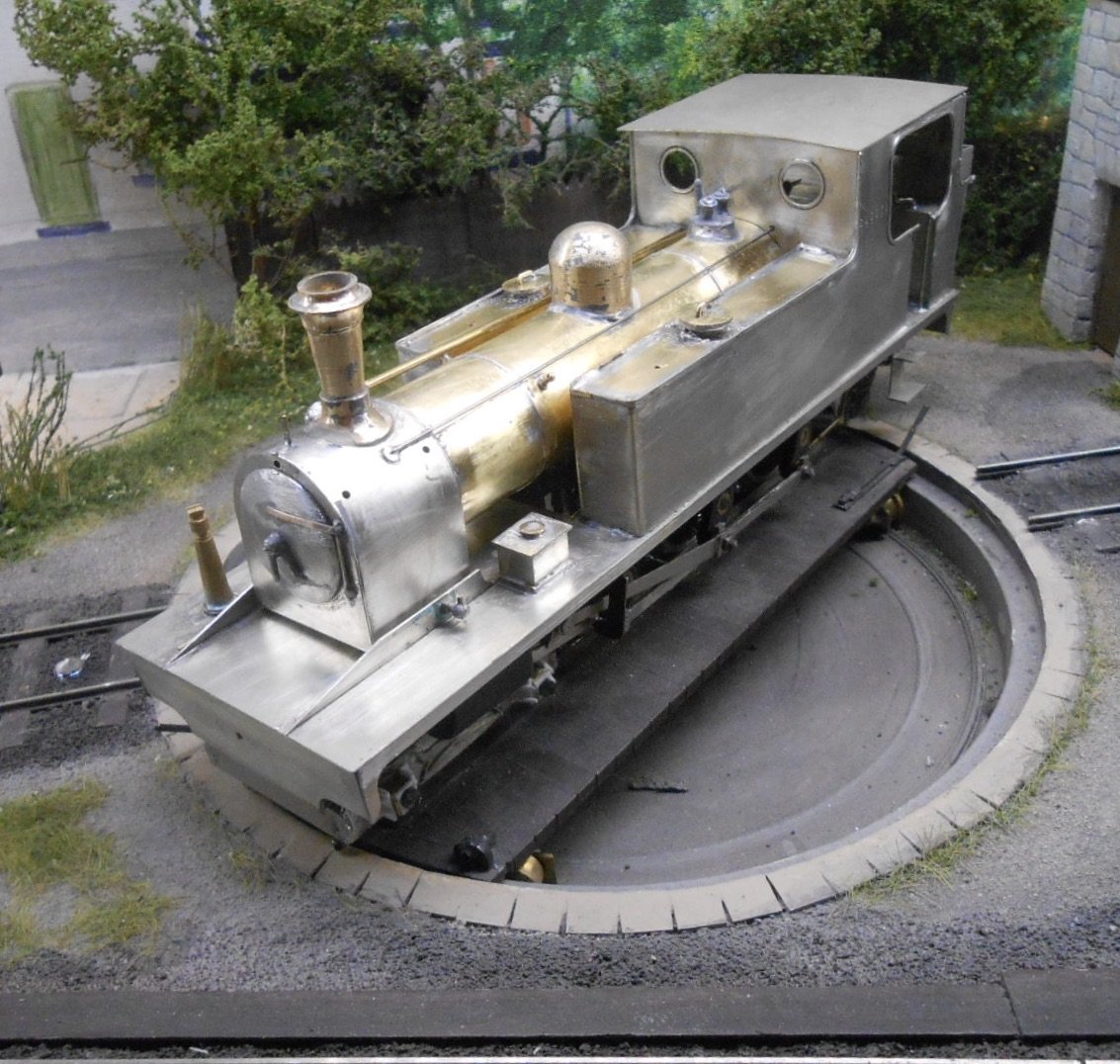
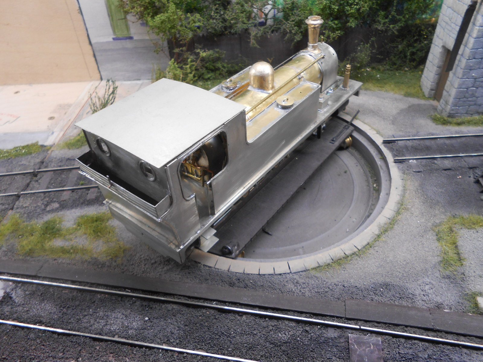
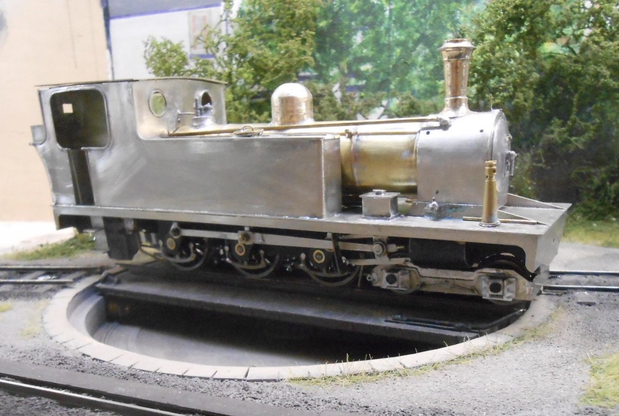
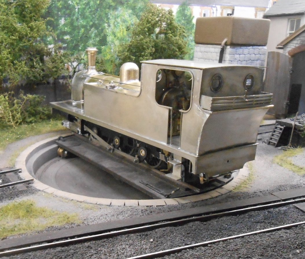
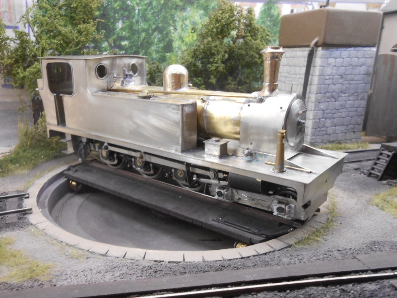
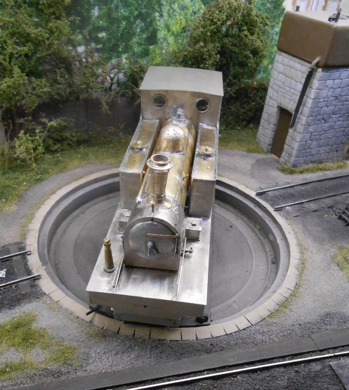
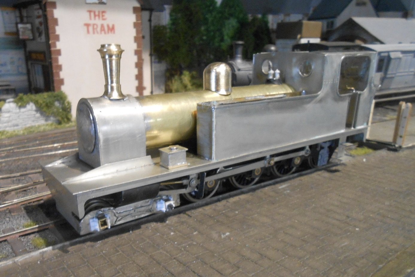
Been adding all the details this week - quite a lot, though the Kerr Stuart is fairly simple in outline. Various components included:
Chimney, dome, safety valves and whistle

Various footplate fittings, such as sand & tool boxes, jack and vacuum pipes, plus the tank filler caps
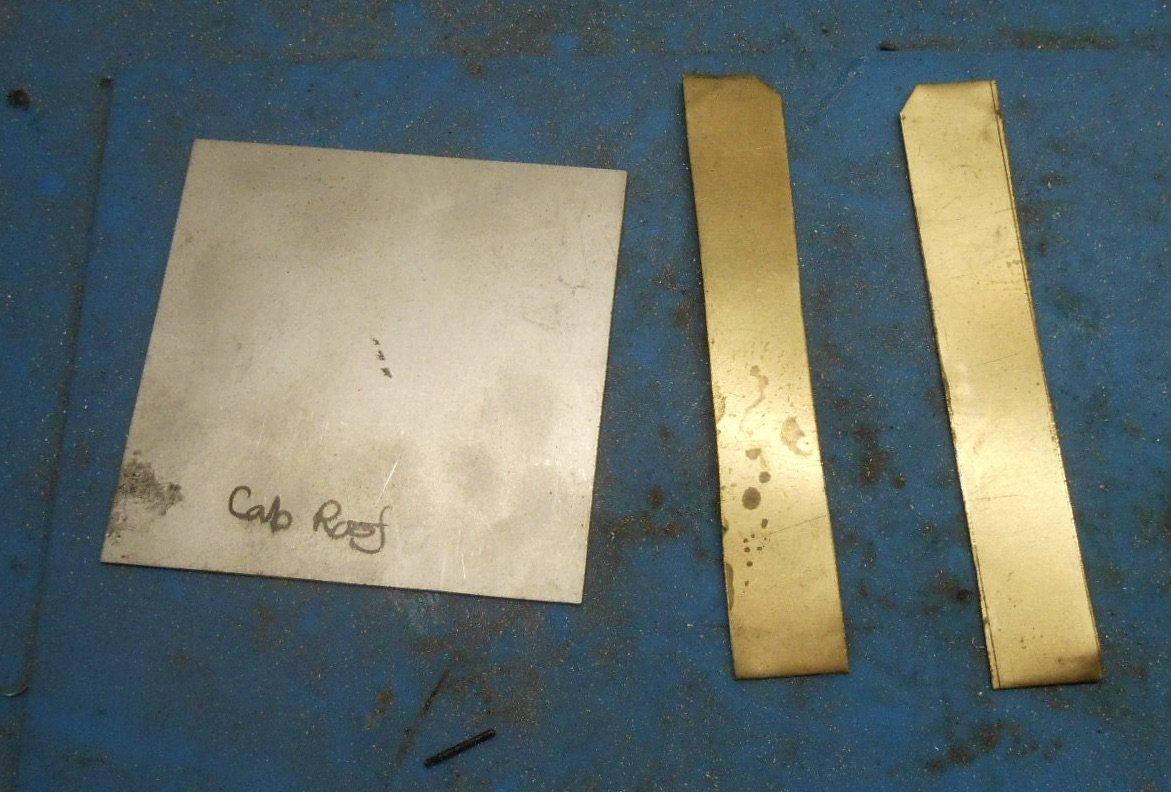
Tank tops [after filling the tanks with lead sheet] and cab roof.
Then on the chassis, brake rigging and springs. The 5 thou phosphor bronze strip above the spring hangers was used to make the boiler bands.
Once added, it was then a case of a thorough clean/sand/file/scrape to remove excess solder, flux etc. The model is therefore now ready for the paint shop, so the pictures below are the last ones of it in its bare metal state.
Still awaiting some short handrail knobs & builders plates. While most fittings are fixed in place, the cab roof, firebox and boiler are still loose to aid the painting process. However, some basic running has taken place & [fingers crossed] the model seems to run nice and smoothly.
-
9
-
 5
5
-
-
No doubt one will be cheaper than the other and available sooner?
-
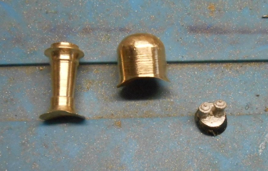
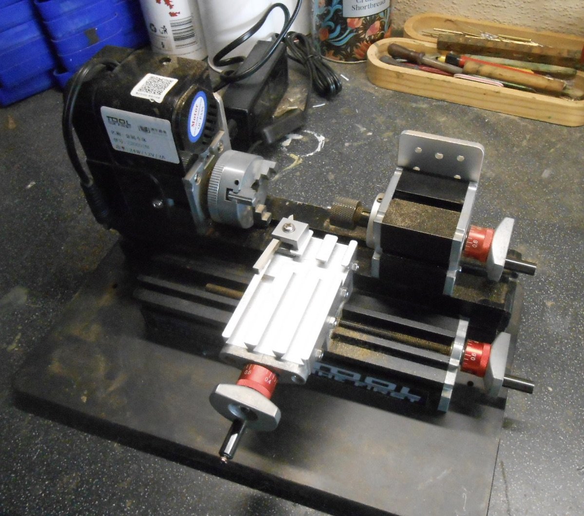
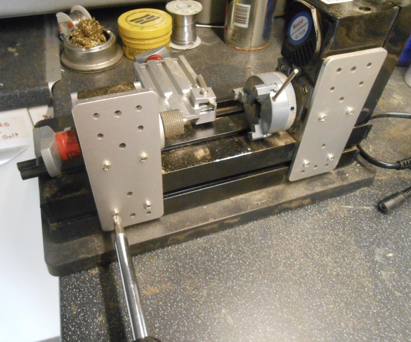
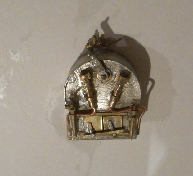
With no instructions to follow, the next things on the 'to do' list tend go go on a bit of a whim and therefore decided yesterday afternoon, it was time to get the lathe out and have a go at the main boiler fittings.
I use the word lathe advisedly. Mine is about as small [and cheap] as they come, but have so far managed to produce three sets of chimneys & domes, plus several buffers; however high tech it ain't, while I am very much self taught.
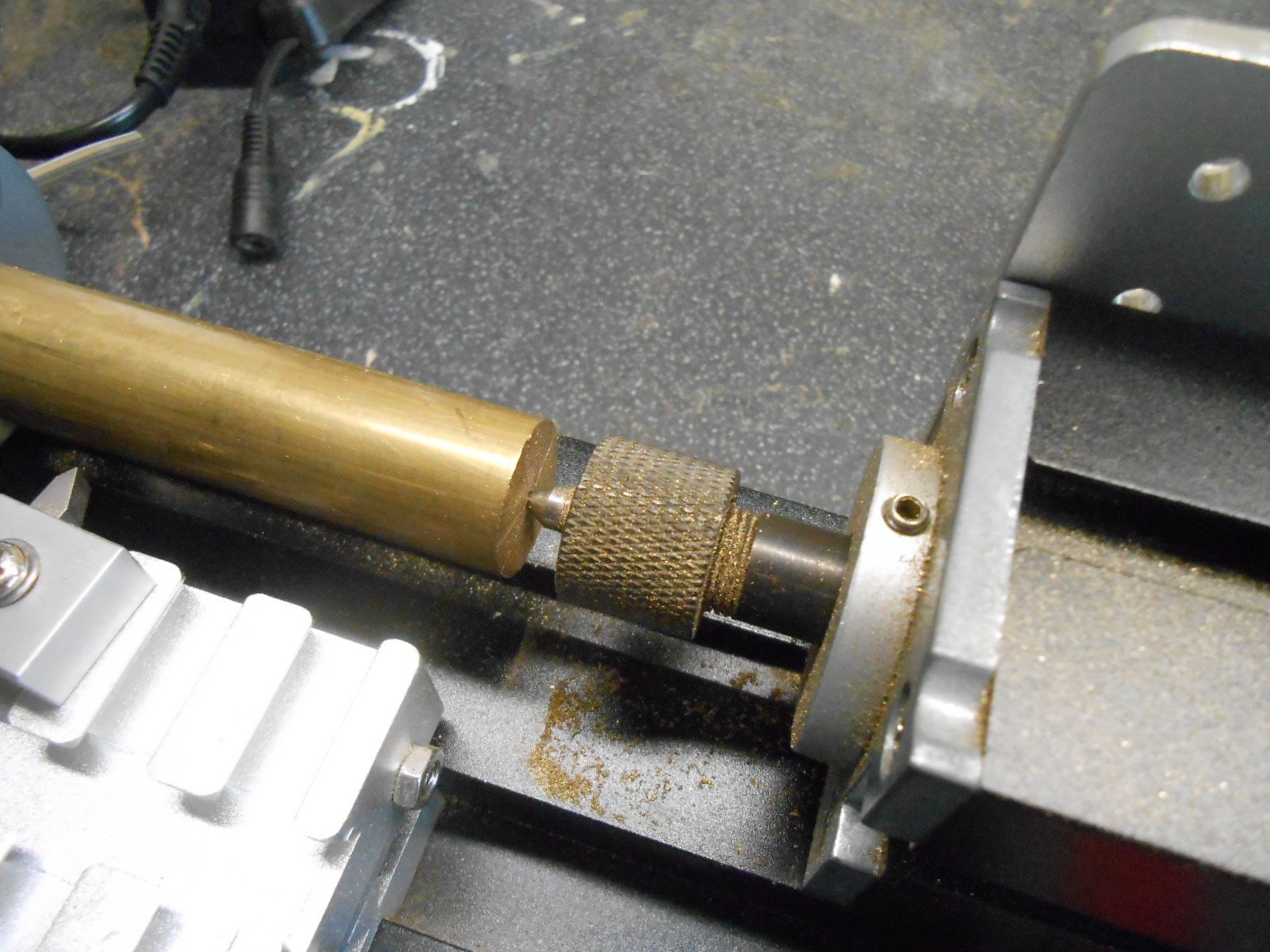
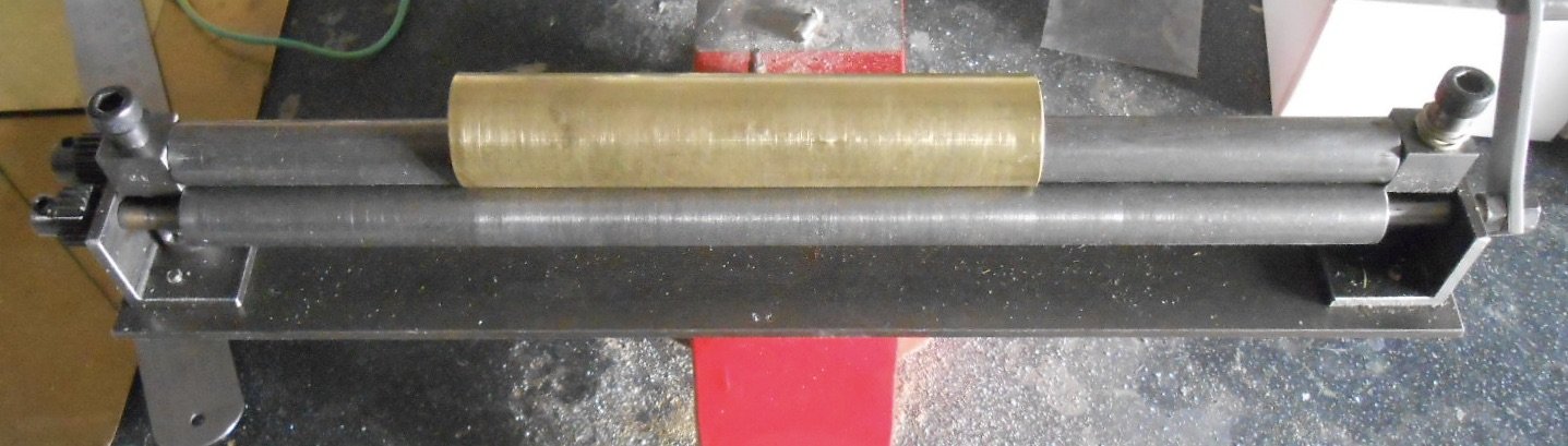
A useful tool that came with the lathe is this plastic gizmo, which is helpful in find the centre of the brass rod, then a hole is drilled to take the pin at the tail end, with the other clamped in what I think is called the headstock. As well back and forth/in and out wheels to move the cutting tool, screw plates at the back of the lathe allow a degree of movement to accommodate larger pieces, up to about 15cm in length.
It goes without saying that personal safety is a prime consideration - especially for someone a bit cavalier like me. So, safety goggles are a must, as well as making sure the metal rod is firmly secured in the lathe, with none of the tools still attached either. I've come close to forgetting a couple of times...
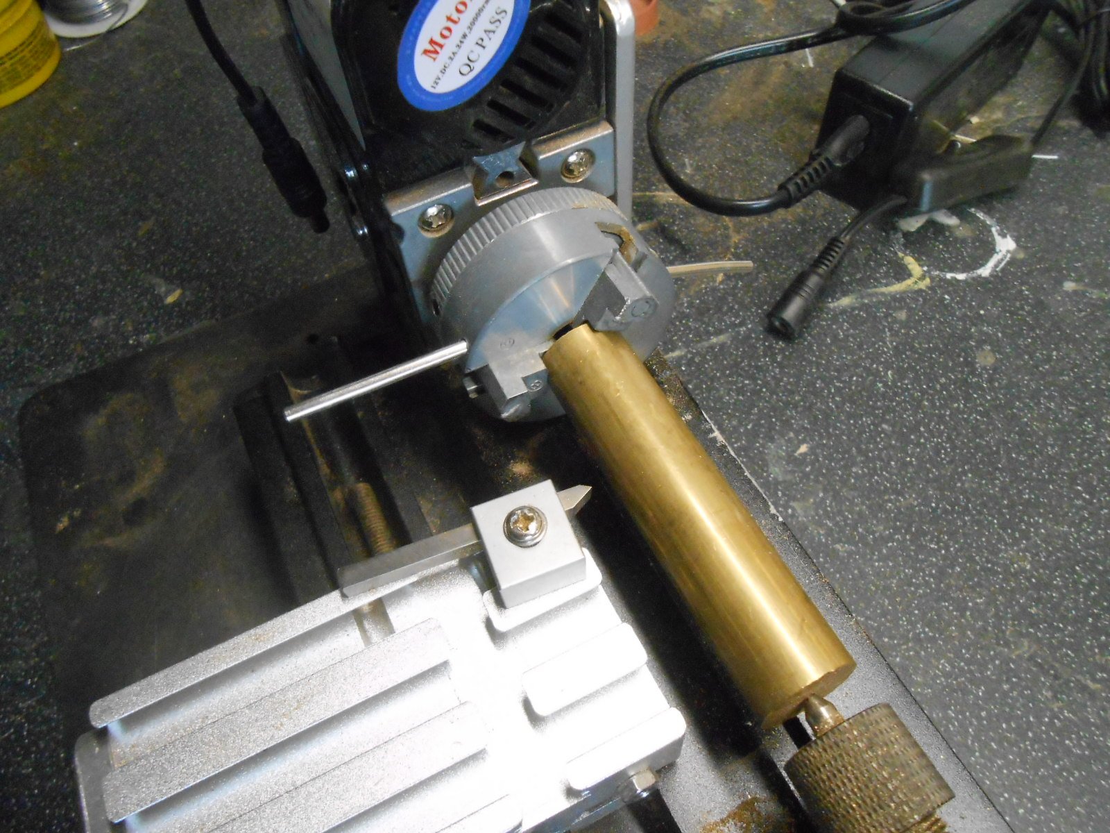
Anyway, turning a piece of solid brass into a dome or chimney is, for me, pretty much trial and error. The key tool is a vernier gauge, to transfer measurements from the drawing and then basic logic to decide which sections need doing first, though clearly you start at the outside and work inwards.
I've got a small selection of cutting tools, but also find files very useful. Otherwise, it is a case of taking my time. The lathe motor isn't very powerful, so you can't remove much metal in each pass - probably no more than a 0.25mm, but after an hour or so of passing to and fro, the shape I want gradually emerges.
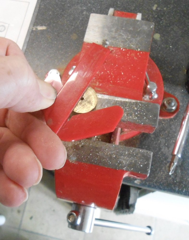
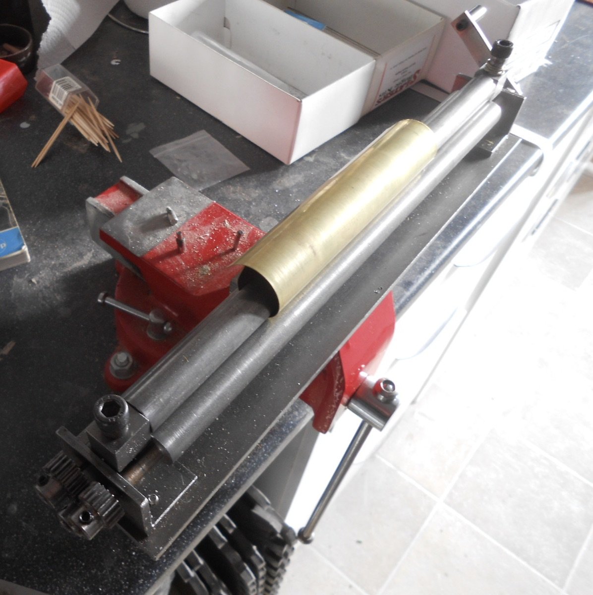
Once satisfied, the piece comes out of the lathe and it is cut from the original rod with a hacksaw [in a vice], after which comes the somewhat taxing job of filing the base so chimney/dome sit nicely on the boiler. The top of the chimney needs drilling out, of course, done in the usual way be starting with a small drill and gradually using larger ones to achieve the right sized hole.
Chimney and dome can be seen below, perched on the loco, but [as with everything else], not yet fixed. That will be the next stage!
-
11
-
5
-
-
I believe the correct term should be 'spring drive' - or something like that. I think 'clockwork' was seen as being toy like, whereas models like these are marvels of miniature engineering.
Some of the spring drives were pretty powerful and driving them was akin to live steam in some ways, while such was the efficiency/predictability of the best mechanisms that you could be fairly optimistic that a set number of turns of the key would give you a specific length of run.
Whether spring drive would work on the small, terminus-fiddle yard layouts of today is another matter. Will these wonderful models be visiting Enniskillen as some point? It is a great place for some photos!
-
2
-
-
My word, they look stunning! Give every impression they would be happy on fine scale track too.
The bubble wrap needs to come off the S so it can be fired up immediately - though suspect it's a bit more complex than that...
Was in a junk shop in Rye today, idly musing over some Hornby tinplate. Horribly crude, but not without charm. These models compare very well with the best that is available today.
Looking forward to finding out more.
-
3
-
-
Thanks Paul. Not a million miles away, but if I ever do a 4-8-0, there will be no excuses!
-
1
-
-
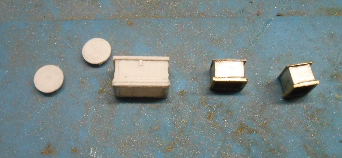
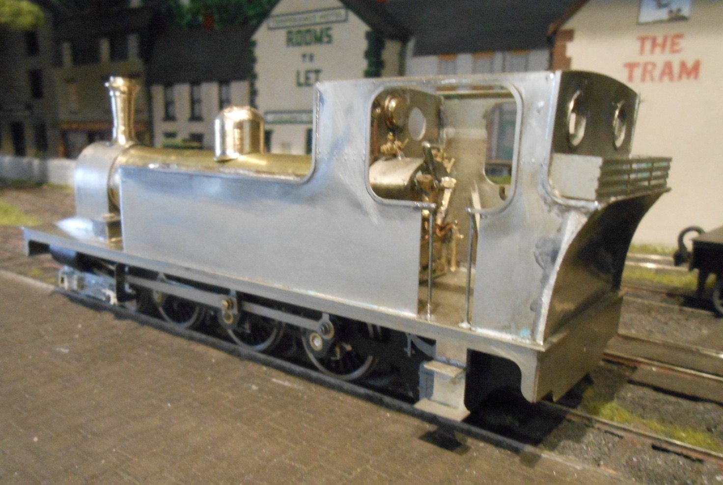
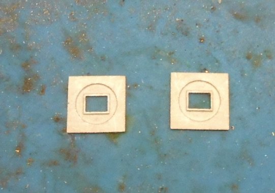
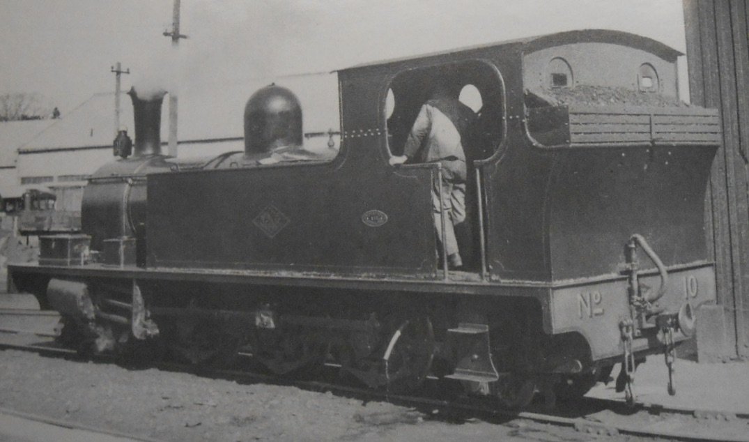
Pretty much used up all the etches this week, so everything else on the loco is now scrapbox or scratch building. There were two small square etches that I had no idea about until I finally came across a picture of No 10's bunker and there they were.
Other etches make up the firebox, sandboxes and cab steps, while the bunker extension etch includes some neat points for using the rivet press.
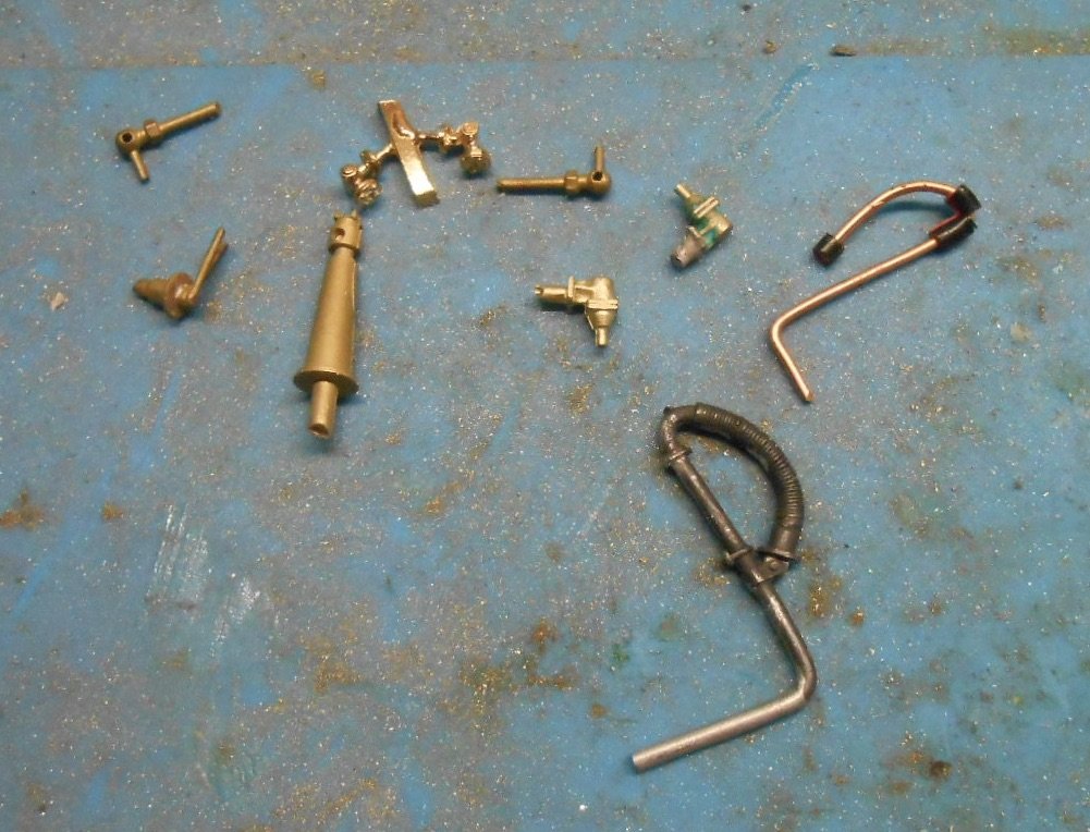
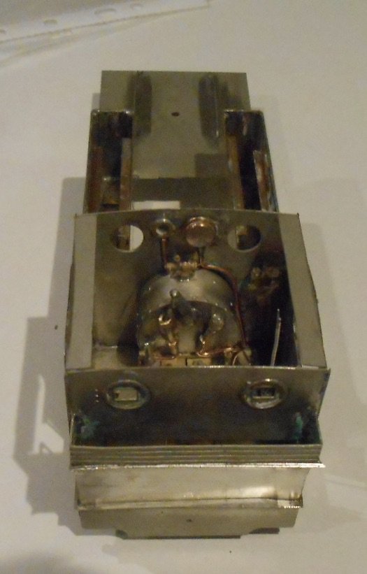
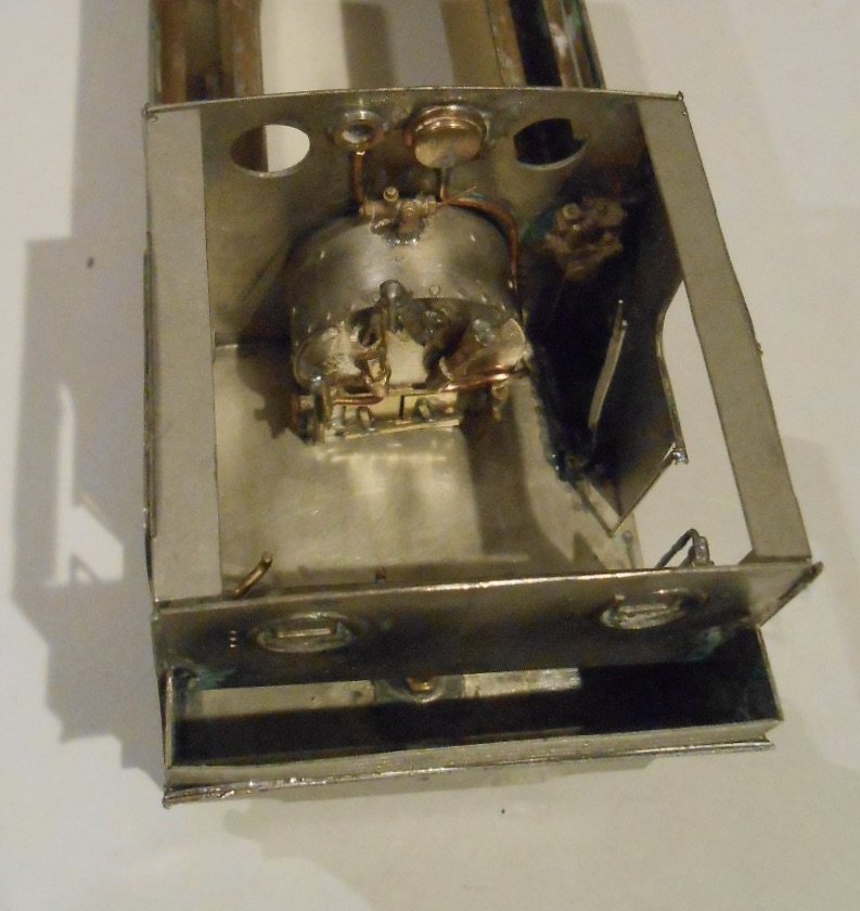
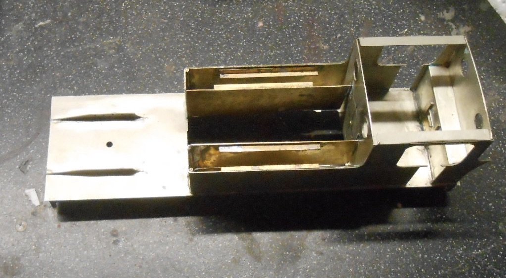
Inspired by Galteemore's recent post on the PP's cab, I spent a mostly happy morning today, cobbling together bits and pieces for the firebox and other controls. Nothing fancy, as only a representation is needed, given that it will be a pretty enclosed space, especially once the crew and roof are in place.
I found a few useful castings in the scrap box, while a brass washer was used to make one of the gauges. Copper wire from multi strand cable makes the pipework, while a cut down point lever suffices as the reversing lever. Looking through photos, it appears that Swilly locos were right hand drive, with lever, rather than screw reverse, though am happy to stand corrected.
The list of details runs to at least 30 odd items, so lots still to do!
-
9
-
3
-
-
A not dissimilar experience last time my wife and I went over the pond, saw us arrive at Boston Logan Airport early, only to be held on the tarmac for nearly an hour & then when we finally made immigration, we had to wait another hour while they let all the US passport holders through first! And it was still another half hour before we got our bags...
-
10 hours ago, Galteemore said:
Hi David - I used some square plastic rod, coupled with whitemetal valve parts from SD Models. The tube has a core drilled through it which nicely replicates the gauge glass inside the shroud. White plasticard backing with chevrons completes the look.
Clever!
-
Very fiddly, but very worthwhile, especially on a tender engine. Handy reference for me because am starting to do the same job on my Swilly tank.
Intrigued to know what you used for the gauge glasses? I usually cheat and paint square section brass a silver colour, but yours looks far more effective.
-
If they are still available, Smiths three links were a good option. They have a slightly larger than scale hook to ease operation.
-
 1
1
-
-
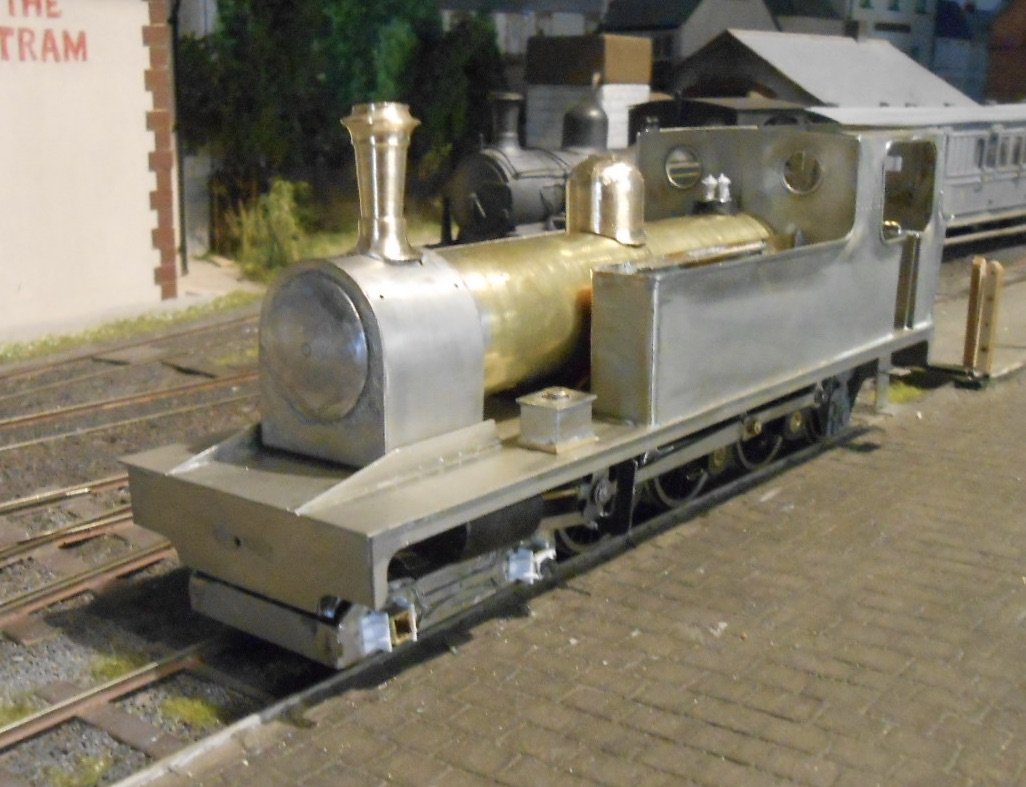
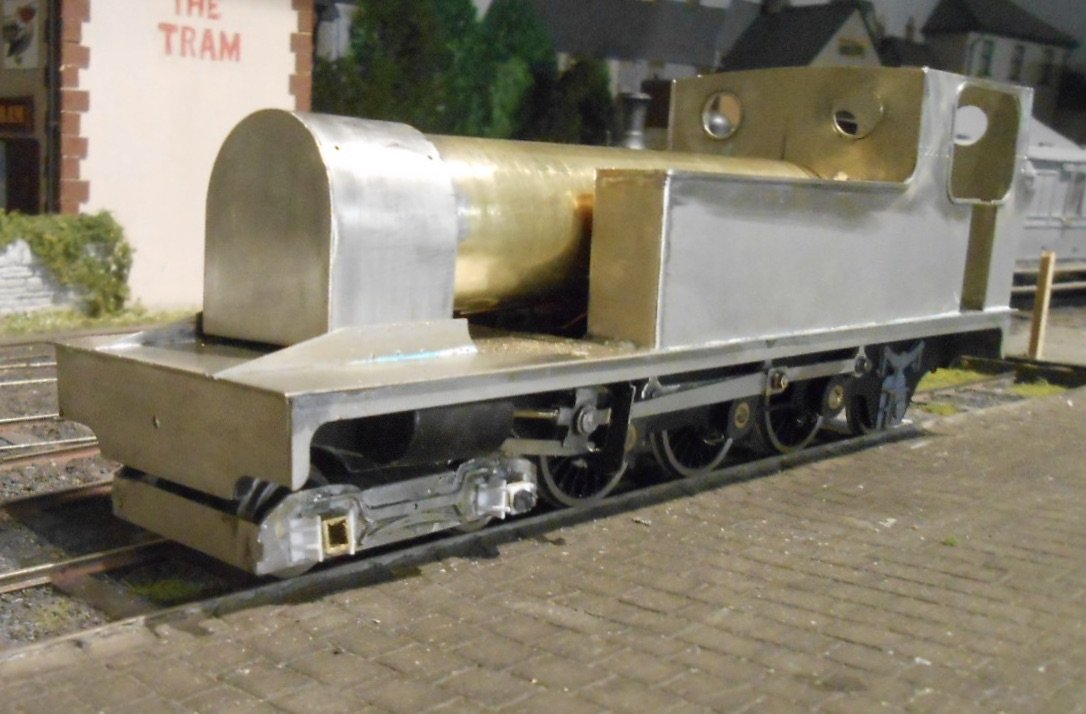
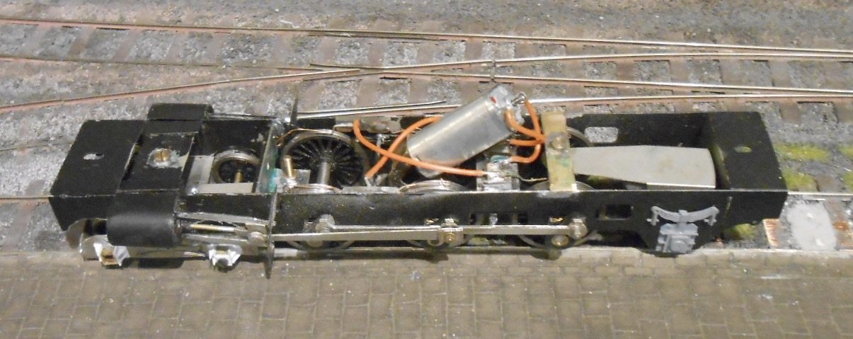
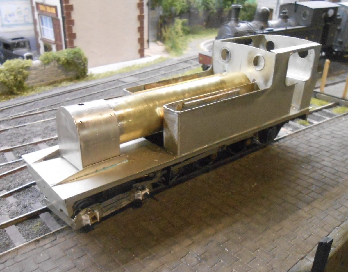
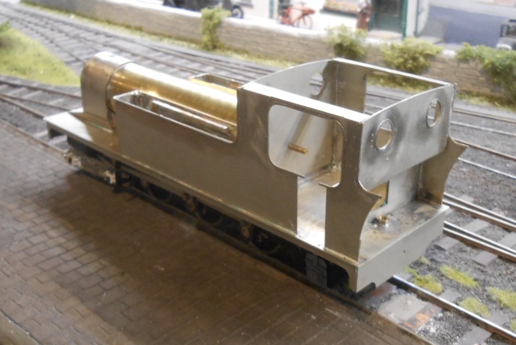
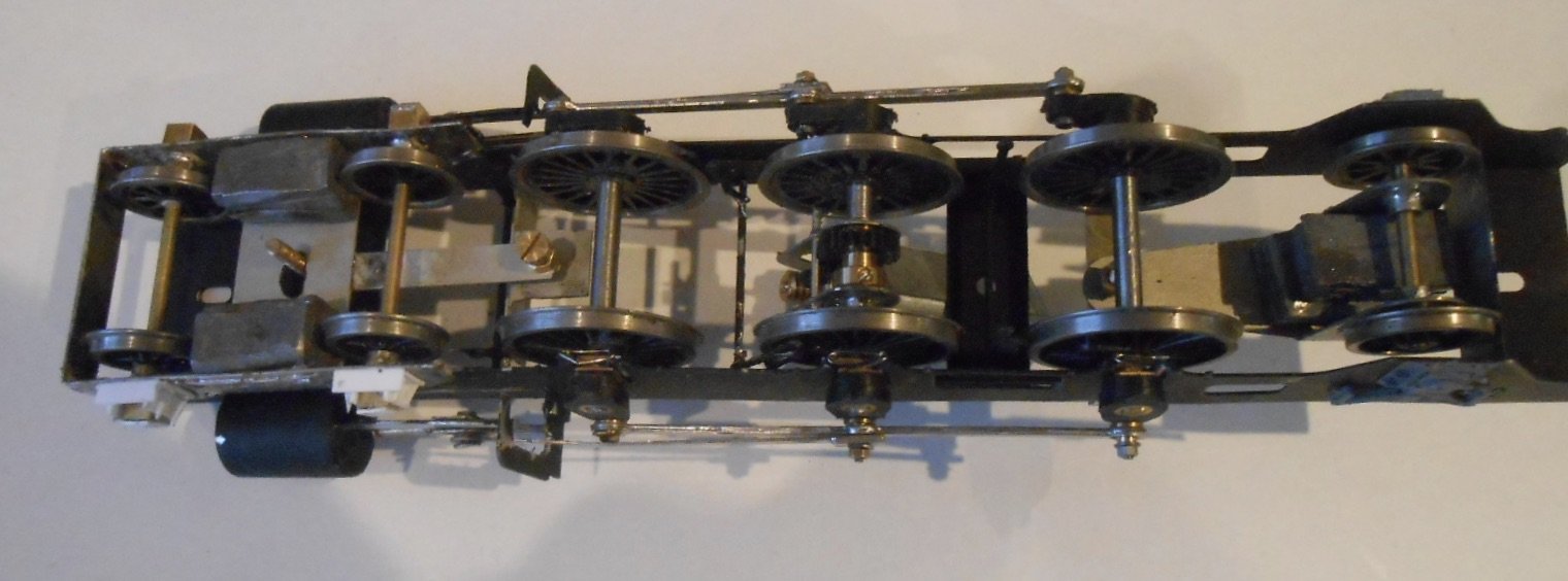
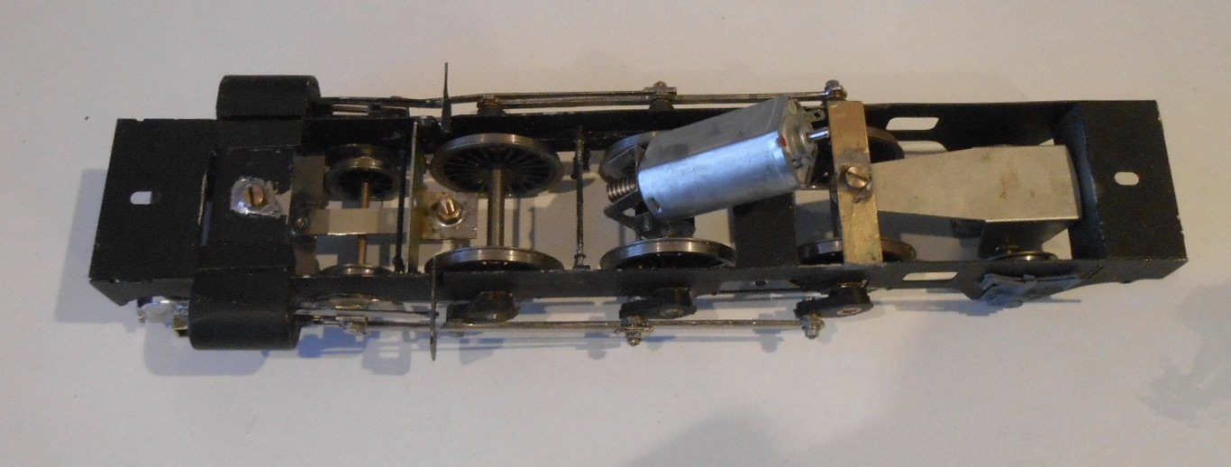
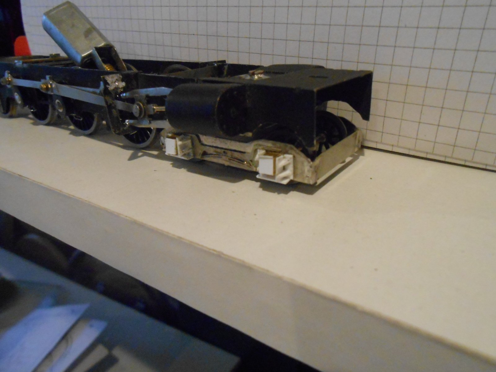
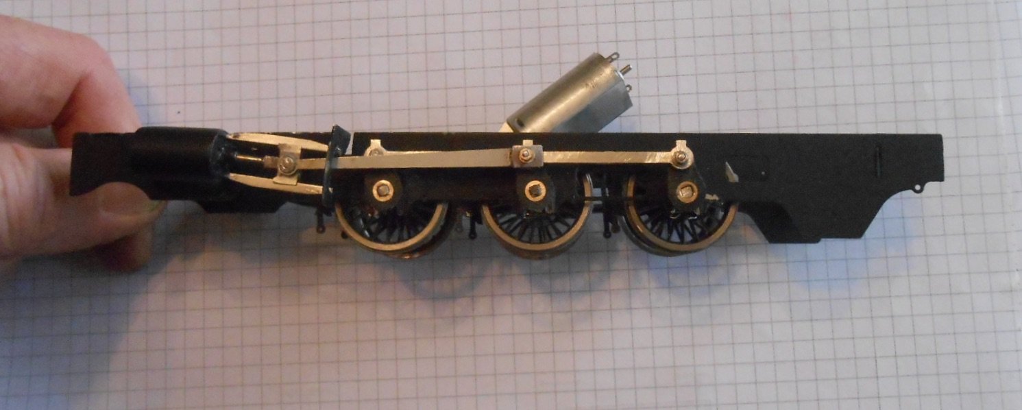
Starting to look like an engine
First job this time was to fit the motor and pickups. Normally make up the latter as I go along, but this time I actually thought about it first and soldered both the pickup and electrical wires on [2 different temperature solders], before gluing the copper clad to the frames. A frame spacer means the latter is split in two for each side, with a further piece on the frame spacer to take the electrical wires on their way to the motor. This part meant that when I got the polarity wrong [only 50-50, so why do I do it every time?], I didn't need to unsolder the wires from the motor terminals and risk damage. I've also used the wire runs to hold the motor in place, as seen below.
The pick ups still need adjusting, but the chassis runs ok now under its own power.
So, back to the bodywork.
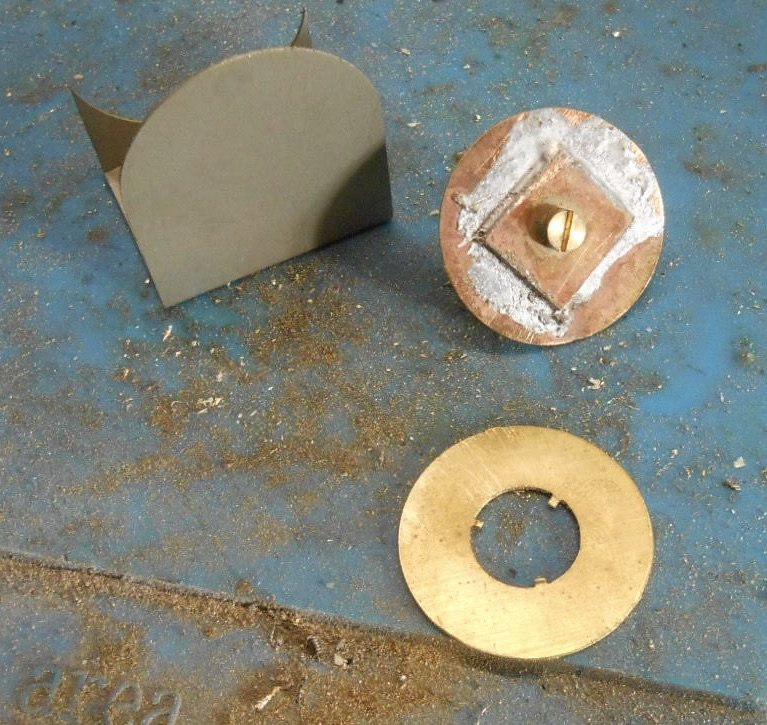
No boiler is supplied as part of the etches, so it was a case of rolling my own. This is where a GW Models Rolling Machine comes in so useful. In the scrap box, I also found two brass discs of exactly the right size to use as inner formers for the boiler. Soldered some brass strip in the centre to take an 8ba bolt for lining the firebox end up with the cab front.
Next was making the inner sides for the water tanks. Just rectangle of 15thou brass, though I added a couple of additional bits of brass to the inside faces to rest the tank tops on. A piece of round brass rod went in the inside front corners too, so these could be rounded like the outer corners. The tank tops won't be fitted until after I know how much lead will need adding to help adhesion.
The latest piece to be done is the smokebox. This is a single fold up etch, plus the wrapper, which needs rolling to shape. Happily the latter is just a half circle with straight sides - so no nasty reverse curves to form. Soldered up, it proved to be slightly bigger than the boiler, but by adding a wrapper to the end of the boiler [one millimetre longer than the smokebox, so it protrudes slightly, it works out pretty well.
Nothing is fixed in place yet, but the main superstructure is shaping up. A long way to go yet though, with the firebox and cab details, coal bunker and a host of other details including all the boiler fittings too.
-
11
-
3
-
-
On my.
When I saw the name and the first pictures, had to look back and then saw those fabulous bridge scenes, realising it was THAT layout and therefore the new stuff was also going to be something special.
Beautifully observed, splendidly subtle and a very fine creation. Well done!
-
2
-
-
Great to know this fine layout has been rehoused on the right side of the water.
-
4
-
-
Especially like the low level shots and the ones through the railings.
-
1
-
2
-
1
-
-
On the larger island, ever since privatisation, the issue is largely one of 'nothing spare'. Each franchise has just enough stock and it seems they don't share either. Hence, any failure leads to cancellation(s). Back in BR days, there were always sidings full of spare stock, which largely came out for summer specials, while it seemed there were a couple of spare locos at most bigger stations that could be called upon to act as pilots for an ailing train engine.
As a small child, remember being taken to see the Irish Mail go through Colwyn Bay, hoping to see a 'Lizzie' in charge, only to find it was running late and with a 4F 0-6-0 up front!
-
2
-
-
Love how ornate the early ones were, with fancy lettering and buttons. Shades of footmen for the rich and well heeled.
From a modelling point of view, it is the basic colours that matter most. Don't suppose there's a list/guide available?

-
1
-
-
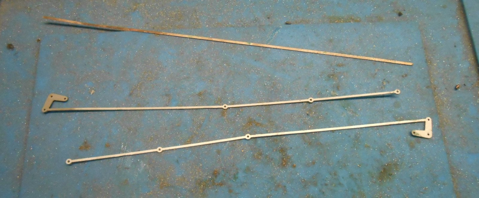
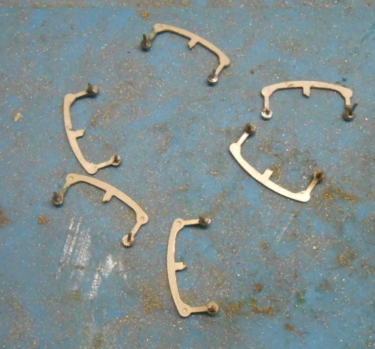
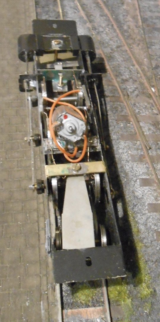
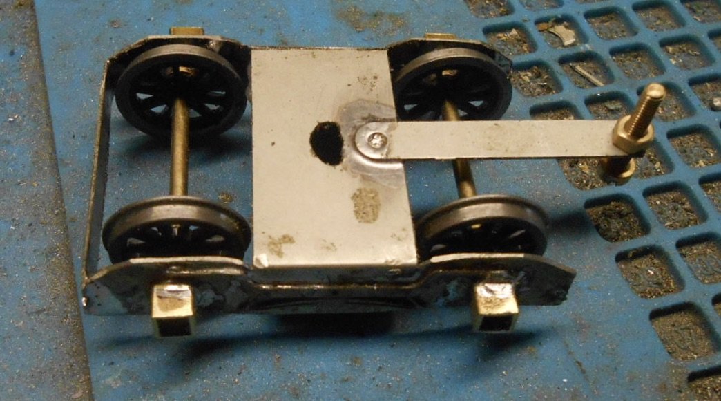
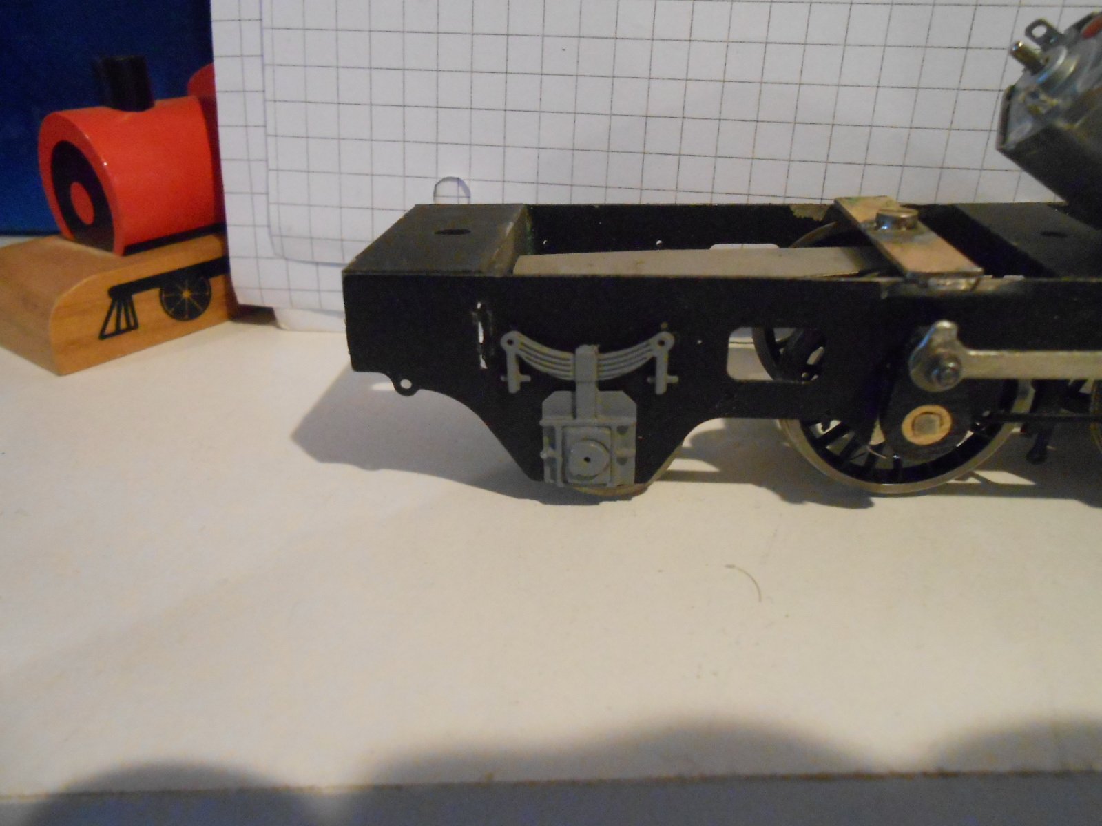
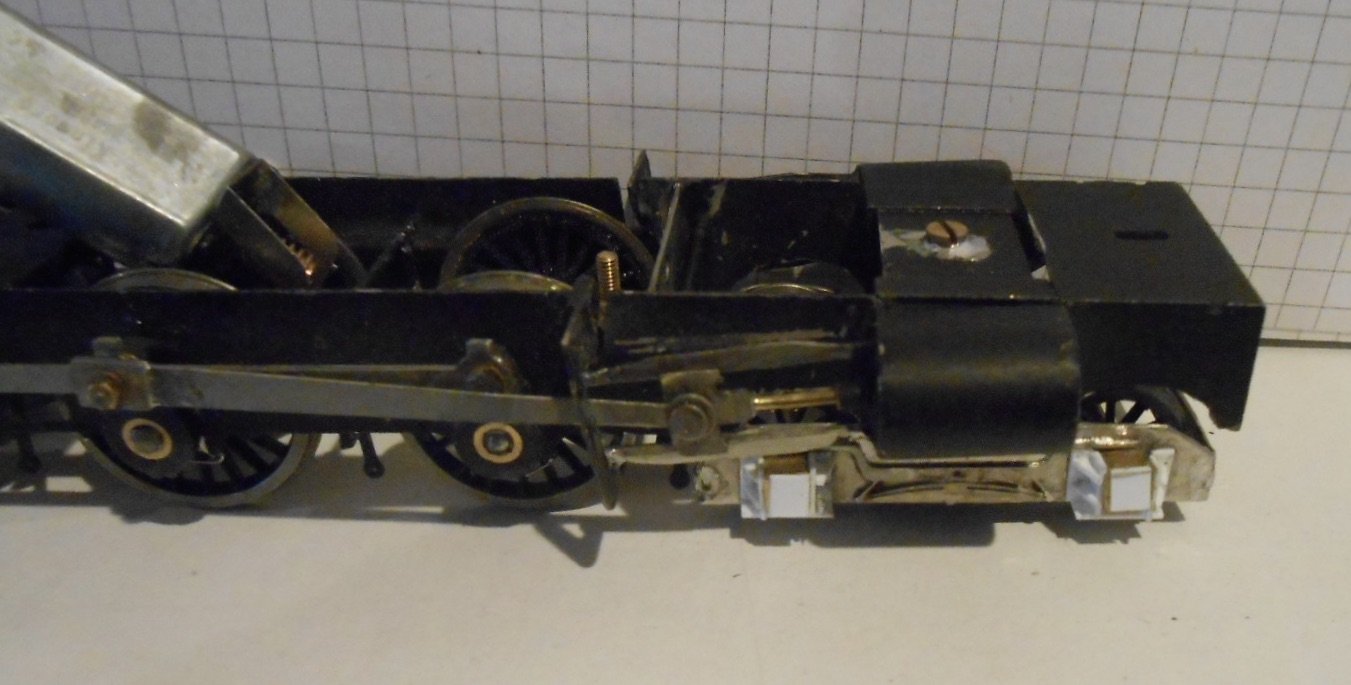
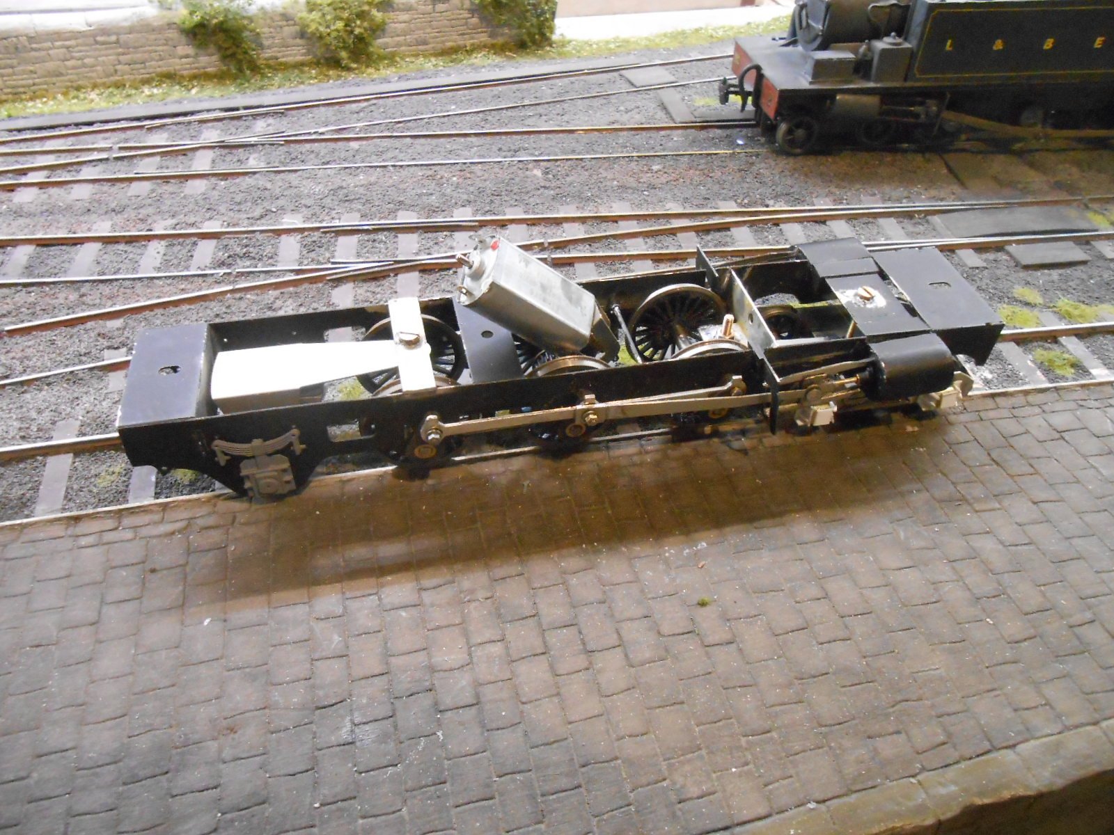
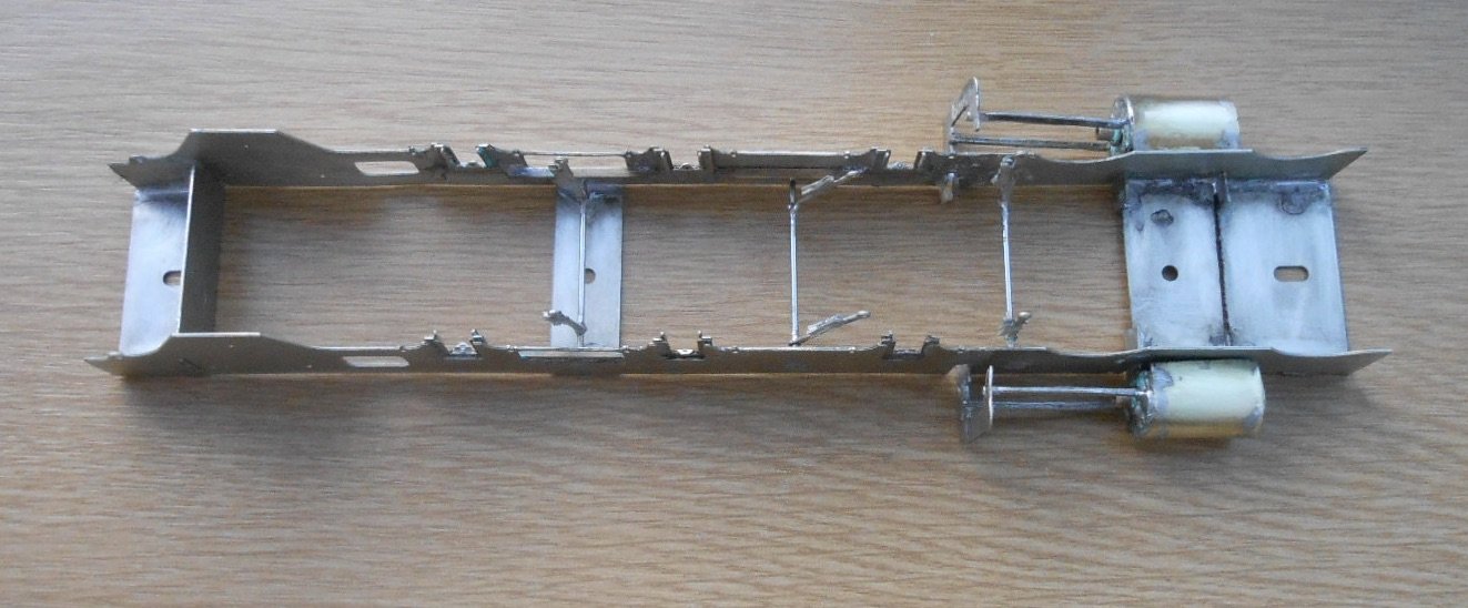
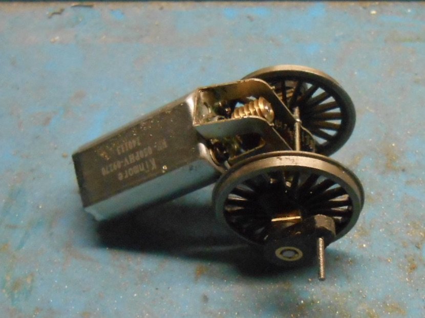
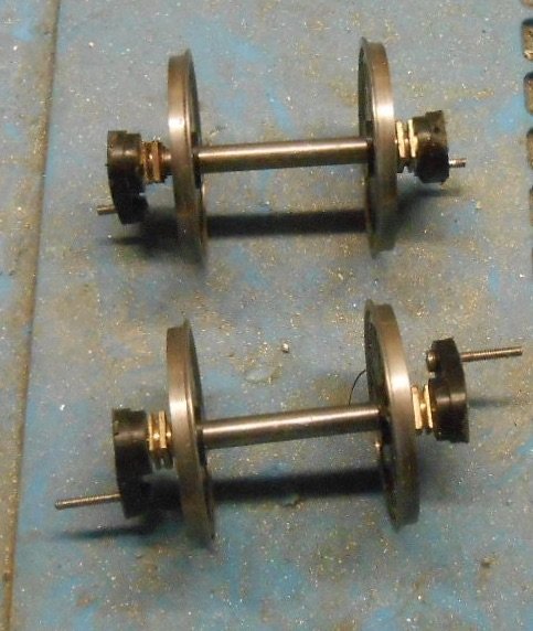
Bogie and Pony
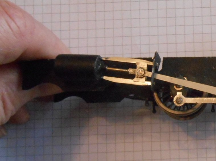
Not an interesting name for a pub, just the next stage in the Kerr Stuart's chassis, with a fair bit of faffing and fiddling along the way. Both units are simple fold up etches, though in the case of the bogie, one side broke off while I was folding it. Not to worry though, because it turned out that it was a tad too wide, so I filed a bit off before soldering it back.
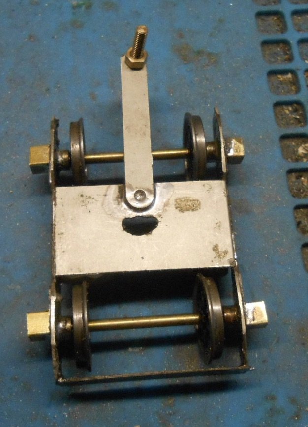
The Gibson wheels are on 2mm axles, so it was just as well I had some 2mm brass wire, along with the right bearings. The outer plate, on the left. is intended to fit in slots on the side frames, but doing this means it fouls the wheels, so had to adjust that. The etches have a bogie pivot plate, so that was soldered on, as were four pieces of square section brass tube as part of fabricating the outside axles boxes.
There are several spare frame spacers in the etches, so used one of these as mounting point for the bogie swivel, putting it just in front of the leading drivers. Notice how the bogie frame spacer has a slot filed in it. This is to go over an 8BA bolt soldered in the main frame spacer.
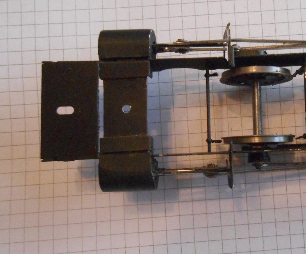
Tried using another spacer for the pony swivel, but this fouled the rear drivers, so made a new one from some brass strip, which sits on top of the frames, just clearing the rear drivers. Looks like I'll need to line the inside of the frames with 10thou plastic to avoid the pony wheels shorting out. Both bogie and pony are full of lead, hopefully to help them stay on the track.
At the moment, both units appear to sit nicely, but no doubt adjustment will be needed. Indeed, already had to cut away sections of the front frames to clear the bogie wheels.
On the real locos, it looks like the pony wheels lived in some sort of radial axle boxes. On the model, they pivot inside the frames, with etches enabling you to build up dummy axles boxes on the outside of the frames. There are four separate layers to give a nice bit of depth.
Was hoping to find some white metal castings to represent the outside axle boxes on the bogie, but couldn't find anything suitable, either on line or in the scrapbox. So went back to John Ahern's book for ideas & realised that with that square section brass tube & some plasticard, I could make a reasonable representation, as shown below. I could do with thickening up the dummy equalising beam between the two boxes, as this looks a lot heftier than a single layer of nickel silver provided in the etches.
Anyway, so far, so good, though I'm not kidding myself that it is all going to work first time of asking. Need to fit the pickups and wire up the motor first, but at least there is plenty of space to fit these and likewise room in the bodywork for extra weight if required. For now at least, the chassis appears to sit nicely on the track.
-
4
-
4
-
-
That is just lovely.
-
1
-
1
-
-
Thanks John and also useful to see how you arrange the bogie and pony swivels too. Reassuring to know that folk with your experience and expertise also have these challenges. Did wonder if I'd need to reverse the crankpin bush, but there is just about enough room - with a slight crank to the conrod.
At least the position of the bogie on the Kerr Stuart is largely out of the way of the cylinders, because it is inside the frames, though as the next job, that may yet try to bite me.
Hats off to the P4/S7 and 2FS folk. Really can't contemplate working to such fine tolerances!
-
2
-
-
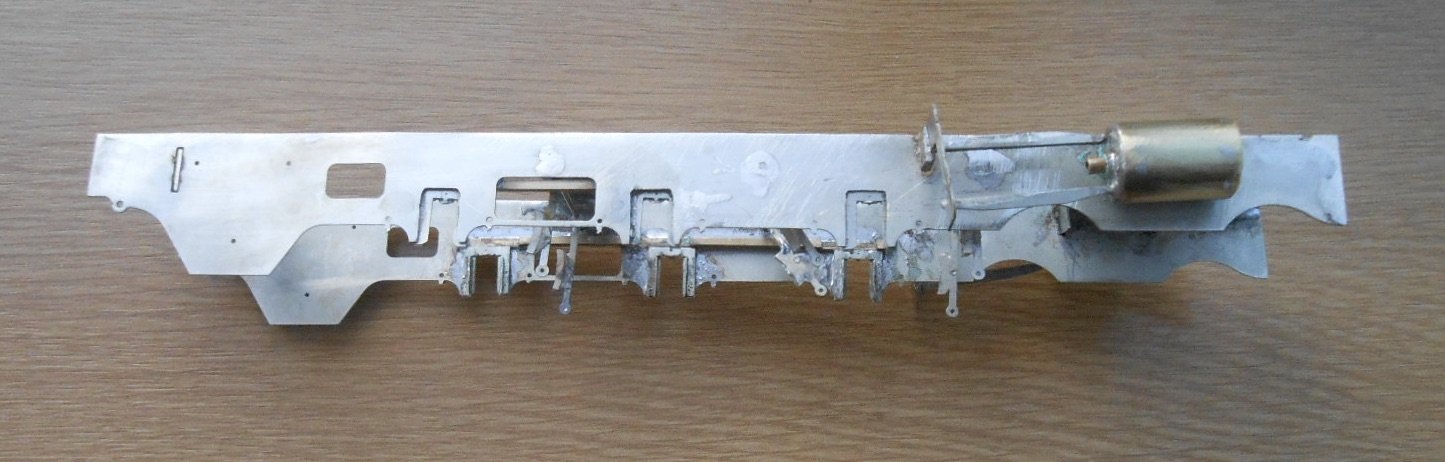
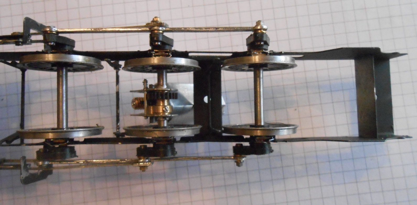
It's been a hard day's night - and I've been working like a dog. Well, not quite, but I do at last have a smoothly working chassis for the Kerr Stuart.
After that previous post, I sat down and made a list of all the things that needed attending to, then stripped everything off the chassis to go through it all bit by bit.
Started by moving out the slidebars, so the crossheads would not foul the leading crankpins and at the same time moved the position of the motion brackets forwards so the crankpins didn't foul them either. While I was at it added the cross wires for the top brake hangers, leaving the latter loose until the wheels were fitted.
Thought it was time to add the motor to the gear box and then refitted the wheels, adding the retaining wires to the horn blocks, so nothing falls out.
I'd hoped to add the etches depicting the actual horn blocks, but even after significant thinning down with a file, there just isn't room, so they will have to be omitted. Fortunately, the cranks will mostly hide this, especially with everything painted black. Did drill holes for the underslung springs to eventually be fitted.
Before this, I'd sprayed the chassis with primer & then matt black
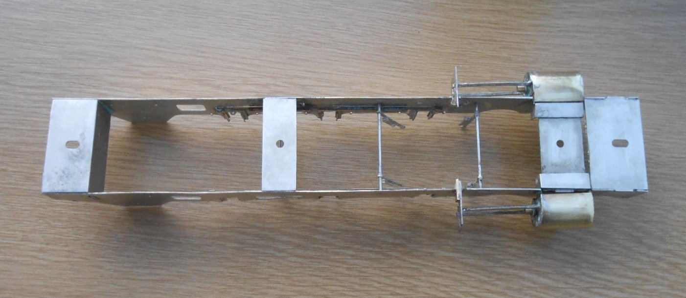
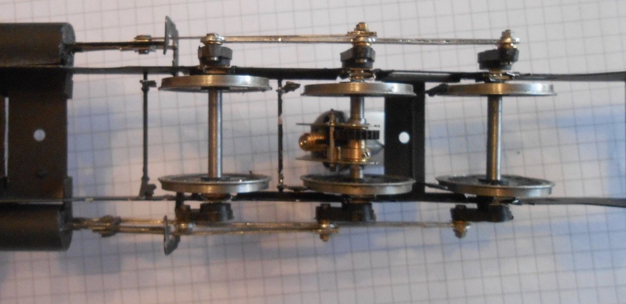
So far, so good, but that was the easy bit, as the last week has been spent fettling and fine tuning the chassis. As I'd said earlier, clearances are tight all over the place.
The slidebars need to be set so the crosshead works smoothly and doesn't foul the motion bracket and the piston rod doesn't hit the cylinder.
Fag paper clearances here, as shown above.
The front crankpin nuts needed to be filed really thin, with the base of the crankpin bearings similarly thinned to a minimum. Both the front and centre cranks are fitted close to the frames, to give minimal side play. The rear cranks allow about a millimetre each each way and this also helps the fact that the slide bars have had to be set so they are gently angle away from the frames - again to clear the front crosshead. This at least allows the piston rod to be in the centre of the cylinder, the common alternative to this is to place it off centre.
Annoyingly, despite the coupling rods working nicely on the ends of the axles, once the cranks were fitted, things got tight, so a lot of time has been spent gradually opening out the holes in the rods, which meant repeatedly taking them on and off - risking the wrath of the carpet monster should I drop any of the 12ba fixing nuts and washers, both of which I have very few spares at the moment!
Finally, about 5pm this afternoon, everything was at last running smoothly. The temptation to pour a stiff drink and then lie in a darkened room for a while was considerable!
-
8
-
1
-
-
Took hours to get that squeak right! Was it really that long ago and I obviously didn't know of your models at the time, Alan, otherwise operations would have to have been suspended while I learned more.
-
2
-
 1
1
-
-
Forgot about both of these. Shame on me, as I have both! Excellent books.

London Road Models
in General Chat
Posted
Amen to all the above!
We are all still learning, but those early stages are important. Success breeds confidence which is why buildings and scenery are easier that wagons, which are easier than coaches and are best before tackling a working loco.
Some locos are easier than others, with maybe an inside cylinder 0-4-0T the most straightforward. Add another pair of axles and things ramp up a bit as the capacity for rods to bind increases, but an 0-6-0T is still a worthy starter. In 7mm scale, Jim McGowan's Connoisseur kits are hard to beat, though an Alphagraphix MGWR J26 is a great starter too. The chassis is a one piece etch, where you solder in the bearings before folding up the sides and frame spacers. You can have a rolling chassis within an hour or so - very good for morale!
Avoid being tempted by a favourite loco as a first attempt. Anything with bogie or pony wheels, outside cylinders, let alone outside frames (sounds familiar), is a nightmare waiting to happen. However, by starting simple, building up your skills and knowledge, there is a lifetime of satisfaction ahead. Whatever their imperfections, they are your models, not something plucked from a shelf and a coat of paint covers a multitude of sins.