

David Holman
-
Posts
4,154 -
Joined
-
Last visited
-
Days Won
114
Content Type
Profiles
Forums
Resource Library
Events
Gallery
Blogs
Store
Community Map
Posts posted by David Holman
-
-
Great to see this progressing. Certainly looks like somebody knew what they were doing re initial construction, so looking forward to seeing it completed. NPQ booked again for Aldershot in October. A parcels special via the Burma Road?


-
 1
1
-
 1
1
-
-
Well, the little Tamiya drill has proved its worth in drilling holes in plastic for hand rails, though it will work even better when I get some sharper bits.
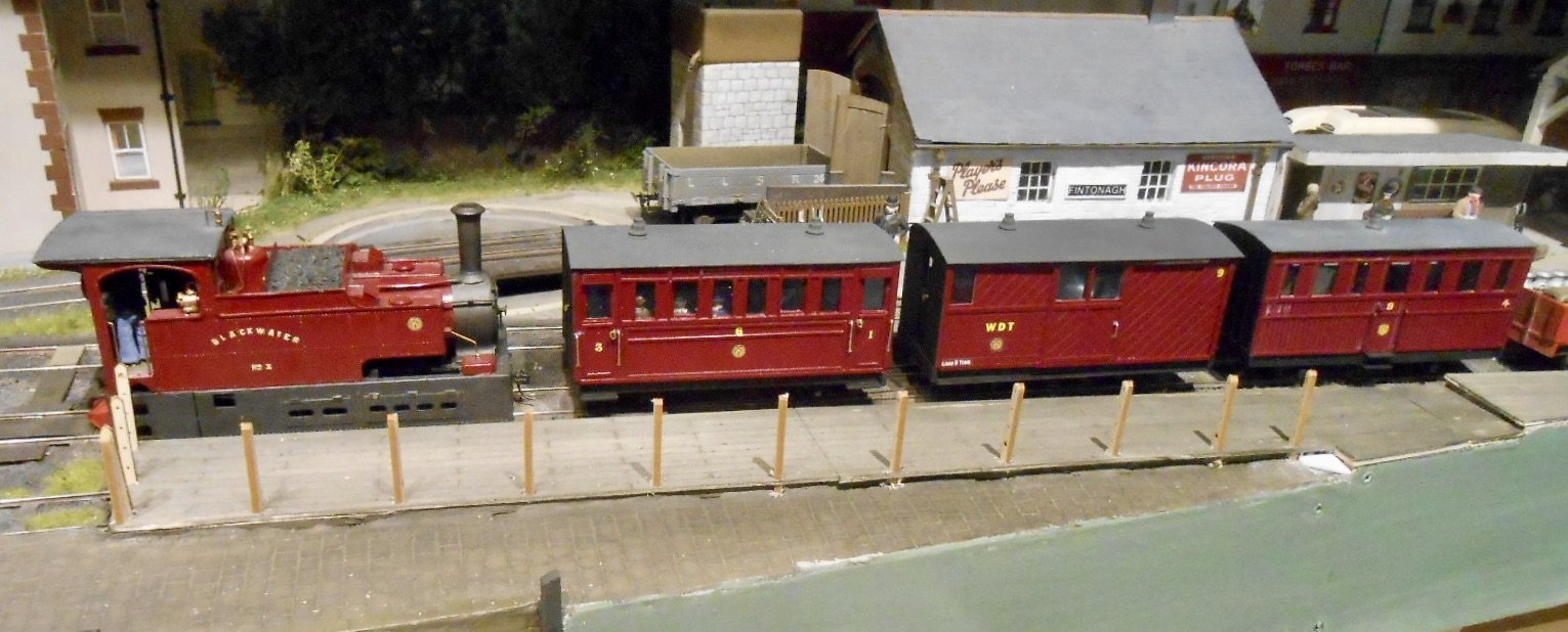
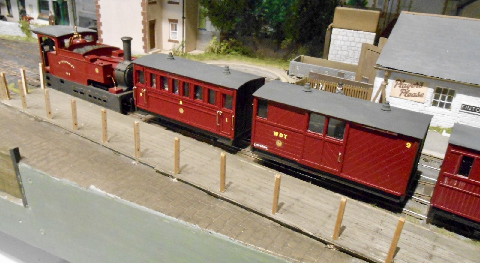
Anyway, certainly helped me move the tramway coaches towards completion. Couplings needed [still to grasp the nettle here], but painting and lettering finished today, along with roofs and interiors beforehand, including some cheap and cheerful Peco figures.
Lettering is Fox and the crests are LMS from and old SMS transfer sheet. Use the crests for my Donegal stock too, though for the West Donegal Tramway, have put them upside down. The crests also nicely cover up the Clogher Valley logo on the loco.
As you can see in the photos, work has begun on the fencing for the tramway platform.

-
11
-
 4
4
-
-
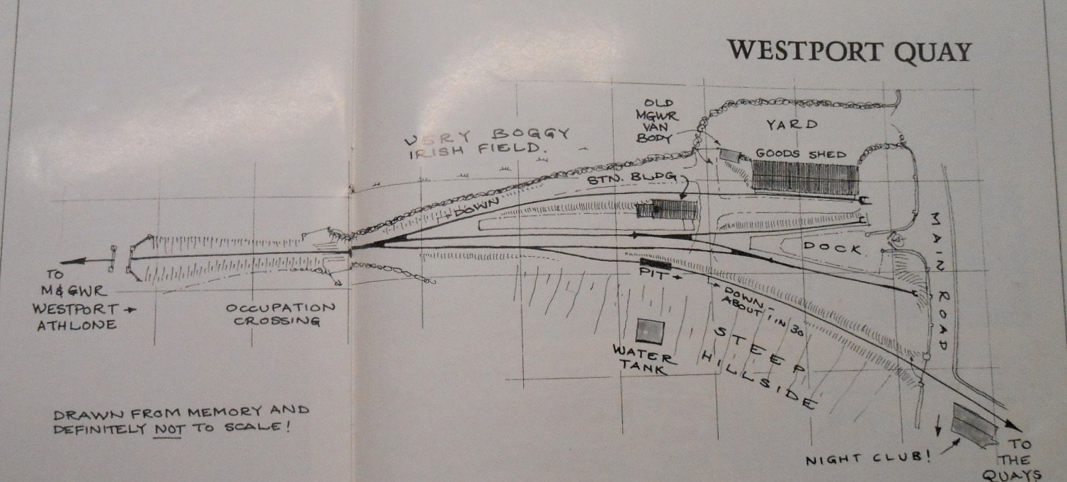
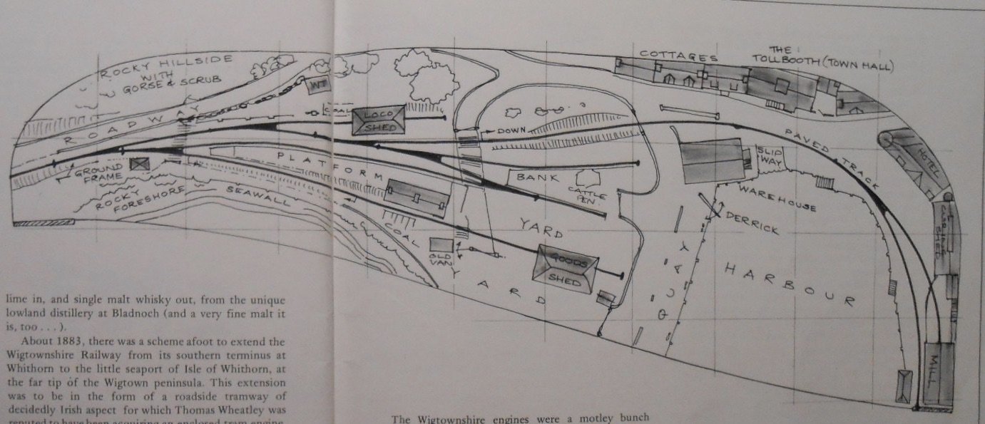
Nice! Westport Quay worth a look too. Iain Rice did two takes on the subject, as shown below.
-
4
-
 1
1
-
-
Or extend the life of the Burma Road for a few years, maybe? Loco hauled trains, often only a couple of coaches long. There again, fictional locations can be anything you like.
-
1
-
-
If you haven't already, check the Patrick's Layout thread, on page two of this section. Shows just how well a simple track plan can work by putting the railway in the scenery.
Certainly lots to inspire in those photos posted yesterday!
-
2
-
-
Planning is half the fun and I've scratched many itches that way, with 99% never making it off paper.
I think you have to balance the time, effort as especially cost, against how much value you place on having such space. Our roof is too low pitched to be any use, but did eventually convert the integral garage into my workshop, by fitting double glazed, hinged doors, and adding a radiator from the central heating system, plus an access door from the porch inside the house.
It has given me 16' of layout space down one side and work bench/storage on the other one and a half sides, using kitchen base units/worktops. The layout space gives room for two, one above the other and though they are only terminus-fiddle yard, they provide enough operation interest when the mood takes me. That said, I mainly build things and exhibit at shows, so though a continuous run would be nice, I doubt I would use it much.
-
4
-
-
Ordered one from Amazon Sunday evening, it arrived yesterday afternoon and put it together in front of the tv last night. The instructions took a bit of getting used to, but overall went together ok.
As an intermediate drill, am hoping it will work well with plastic sheet, where my Proxxon is far too fast and melts its way through. First test later today, fitting hand rails to the tramway coaches.
-
2
-
-
A classic case of it only being half a dozen pieces for the structure, but add in all the details and it becomes more than a bit complicated! The dinky size of the prototype can't have helped - overall, looks a lot shorter than a G2 and these aren't exactly giants.
As ever, very neat, very tidy and very, very good.
-
1
-
-
Yes, thought about Lima and there were/are several British outline locos in HO, not least 08 shunters in Dutch livery. Am guessing that, even with kit and body bashing skills developed by modellers of the Irish scene, the time and effort didn't make it worthwhile compared to doing 21mms gauge.
-
Browsing the 2025 RM Special, there is an article of a dual gauge Australian layout. Called Broadford, it is based on a real location, near Melbourne that has both 5'3 and standard gauge track, which the builder has nicely replicated using American code 83 rail for the latter and hand built EM the former.
Begs the question, has anyone tried to do Irish 5'3 in HO, on EM track? If they have, feel sure the good folk on this forum will know and provide details.
Challenge thrown down!
-
3
-
-
Just had to go back and check this is 00 track. Ballasting, weathering at really effective and certainly enhance the whole scene
-
4
-
1
-
-
Looks a very neat idea, an ideal middle path between a high speed mini drill and finger twirling a pin vice
-
1
-
-
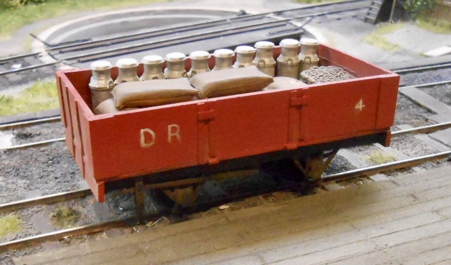
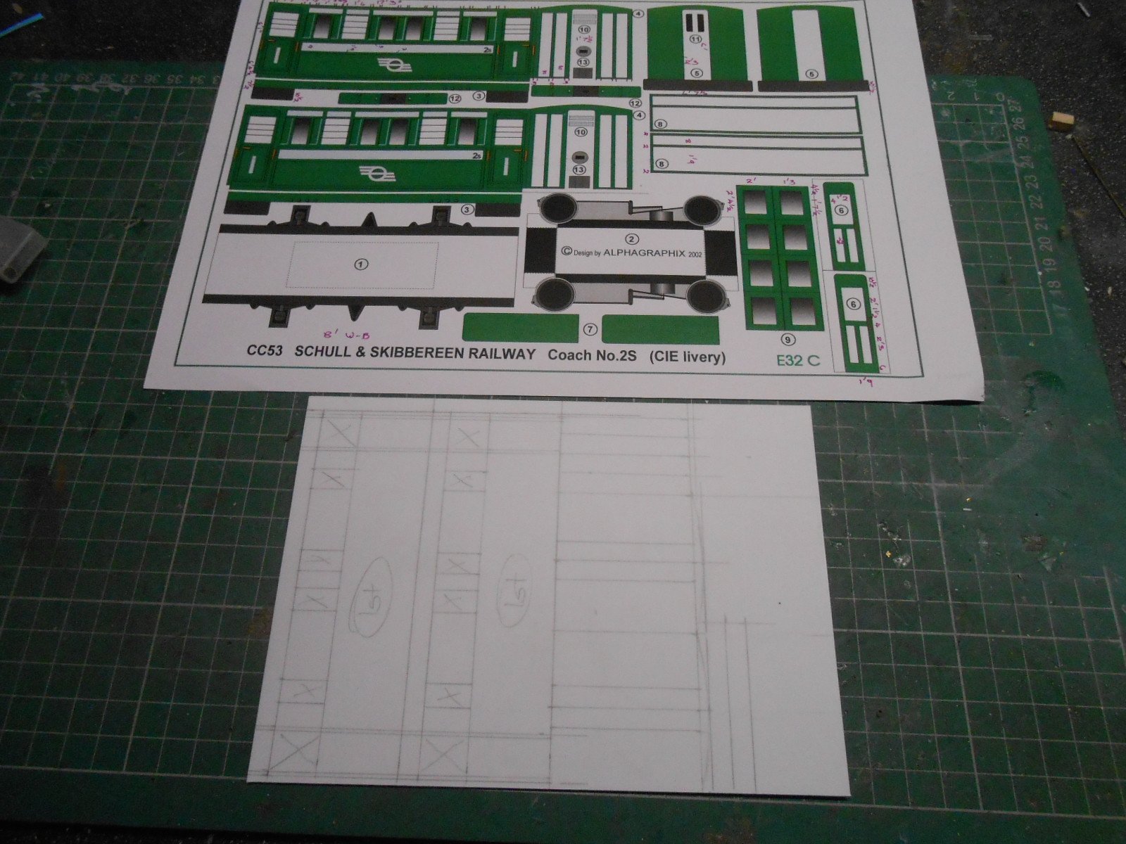
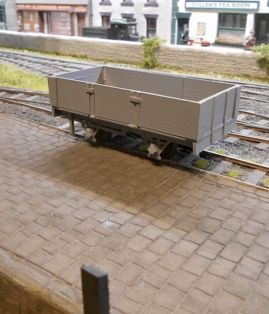
Been working on some rolling stock again. A Donegal 'red wagon' has joined the fleet, built from plasticard & based on the Alphagraphix card kit. The chassis is a suitably chopped etch intended for 4mm scale. Not sure if the wagon load will end being the one depicted, as much will depend on what Railcar 8 can pull. Which reminds me - must get in touch with Mark Clark as it is now at least six months since I gave him the bodywork in the hope of a working chassis...
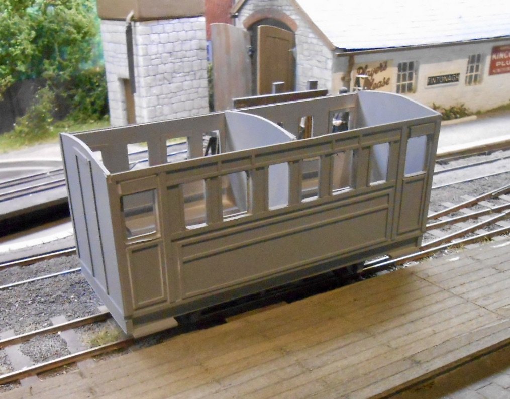
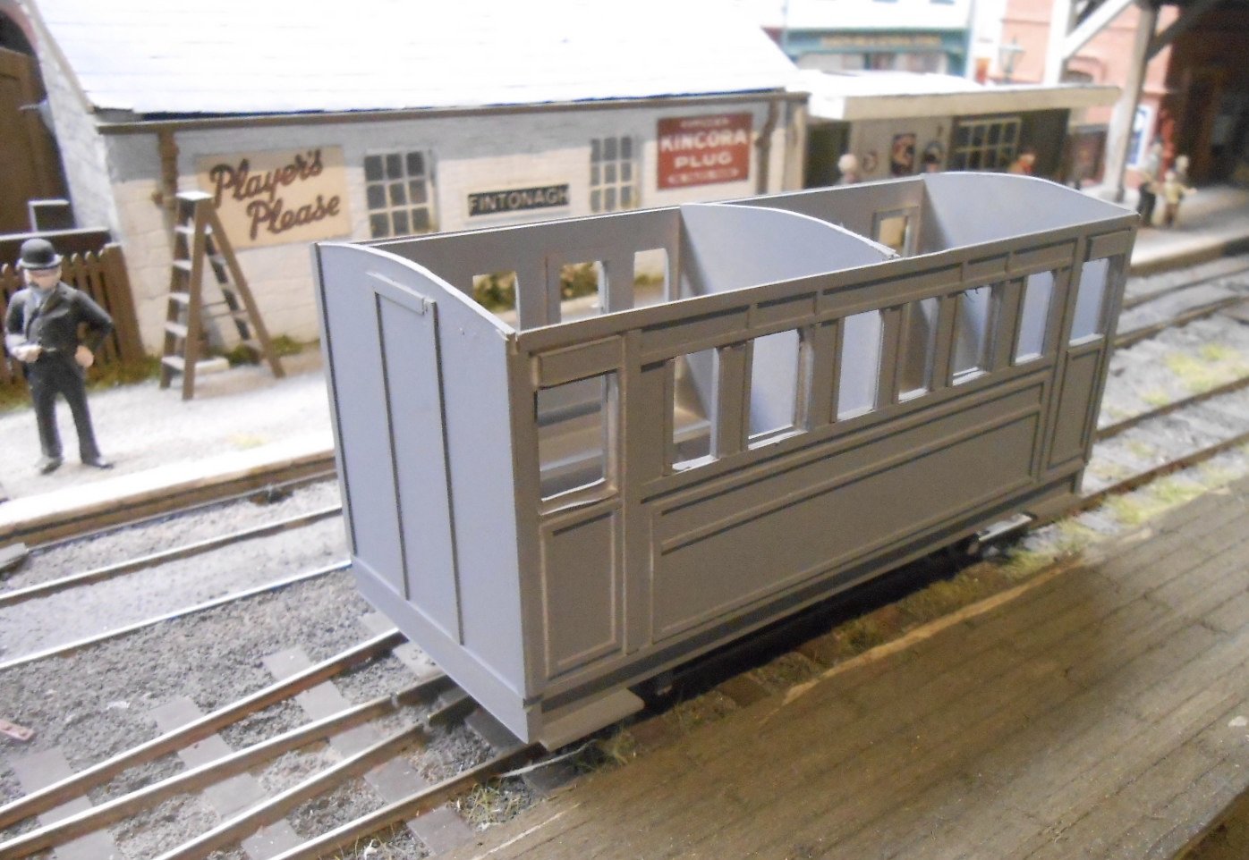
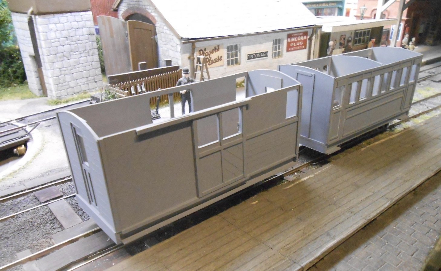
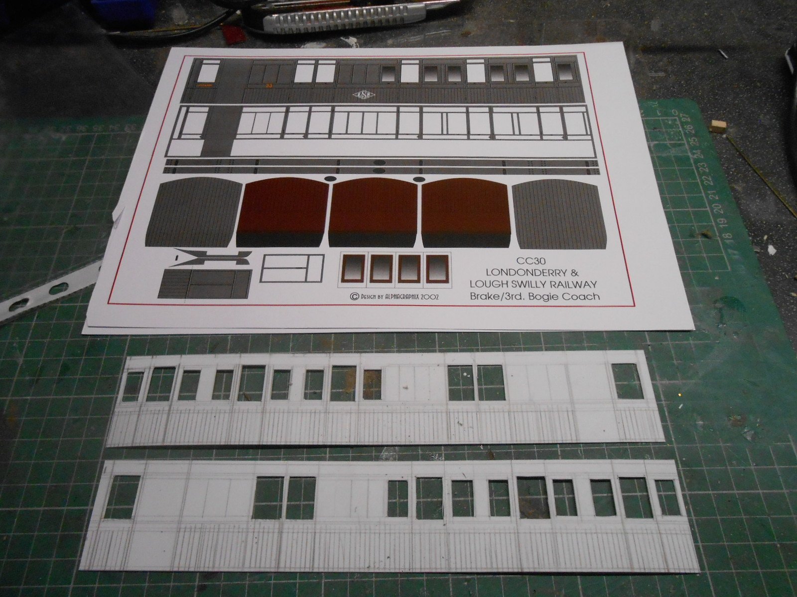
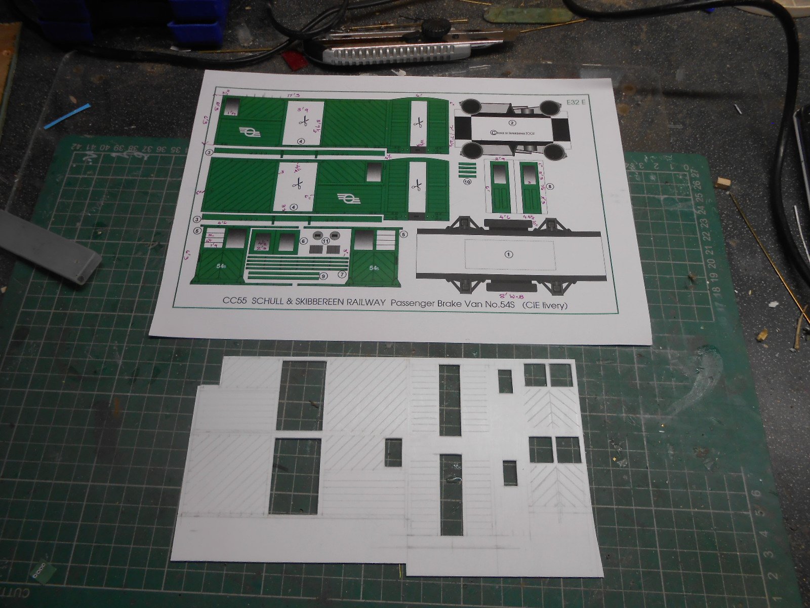
Next come the other two tramway coaches. Based on the Alphagraphix card kits from the Schull & Skibbereen, have increased the width of these two to 6'6 as the 3rd class coach looks a bit narrow at just 6'. One is a passenger brake van, the other a first class coach, now downgraded to a third, but retaining smoking and none smoking sections.
Plasticard all round for these, including the chassis which are doctored Parkside ones - a real bargain at less than six quid.
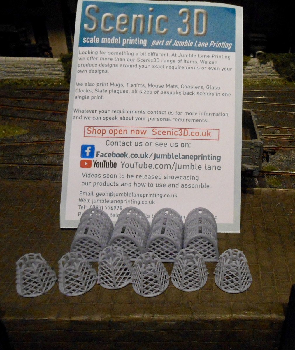
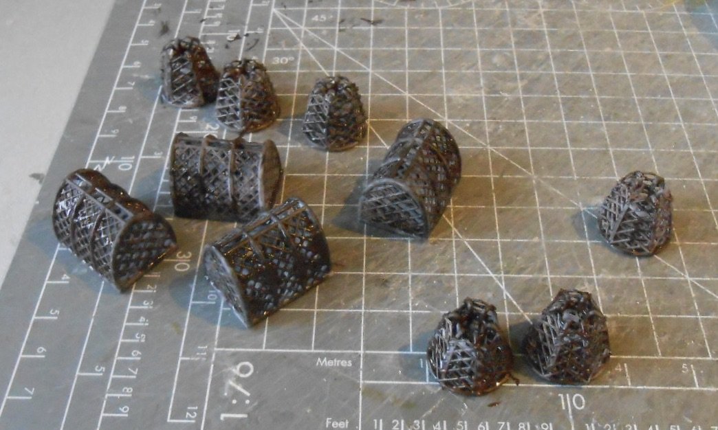
Speaking of bargains, have been looking for some detailing bits and pieces to furnish the quayside. Some more fish boxes from Skytrex have been joined by a dinky set of crab and lobster pots from Scenic 3D.
3D prints, they were less than a tenner [including postage]. Apart from some fancy etching, can't think of a better way to produce such things other than learning lace making & they paint up well too.
-
13
-
 1
1
-
1
-
-
Can't imagine why it would take so long... not sure something this good should be allowed!
What a stunner!
-
1
-
 1
1
-
-
Really useful detailing for something I'd not really looked at, with my track being rail soldered to commercial sleepers. The baseplates wouldn't be hard to fabricate, using microstrip, but the fangbolts really stand out and look tricky to do as individual add ons.
How easy would it be to 3D print them as cosmetic additions (one for each side of the rail)? Northport Quay would need about 500...

-
1
-
1
-
-
Gets a wow from me because know how difficult it can be to produce a line of straight rivets. Have you tried scoring a fine line on the reverse? You can then use it to help alignment - though the clamps and wheels take most of the strain out of things. Rivet transfers are ok, but the GW press is very addictive!
-
1
-
1
-
-
My three thou of an inch calculation was for Paul's 25.3mms gauge widening. Three fifths of five eighths of not very much? Well, as Paul has already said, it can make a difference - even in ordinary fine scale - and S is more than just that. The track on Fintonagh/Swillybegs is 21mm gauge, code 83 rail, with 1mm flangeways in the point crossings. The back to back on the wheels is set to 19.2mm and have found that anything more than 0.1mm out can cause problems.
On 36.75mm, using Code 100 fb rail, it is surprising what you can get away with on plain track with gentle curves - even a full millimetre too wide does not cause derailment! That said, as already documented on Northport Quay, a six foot radius reverse curve certainly caused issues with AJ couplings, something that adding checkrails is yet to fully cure. The P4/S7 folk's quest for true fidelity certainly has merit, but of course comes with other challenges.
As for flat bottom rail fixings, on Belmullet, I briefly experimented with trying to replicate them. First track pins. Way too tedious for me. Same with small bits of microstrip. Ditto. Then tried tiny blobs of pva, which were then painted with rust colour. Another form of torture! The best I could come up with was adding blobs of thick acrylic paint, which gave a hint of texture and an all important variety of colour from both rail and sleepers. There are pictures somewhere on the Belmullet thread and it looks ok.
Why go to all this trouble? When it is not there, the eyes don't really register the omission in the overall scene, but once it is, you suddenly realise that small, extra dimension genuinely enhances things. No plans to do anything to my track at the moment, but these 3D prints look fab, so well done all those who are pushing the boundaries.
-
4
-
1
-
-
As tends to be the case with most things S gauge, it has a very classy look and you are entitled to be chuffed. If I was starting again (and knowing what I know now), S would be very tempting. An elegant combination of big enough, but not needing the space of 7mm scale with no temptation to buy the latest rtr models because there aren't any!
A metric track gauge makes sense, but my nerdy brain just had to look it up in imperial. Answer = three thou short of an inch!
-
2
-
-
Interesting - thanks Angus. Recently splashed out on a new inkjet printer, an Epson one with tanks rather than cartridges. Costs more to buy, but works out better in the long run.
Will have a go with 20 thou sheet, the Alphagraphix card kit sheets could transfer, but are already printed in colour, so that might be interesting. Am thinking the 7mm Narrow Gauge Society drawings would work best as they are just outline.
Learned the lesson of not trusting the scale on drawings early on. It was my first ever attempt at a scratching coach in 4mm (a LSWR brake third). Only after completing it and putting it next to my Terrier did I realise it was too big. Probably about 4.3mm/ft...
-
3
-
-
And there was me thinking my Swillybegs fiction was just nonsense. Clear induction of proposals through Ramelton to Downies and beyond.
-
1
-
-
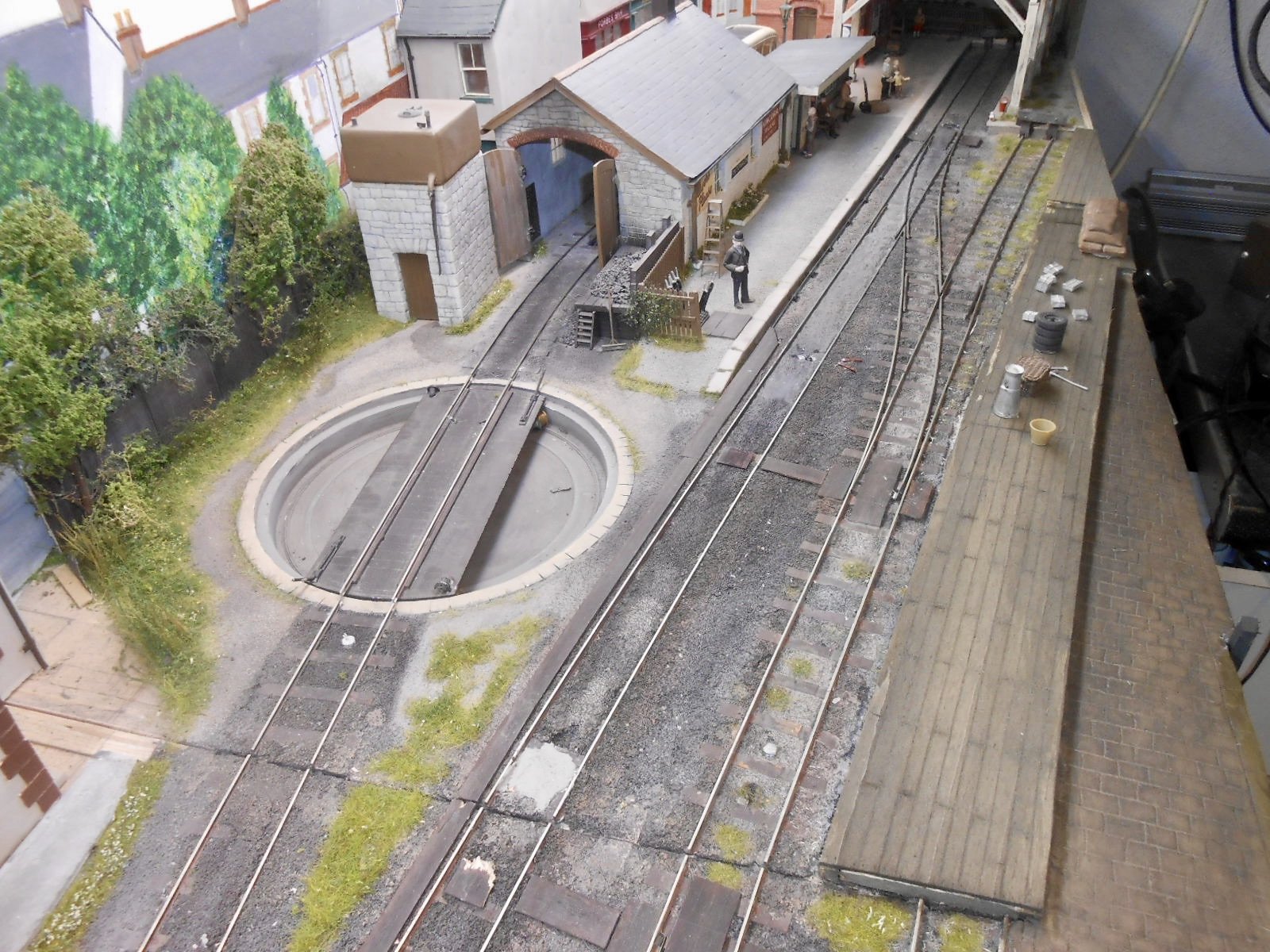
Fintonagh/Swillybegs turntable has similar situation with encroaching foliage! Been meaning to trim it back a little, but have a good excuse not to now.
-
1
-
-
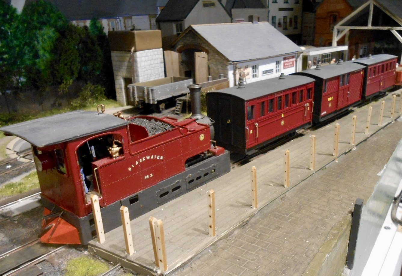
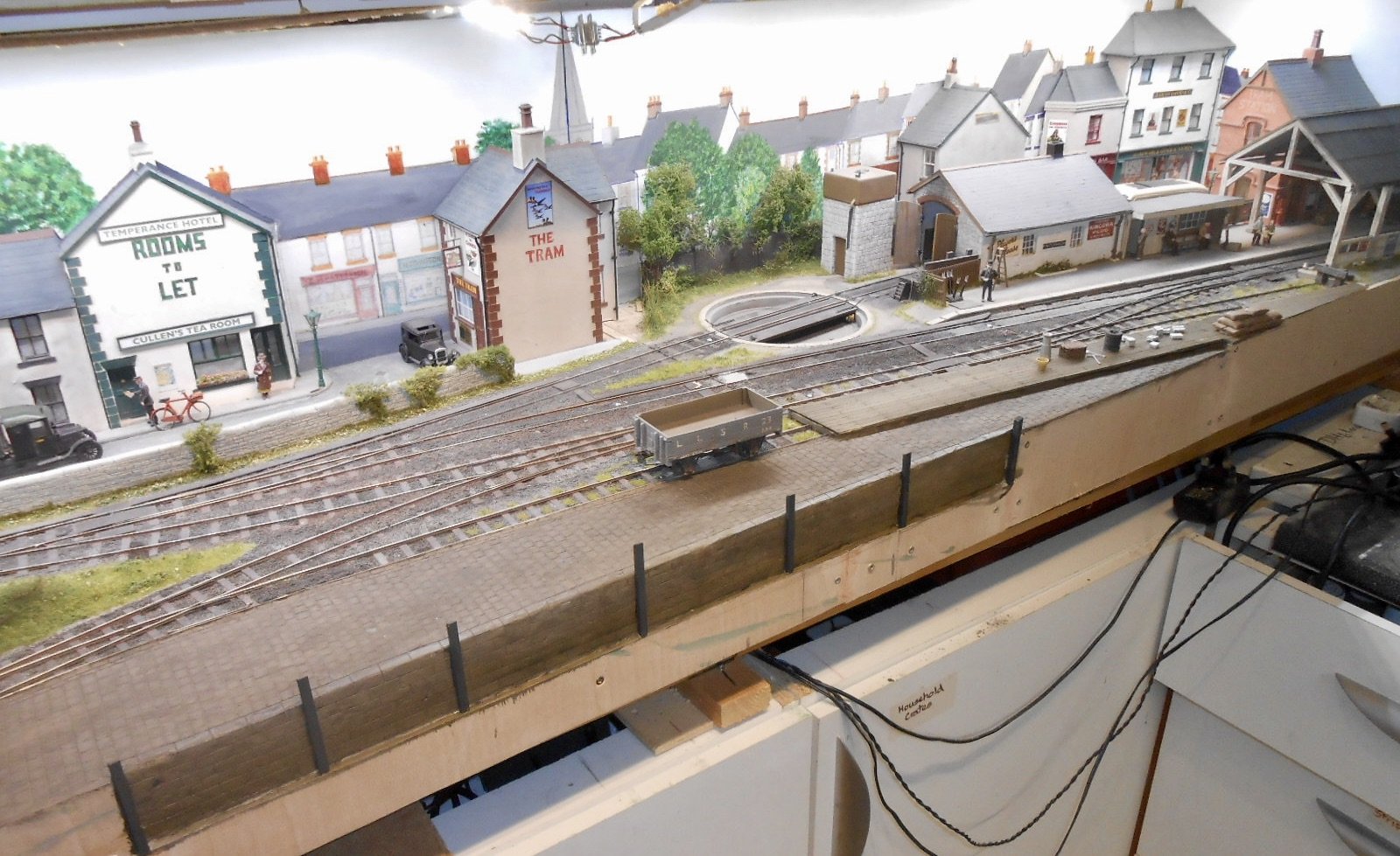
The structural work for the quayside is now largely complete, though much titivation and detailing is still required and orders are going in for some fish boxes [Langley] and some rather nice 3D printed lobster/crab pots I've found on the web. Maybe a couple of figures and some luggage too, while fencing along the back of the tram platform is also needed.
The latter has been made from basswood, scored to represent planking, while more basswood strip has been used to make the large posts protecting the quay wall. Am tempted by the Langley fishing boat, though this would need a baseboard extension to sit on and at nearly £150 ain't cheap, so this is in the maybe file at the moment.
Over Christmas, had to content myself with drawing out some coaches and a wagon on to plastic sheet. We were away at my mother's and it was suggested that taking the soldering iron, solvents etc might not be a good idea. Can't think why...
Anyway, at least now have some basic 'kits' that can be made up when the Muse takes me: two Schull & Skibbereen 4 wheel tram coaches, a Swilly Brake 3rd, also a bogie fish van, plus one of the Donegal red wagons. The latter has already been made up and awaits painting.
-
11
-
1
-
-
Nothing was running when my wife and I passed through Chama, but we had stayed in motel outside Durango and did the trip up to Silverton. Those chime whistles do it for me and the level crossing just outside Durango is as good a place as any to experience the sights and sounds. The loco bell is tolling all the way from the terminus and then the whistling starts on the approach to the main road. The gradient begins here too, so as the loco is opened up it is a delight for all the senses.
There is lots of footage on YouTube of both railways and, like George, spent a happy hour or two watching stuff over Christmas, including the 100 year old rotary snow plough.
-
1
-
-
Didn't realise it was DCC, Leslie. Despite all what is said, seems to me that analogue is simpler...


-
2
-

David's Workbench
in Workbench
Posted
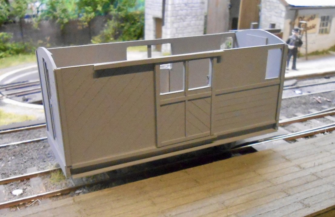
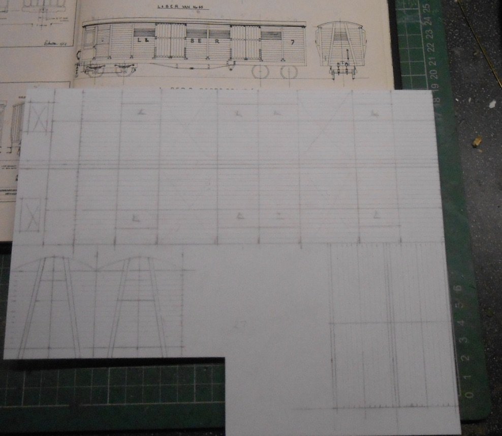
The work I did over Christmas, drawing out coaches and wagons on plastic sheet, ready for assembly has got me on a bit of a roll, so after the three tramway coaches and red wagon now comes a Swilly van. No ordinary four wheeler this time though, it is Bogie No7, which was constructed on a coach chassis.
The drawing, to 4mm scale, and photo come from J C Boyd's lovely album on the Swilly, so the bit over Christmas was to rescale things to 7mm, producing two sides, two ends and four pairs of double doors. I also scribed on the planking and cut out the two windows openings in the guard's door. These are all on 1mm thick/40thou plastic.
On Wednesday afternoon, it only took a couple of hours to assemble these pieces on a floor of 80thou plastic, adding the vertical strapping as I went along from 60x80 thou strip. Recently, I've taken to using Plastic Magic to weld pieces together. For me, it is a nice compromise between rather powerful stuff like Mek and the lighter, but still smelly D-Lemonine. The bottle is less easy to knock over [so far!] and also comes with a handy brush. One downside is that Plastic Magic is quick to evaporate, so you have to work quite quickly, but a strong joint is made in seconds and you get less in the way of finger marks too.
It may not have taken very long to put the main shell together, but detailing is another matter. There is a fair bit of strapping, which also needs riveting, so the GW press has earned its keep again on 20x80 strip.
I always find guard's duckets fiddly things to do & forgot to do a cut out in each side [not for the first time] which will need a bit of remedial work, but they are shaping up ok.
Another potential hurdle is/are the ten louvres [four each side, one each end] which can be a real pain to get looking neat. Tried an internet search in the hope that some enterprising 3D printing whizz had come up with something, but not yet, as far as I can tell. What I did turn up was a short article in MRJ 285, where master modeller Laurie Griffin had used Evergreen 'siding' sheet. In my part of Blighty, Evergreen stuff is getting ever harder to source - and indeed plastic strip generally - but managed to find some on line, so put in an order.
While waiting for it to arrive, I can still be getting on with the bogies and under frame [Alphagraphix castings], while the doors and roof still need doing too. The intention is that the bogie van will be paired with another brake third and provide the train for the Kerr Stuart 4-6-2T when the Worsley etches eventually arrive, while in between there is still the harbour scene to dabble with too.