

David Holman
-
Posts
3,721 -
Joined
-
Last visited
-
Days Won
100
Content Type
Profiles
Forums
Resource Library
Events
Gallery
Blogs
Store
Community Map
Posts posted by David Holman
-
-
Fairly sure the Queens only ran on the Dublin to Cork mainline. Assuming the megafunds, several million euros, were not a problem, then it would all depend on track and bridge capacity, in terms of axle weight, then things like platform clearances and also where turntables of suitable length are available. If any.
However, if enough money available to get the Queen up and running again, it may not be too big a step to ensure there are turntables at Cork and Dublin. That or triangles...
-
 1
1
-
-
Looks 12" to the foot to me!
-
 1
1
-
 1
1
-
 2
2
-
-
It's a hobby, so meant to be enjoyed. Allegedly...
However, still a case of some things being less enjoyable than others. In my case, ballasting, brake gear (all types), painting stonework, to name just three. Half an hour a day generally gets things done, but the adage of a bit of what you fancy doing you good also applies. And why not, when you (and us) can sit back and enjoy another creation?
-
3
-
1
-
-
Plain, simple, but VERY good. Creates a real atmosphere.
A mouse is less less than 3 inches long, with same again for the tail, so in 4mm scale that will be a one millimetre body. No doubt somebody will have done it...
-
4
-
-
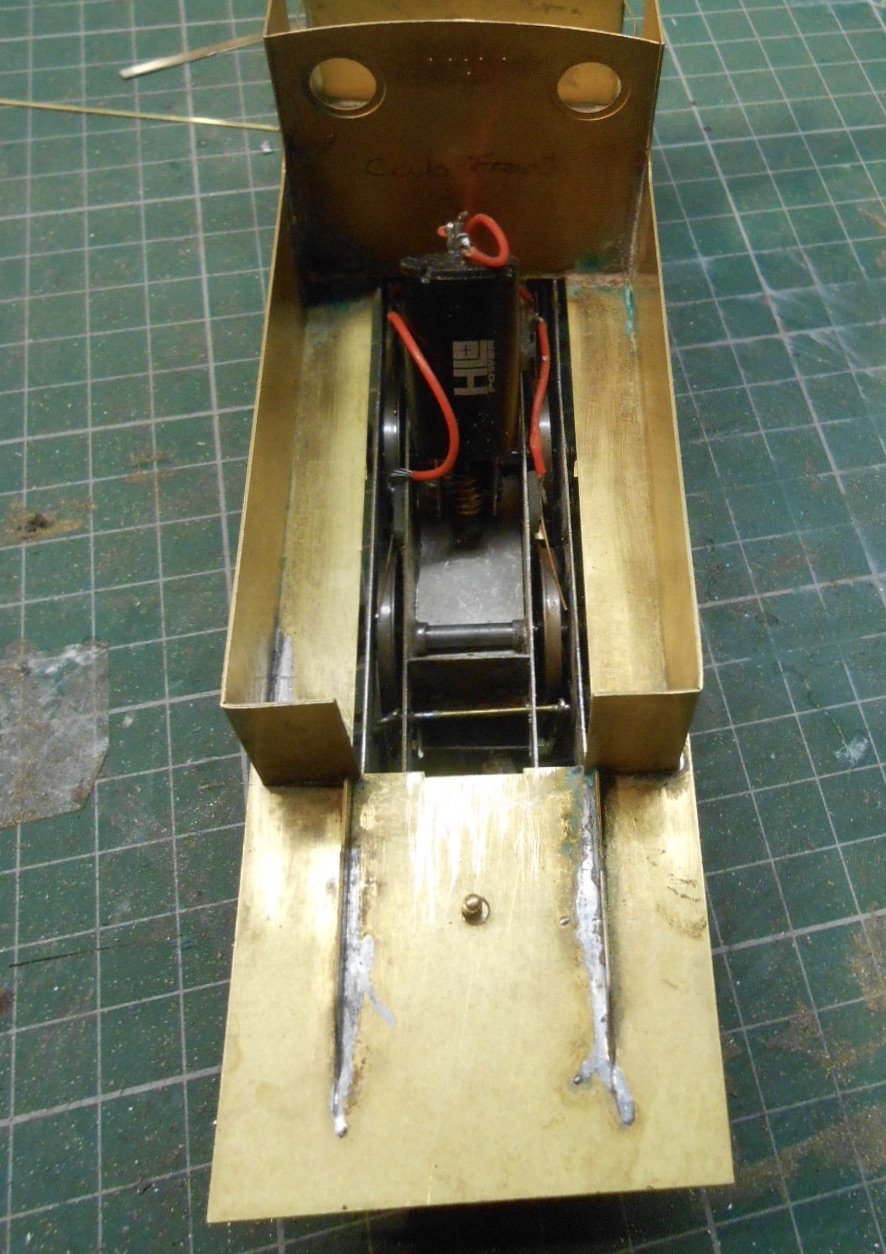
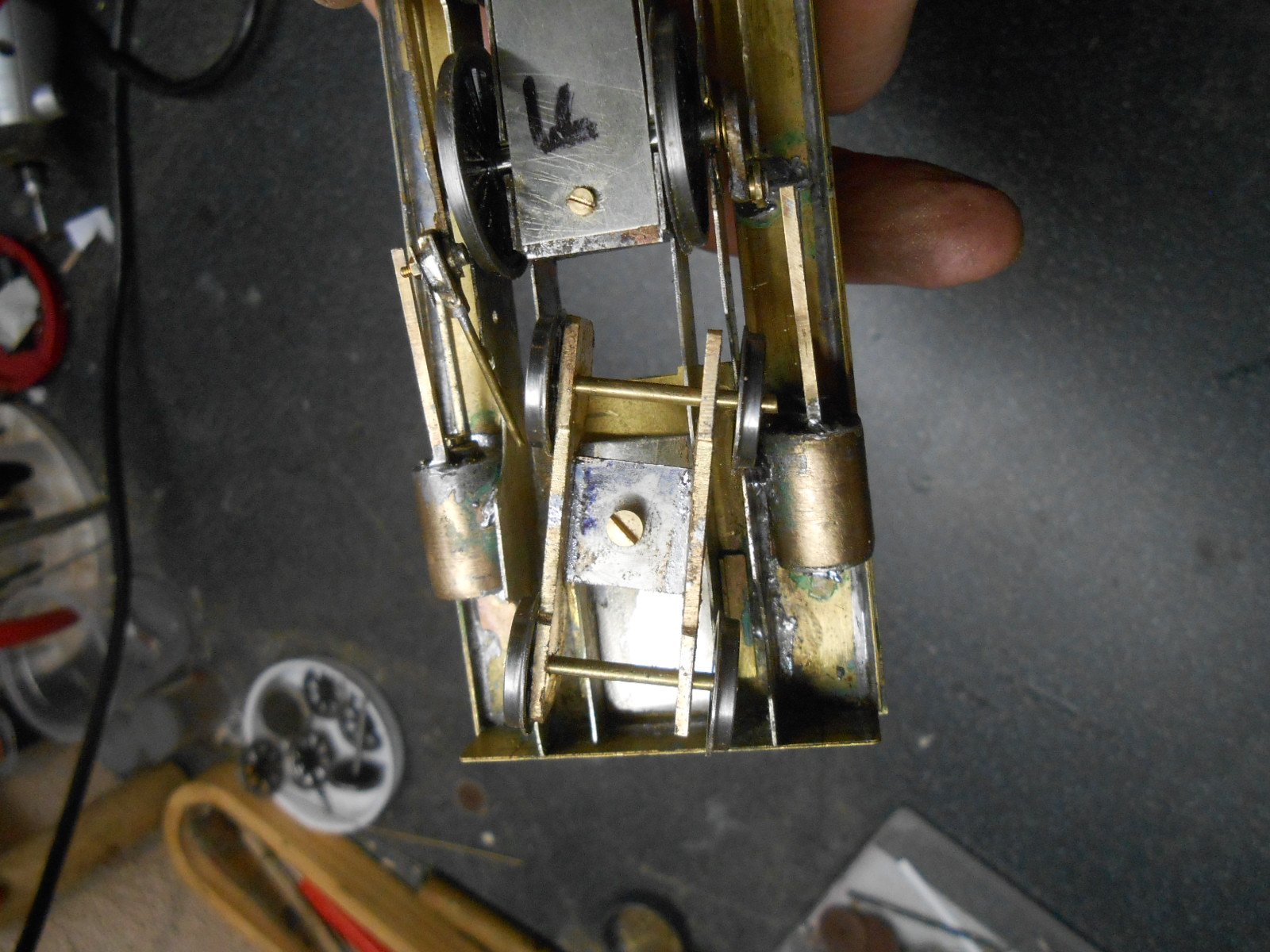
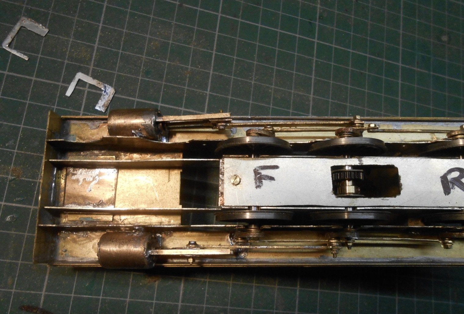
Things get ever more fiddly on the chassis as each new bit gets added. Clearances are becoming very tight!
Having got the chassis rolling nicely, the next job was to add the pick ups. Pretty conventional here, with small pieces of copper clad glued to the inner frames, then phosphor bone wire acting as wipers on the driving wheel treads. Thankfully, the large side tanks and outside frames mean there is no problem hiding all this stuff.

Followed this with the brakes & was tempted to leave them out, but they can be seen poking down behind the outer frames, so needed including. Brass strip was cut and filed to shape for the hangers. The middle and rear pair are soldered to the frames and not connected to the brake rodding. The front pair are also soldered to the frames, but the hangers are hinged here and then at the rear are clipped to the frames so can be swung out of the way if required. Brake blocks are plastic mouldings from Slaters, just glued in place.
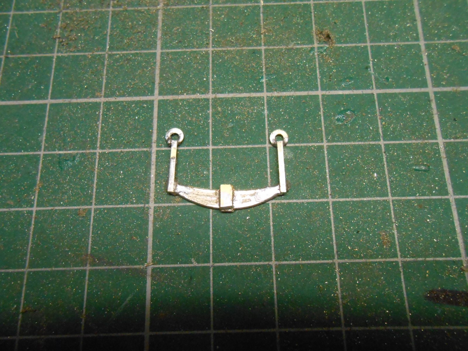
The job that has been causing most stirring of the grey matter has been the main springs under each driving wheel. It is essential that these can be detached, in order to remove the inner chassis for maintenance. Various ideas were sketched out, but in the end I loosely followed prototype practice, as each spring appears to be hung from the outer frames by two brackets.
I had some nickel silver spring 'blanks' left over from a previous kit, so have used these, filing an impression of the leaves into the surface. I then soldered pieces of brass strip each end, to act as the hangers & then added a 12BA washer to the top end. The outer frames were then drilled to take short pieces of 1.2mm brass wire, to which the 12BA washers clip over. Eventually, the springs will be lightly glued in place at one end, but not until I am happy that the chassis is painted and working efficiently, as I don't want to be removing them any more than the bare minimum.
That's it now, until after Christmas, as escaping to the workshop is [probably rightly] frowned upon - though looking at the TV listings I will be needing a lot distractions to avoid catatonic boredom. It would have been nice to get the chassis complete before Christmas, but have learned by hard experience that these things cannot be rushed, as it only ends in tears!
-
7
-
1
-
 8
8
-
-
Tasty!
-
1
-
-
12 hours ago, Metrovik said:
Thanks for all the help and suggestions everybody, just a quick query in relation to the accessories outlet for my controller, is this always active or does the dial have to be turned up in order for it to supply power, the controller in question is a gaugemaster combi. Sorry about all the Questions, but we all have to learn Sometime..... Regards MV
One of the many joys of this forum is how helpful, encouraging and knowledgeable folk are.
-
1
-
3
-
-
You are right, JB. The Airfix is 65 feet diameter, same for SE Finecast. They work out at about 40 feet in 7mm scale...
Kitwood Hill do a variety of sizes. They are American in outline, but easy to adapt and a joy to make. The smallest is a 5 inch 0n2, which works out at about 32 feet in 4mm scale. There is a nine inch one, which will equate to about 55 feet.
Peco do a HOn3 TT which works out at about 50 feet. All that is needed is to make the deck wider, which is simple enough. They cost over £60 though...
-
Turntables are tricky beasts, but by far the cheapest is the old Airfix, now Dapol plastic kit which is still less than a tenner. Frizinghall Models in Leeds do a Meccano based hand cranked kit for about twenty quid, but there is still the problem of getting power to the track on the deck.
The Peco turntable does this for you for about thirty quid or so and may be worth investing in because of that. Next up comes South Eastern Finecast, whose TT is a development of the Airfix one, while the best I've come across are Kitwood Hill Models who do laser cut ply kits for around £75. These need little extra effort and are pretty much complete, whereas all the others require some ingenuity to work properly.
Another option for mounting a TT is to use a standard stereo jackplug and socket as the spindle - you can get the wiring to the track through this. Well worth doing an internet search for other ideas, while my Workshop and layout threads (Arigna Town, Belmullet and Fintonagh) contain posts of my various turntables over the last few years.
As for point motors, the cheapest way is to use servos at less than two quid each, though again, they need a mounting and some way to control them. MERG, the Model Railway Electronic Group have lots of cheap ideas on this. Alternatively, use wire in tube for simplicity.
-
1
-
 1
1
-
-
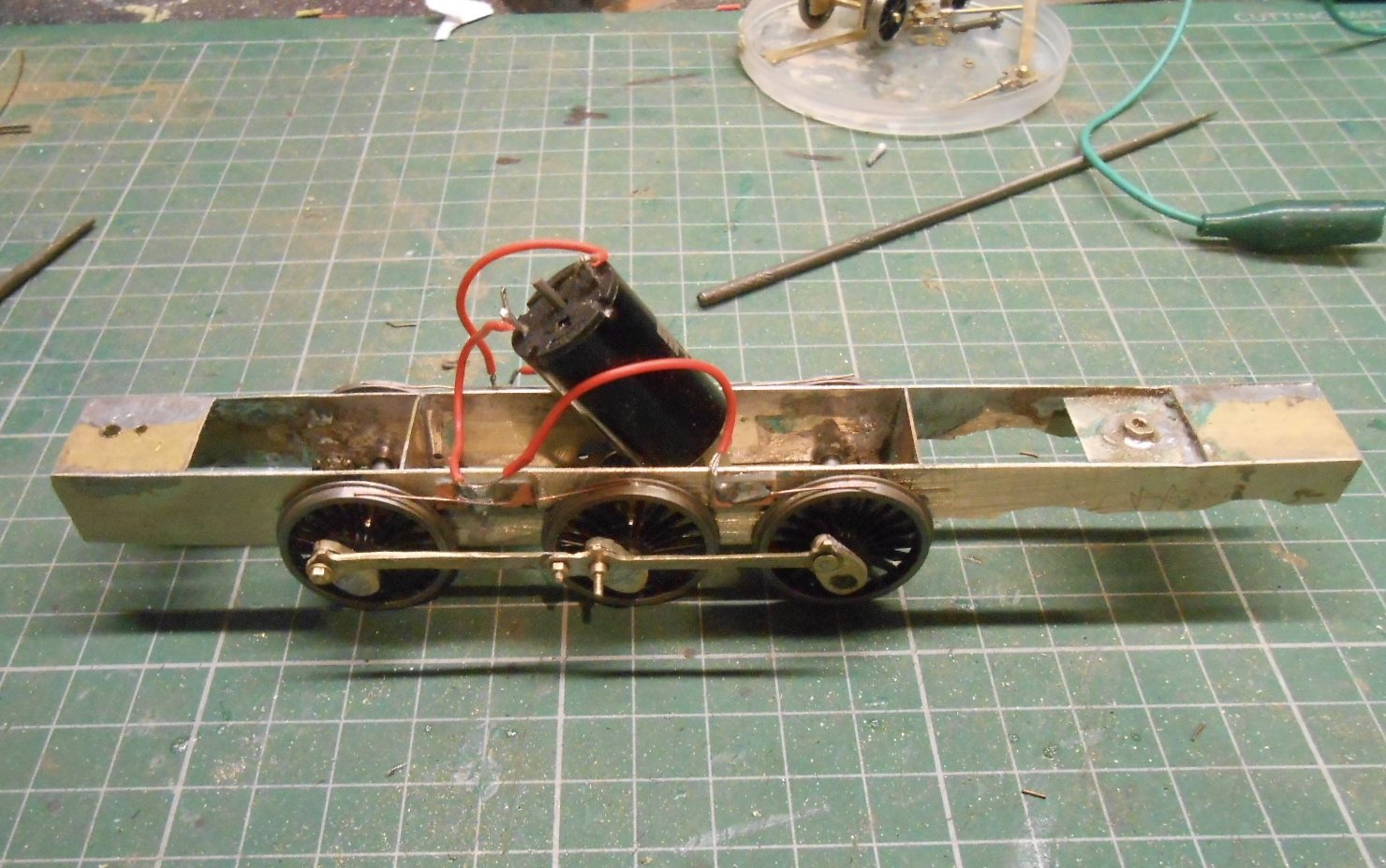
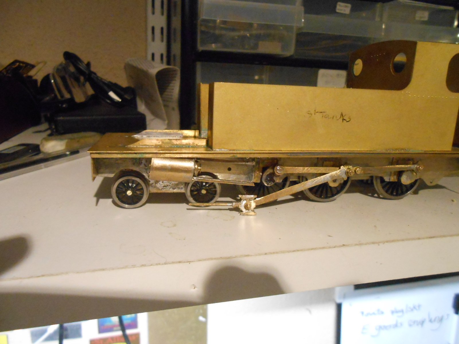
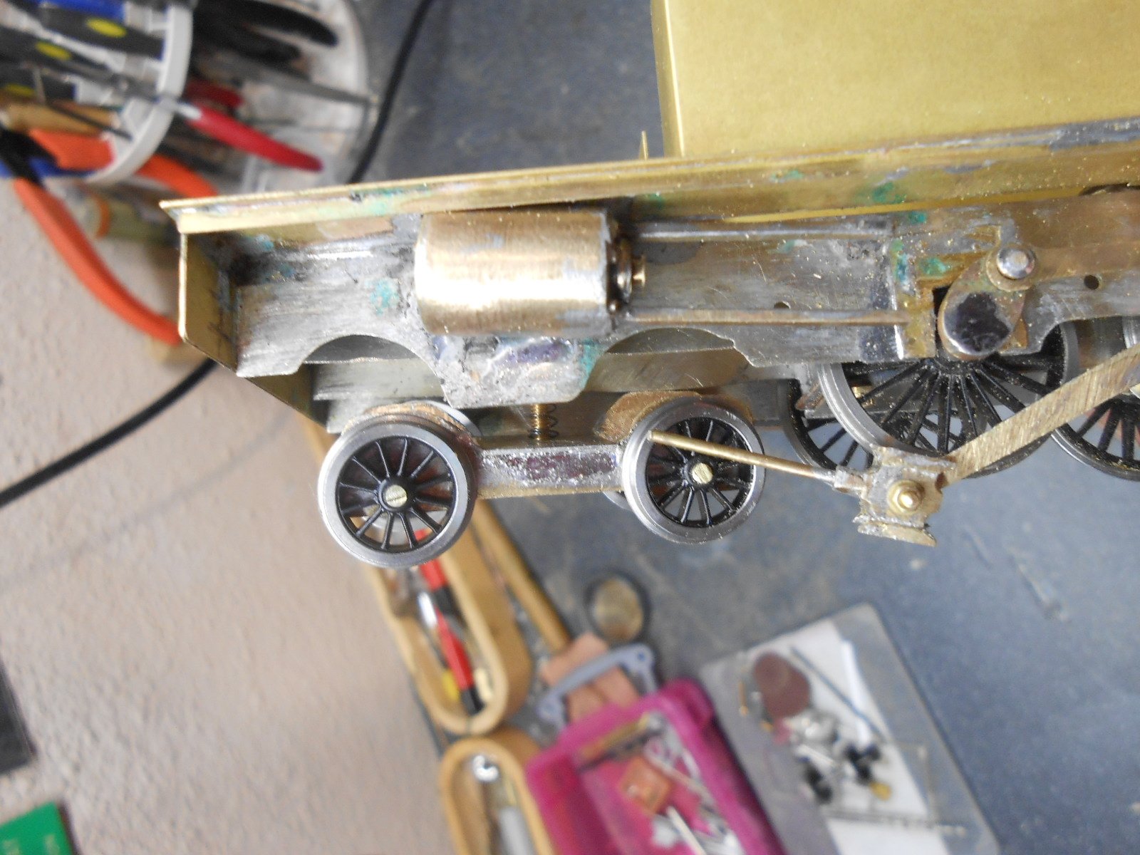
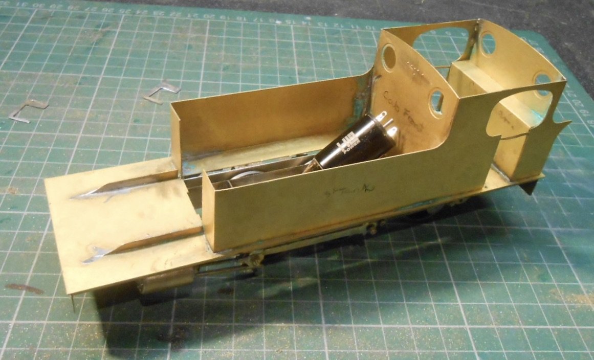
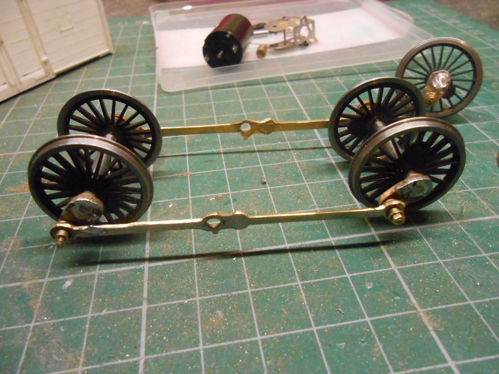
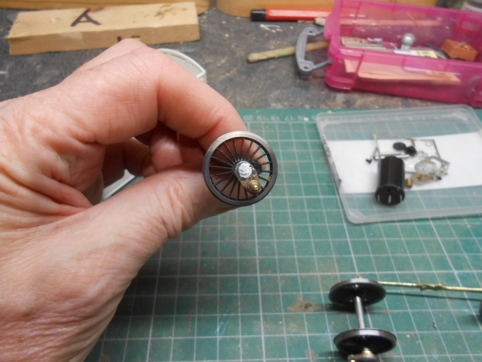
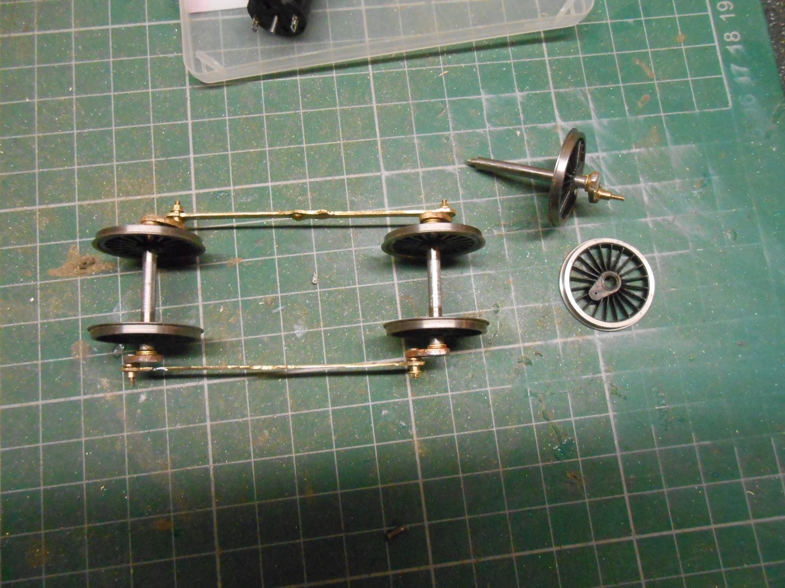
When the lady of the house [She Who Must Be Obeyed], comes in from carol singing in the village square and you excitedly announce you have spent the afternoon making a bogie, it is a tad disappointing to find she is not impressed. Or maybe not...
Anyway, I was pleased.
Nothing too complex, though using 3mm thick brass sheet for the frames took a bit of effort - the reason for this being to add a bit of weight to the unit. Otherwise, it was the usual case of solder the two rectangles of brass together, mark and drill out the 2mm axle holes, cut/file to shape then separate and make a suitable frame spacer from 18thou nickel silver. At the moment, the unit is fixed to the main frames with an 8BA bolt to a captive nut, with a light spring around the bolt, which I hope will be just enough to keep the bogie wheels on the track, without lifting the drivers off it. We'll see... The bogie wheels are Gibson, with slightly too many spokes and 2mm brass wire for the axles, as per Fintonagh.
A few more ticklish problems still to do on the chassis, in terms of pickups, brake gear and especially the underslung springs on the the driving wheels. The issue with the latter is that these need to be removable if I am going to be able to drop the wheels and motor, as a single unit, out of the chassis. Have a couple of ideas, but nothing certain yet other than maybe somehow all attached to longitudinal wires, a bit like the way Mayner does his brake gear.
-
13
-
-
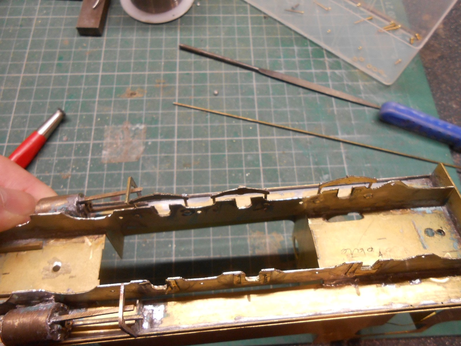
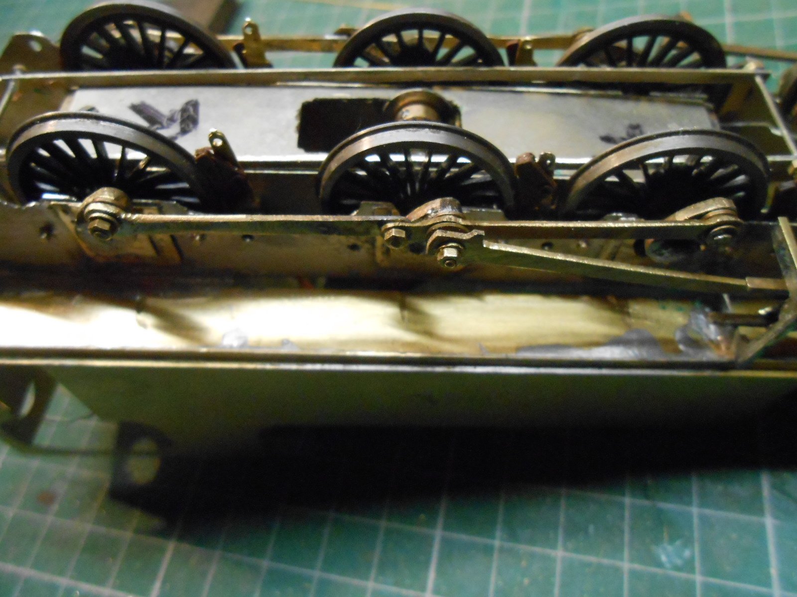
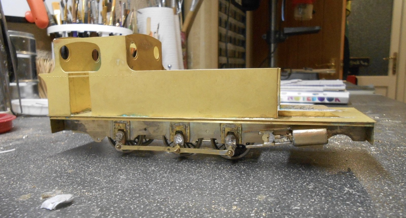
Well, it may not look very different, but believe me the last week has been a catalogue of blood, sweat, tears, singed fingers and a serious pain in the primary orifice!
Prime among the problems was my own carelessness. In removing one of the cranks to fit the new motor, I managed to partially melt one of the driving wheels. Yes, really... A bit of tweaking and some superglue seems to have restored order and this is how the cranks are fixed now. I learn, eventually.
However, this is getting ahead of things, because despite my best efforts, I must have spent two days trying to just get the basic chassis to roll freely. Unlike a simple 0-6-0, there really are a shedload of variables in an outside frame chassis & at one stage I was contemplating making another new one, or even throwing it all in the bin. However, a two day break in France [Arras Christmas Market] was just what was needed & suitably refreshed [with a full wine rack as well] I stripped the chassis down and reassembled it using my Poppy's Woodtech jig. Turns out things were not quite as square as I thought.
While rebuilding, I made sure all the bearings, cranks and so on were nice and snug, because the initial slack was also causing problems. I then took my time building the new gearbox, reaming out its bearings and cleaning the loco axles so everything was nice and smooth. And hey presto, it all worked. There was also a lot of slop in the keeper plate, so that is now tighter too. Fingers crossed, I will not be removing the wheels again any time soon. Being hidden away, I'm not even going to paint the inner chassis.
Another job was making the coupling rods jointed & this made quartering the wheels easier as I could do a pair of axles at a time. So, it was at last possible to start some new work. Only two new parts - the coupling rods - but to say fitting them was a fiddle is more than a bit of an understatement, though it pretty much sums up the project thus far. Nowhere near enough fingers!
Considerable care is needed on any loco with outside cylinders. There are clearances to check all over the place and some of them are fag paper thin. At least there is plenty of room behind the crossheads, but very little between the con rods and coupling rods, while the cranks also want to clout the slidebars. The cylinders are angled too...
However, eventually all seems to have gone well and the outside motion appears to work nicely. The connecting rods take all the slop from the centre crank pins, while at the crosshead, there is just a 12BA nut and bolt. The motion bracket still needs work though, but it really was a case of stop while I was winning.
The moral of this project is at the extreme end of measure twice, cut once. I've been working it out as I've gone along, but it's caught me out at every stage, so really must write up an abridged version of these notes for future reference.
-
9
-
2
-
-
Lovely combination, Leslie.
-
2
-
-
Splendid.
-
1
-
-
No problem, Derek. After all, I only copied something else! There is something quite therapeutic about working with DAS and certainly more interesting than ballasting. Both definitely worth it in the end and just things we have to grin/grimace and get through.
-
1
-
1
-
-
Very subtle, but it just looks right with at heavy load on.
-
2
-
-
Fine models, neat weathering and do I detect a lovely prototypical slight sag in the middle of the bogie? Certainly works for me.
-
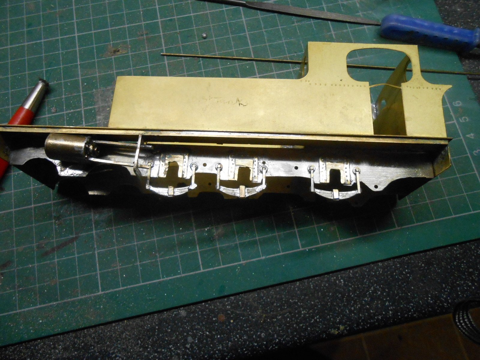
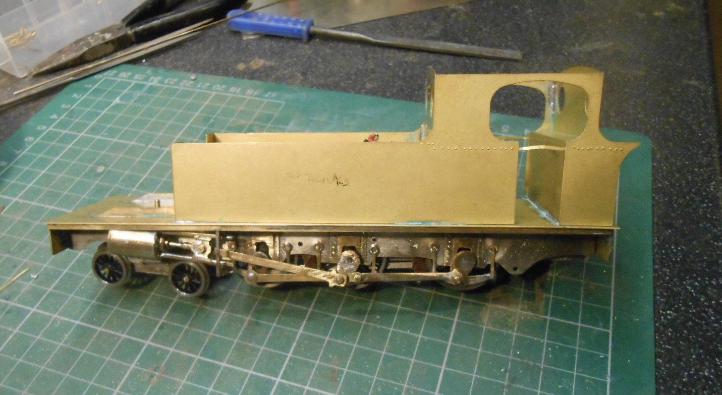
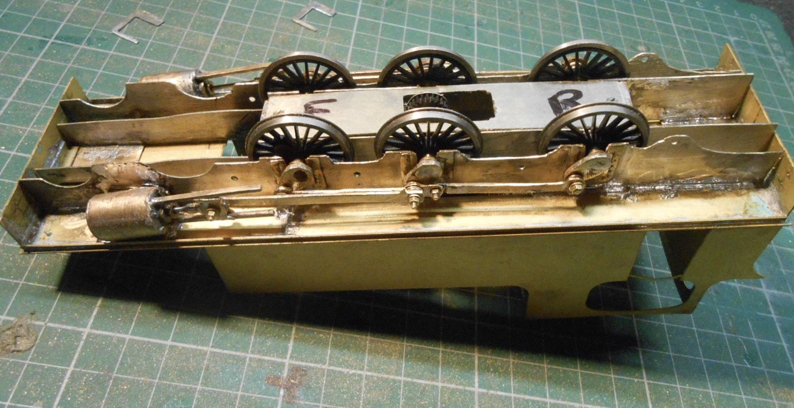
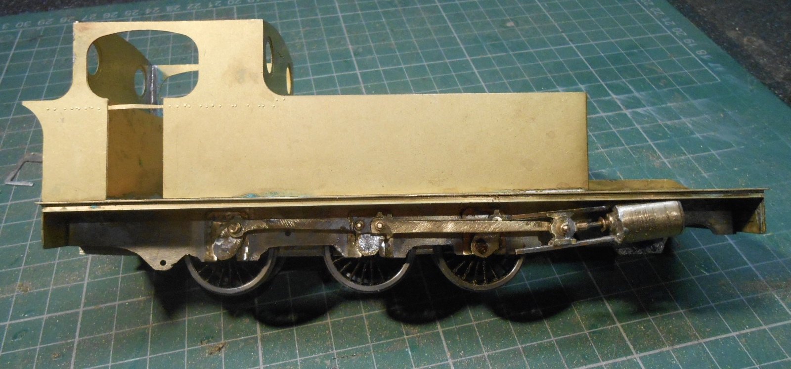
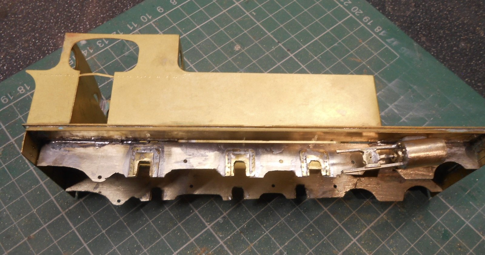
While waiting for a new gearbox to arrive, have been working on other aspects of the chassis. First up was to fit dummy hornblocks to the outside frames. Two rectangles of 10 thou brass sheet, cut out with strong scissors, soldered together, then soldered to the frames. After, made cut outs for the extended axles with a slitting disc in the Dremel. Nice and easy, for once.
A bigger job, especially with the number of parts required, was the outside cylinders and motion. Remembering the Horlicks I made earlier as a result of diving in without enough thought, I read up a bit first. There are several options, including making the ends & then adding a wrapper, but decided to get out my mini lathe and turn down a piece of brass rod to the right diameter, drill out the centre & then add the various details
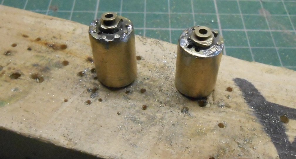
Started with the ends, which are simply pieces of 18thou brass sheet, soldering in place then filed to shape. Thinking ahead [for a change], I used 240 degree solder for this, so I could use 145 for adding later pieces. The cylinder ends are bolted to the casing and a quick experiment showed that my rivet press would not make large enough indentations, so instead I drilled 32 one millimetre holes [eight bolts each end] and then soldered 1mm brass wire into these for the bolts.
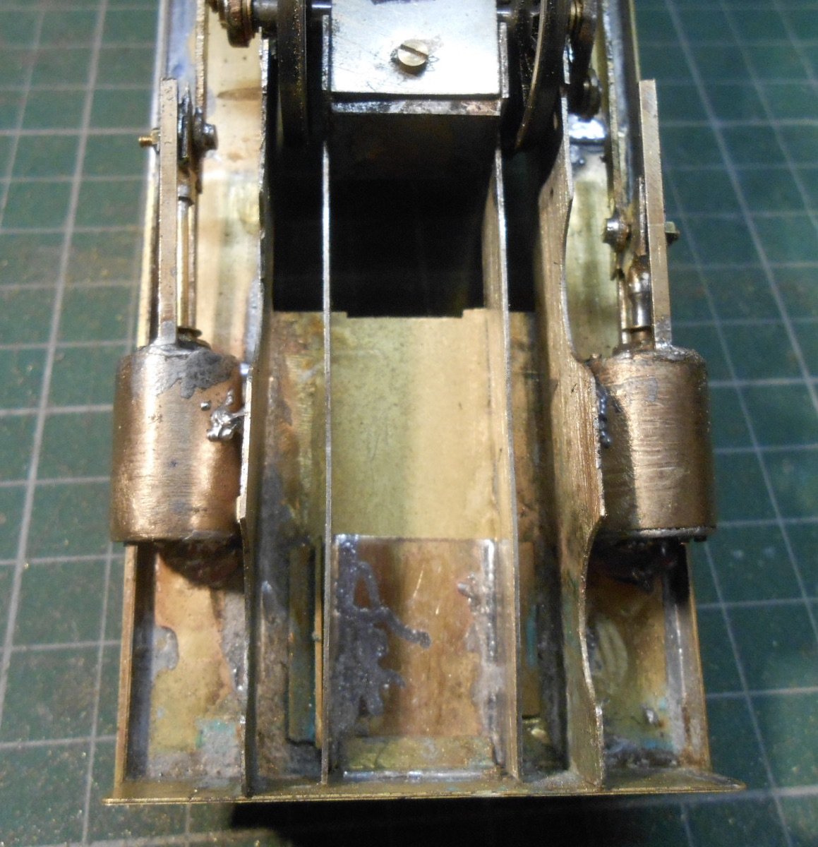
Inspiration for the next bits came from Tullygrainy's Workbench thread & I started looking through various boxes of bits for stuff to make the gland where the piston rod goes into the cylinder, plus the slide bars and crossheads. The piston rod gland is made of three washers, soldered together, with a 7mm scale wagon bearing, drilled out for the rod to go through. More tidying up still needed, but the results are shown below:
Ideally, the slide bars should have been brass strip, but nobody seems to sell the stuff other than online & it is expensive enough as it is, without adding the postage. Looking through the rack in my local model shop [any amount of tube, wire and rod, but no fine strip], realised that 1 x 1.5mm U section channel might do the job. It worked out quite well, because I soldered pieces of 1mm brass wire into the channel & then used the latter to fit into holes drilled into the cylinder ends. Used 145 solder again and had the cylinder clamped into the bench vice to act as a heat sink and stop my hard work coming undone.
Making the crossheads was similarly fiddly. At the core is two rectangles of 28thou brass soldered together & drilled through for the connecting rod. The piston rod is a piece of 1.2mm brass wire soldered into a crankpin bearing, which was in turn soldered the brass rectangles. 240 solder to begin with, then 145 again after that. Each crosshead then needed 4 small pieces of brass strip soldered top and bottom to make the flanges which run in the slide bars. Happily, nothing fell apart while I was doing this and, following a bit of tidying up, the crossheads are a nice easy fit in the slidebars.
The last two pictures show the dummy frames and the cylinder units held in place with Blutak. So, progress at last - for now, anyway!
-
14
-
4
-
-
Sorry Angus, 90 is fine, 45 not quite. Must be the way I tell it! Fingers crossed, sorted now, though am sure there are other things yet to bite me...
-
Few things are more tedious than ballasting!
-
1
-
-
Many thanks, Ken, much appreciated. Have ordered a basic Roadrunner as a replacement - the first one was a Roadrunner+, with the extension cradle and 60:1 gears, so have gone for 45:1 this time, to keep things simpler.
However, fear you are right, as I did indeed file those pips off before I read the instructions! Lesson learned!I
There is no doubting the quality of HL stuff, though to me fixing the worm to the motor with cyano seems odd. In 7mm scale it is always a grub screw. Speaking of which, the self same to fix the final drive gear to the axle is definitely an accident waiting to happen. Thought I'd lost mine, but fortunately it had attached itself to the motor.
-
1
-
2
-
-
That sounds familiar, Alan. I wondered if I'd got a bit of superglue in the gears, but couldn't find anything. The HL gear boxes seem very good, but from years of 7mm working, where you usually get stuff ready assembled, boy are they fiddly, to me anyway.
Very much making it all up as I go along and as I mentioned in the Questions thread, don't have a definitive guide to follow, so will create one for future reference. Hopefully there will be a Swilly 4-6-2 and Donegal 4-6-0 to follow.
Jointed rods being worked on at the moment and coupling rods to follow, then cylinders, crossheads, slidebars and dummy axles boxes, before the front bogie unit. I've built an entire loco in less time that this chassis!
-
5
-
-
Two steps forward, but one back at the moment - plus sore fingers too.
Many thanks to those who helped with ideas re quartering the cranks. I used the old John Ahern book to make a simple jig so the six crank pins all have the same throw, then it was a case of filing and grinding the initial 2mm brass rectangles to shape. One hole is 1.7mm diameter, to go over the end of the Slater's wagon axles, the other is 1.2mm to take a 12BA bolt, fitted from the rear, soldered and then the head filed flat. Slater's crank pin bearing then go through the coupling rods and are held in place with 12BA nuts and washers.
So far, so good.
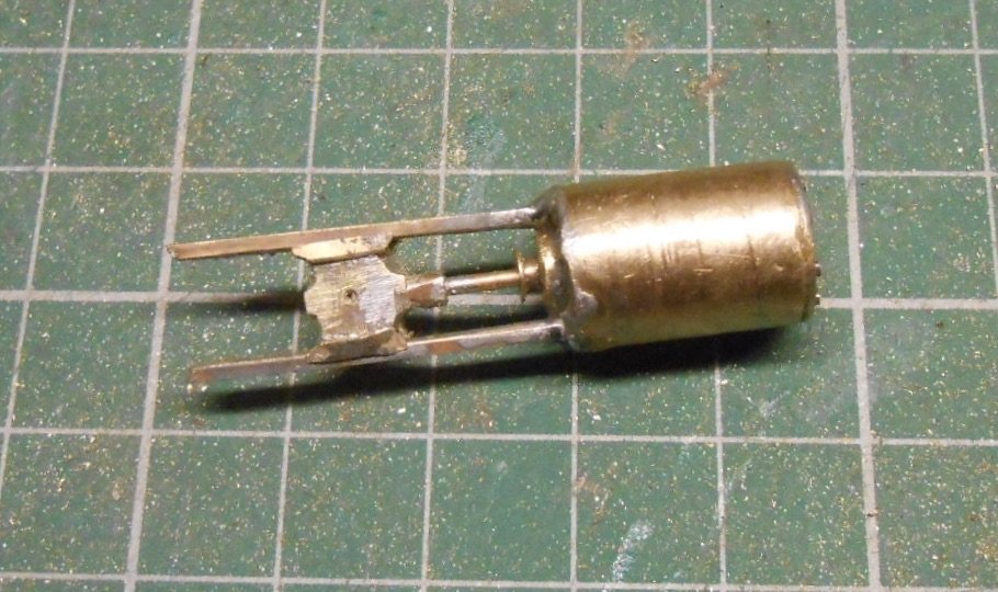
The arrival of a High Level motor-gearbox meant that, once this was assembled, I then had to take one of the centre drivers off its axle, so the gearbox could go between the frames. Those who read my post in the question section will know I had managed to quarter the cranks successfully enough, but more at 45 degrees than 90, so on refitting the cranks I quickly fixed problem and was ready to test the motor in the chassis.
Unfortunately, here was where the problems started. Again.
The motor gearbox seemed to work well enough on the bench, but fitted to the chassis it was decidedly clunky. At first I thought it was the quartering that was out [though the chassis rolled nicely on its own], but eventually it became clear that something in the box wasn't right. Indeed, it looked like the top gear, working from the worm was trying hard to strip its nylon teeth against the brass. Whatever, I now need to order a new 'box, because in dismantling it for further examination, said gear pinged off into the far, darkest reaches of the workshop & has run away to join the circus.
So, while waiting for a new box to arrive, have started making parts to create jointed coupling rods in the hope that I will eventually be able to add a degree of springing to the chassis.
One day.
Eventually.
-
9
-
-
Excellent stuff John and some very useful tips too.
-
2
-
-
Don't need one for 7mm scale HT, as Slater's axles and wheels have square ends which takes care of the problem. Not sure a jig would help with outside cranks, so used the old school method of simply setting the first pair as the datum, then added the second pair, with the rods, quartered these as an 0-4-0, before adding the third pair of cranks and doing the same. Had got it all running nicely when I noticed one crank wasn't pushed in far enough and in correcting that bollixed the whole thing up, breaking a golden rule of stopping for a break beforehand. The cranks are soldered to the axles, by the way.
The cranks are home made from 2mm brass strip, drilled in a jig for the axle ends and crank pins. Have used the Slater's set up for the latter, with 12BA bolts soldered in for the pin and top hat bearings on the coupling rods so pins can be fixed with nuts and washers. By leaving the bearings off, there is enough slop to quarter the wheels in pairs.
However, my High Level motor gear box has now arrived, so I"m going to need to remove the centre axle to fit it, so might as well move it all to 90 degrees anyway. Am also thinking that that, with the keeper plate giving me a small amount of vertical movement, I might as well make the coupling rods jointed and fit a bit of springing to the outer axles.
One of the problems of scratchbuilding is the lack of instructions and because I haven't built a loco for a couple of years, it is all to easy to forget some of the conventions. With at least two more outside framed locos to build, I must write myself an aide memoir for future reference, once I've got this one working properly!
Hopefully a report and pictures soon.
-
3
-

Clogherhead - A GNR(I) Seaside Terminus
in Irish Model Layouts
Posted
At least it rhymes!
One definition of sophistication is, when listening to the William Tell Overture, you actually think of the Lone Ranger. I know my place...