Horsetan
-
Posts
2,682 -
Joined
-
Last visited
-
Days Won
4
Content Type
Profiles
Forums
Events
Gallery
Blogs
Everything posted by Horsetan
-
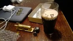
I hope that's not blue asbestos
-
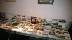
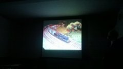
Thing is, these scenes are all within living memory....especially the 1970s ones. If you're doing period modelling, photos like these are priceless.
-
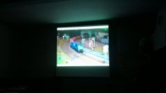
That really is quite something.
-
The ones I looked at appeared to be very black. As black as a priest's socks (which should be really black, and not actually just a very very very very very very very very very very dark blue).
-
Album updated
-
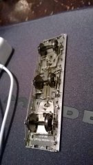
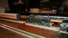
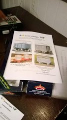
Richard's etched carriage body to go on top of the LRM Cleminson underframe
Horsetan posted a gallery image in Member Albums
-
-
-
-
-
Apparently Leslie's other hat is Provincial Wagons. I didn't know this!
Horsetan posted a gallery image in Member Albums
-
-
-
-
-
-
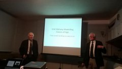
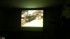
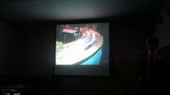
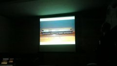
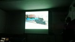
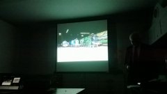
Stumbled across a huuuuuuge collection of colour photos on Flickr, posted by the intriguingly-named "MajorCalloway". Amongst them are a small, but significant number of railway photos, including a gloomy platform shot inside Kingsbridge Station, circa 1961. Also this one at Dun Laoghaire. They are mostly from the 1960s and 1970s, but there are some late '50s pics in there as well. Click here to view the album Kindly note that I accept no responsibility for wallowing in nostalgia
-
Now all it needs is the Irish talent for improvisation.....
-
-
Wanted - Great Northern Irish Railway Pictorial by Tom Ferris
Horsetan replied to Warbonnet's topic in For Sale or Wanted
There was a copy of this for sale at the IRRS meeting last night, oddly enough. -
-
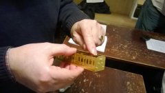
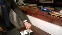
Etched kits by Terry McDermott (later Studio Scale Models)
Horsetan posted a gallery image in Member Albums
-
-