.png.c363cdf5c3fb7955cd92a55eb6dbbae0.png)


lucas
-
Posts
57 -
Joined
-
Last visited
-
Days Won
1
Content Type
Profiles
Forums
Events
Gallery
Blogs
Everything posted by lucas
-
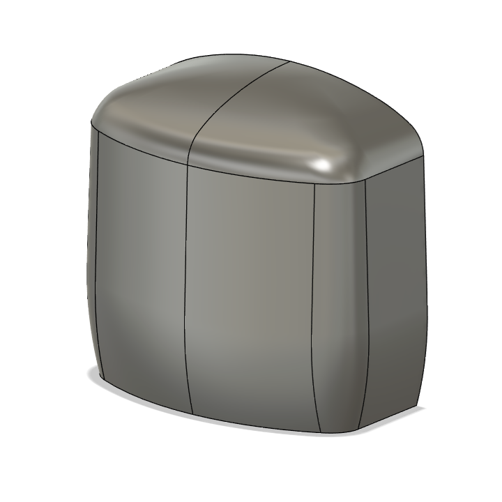
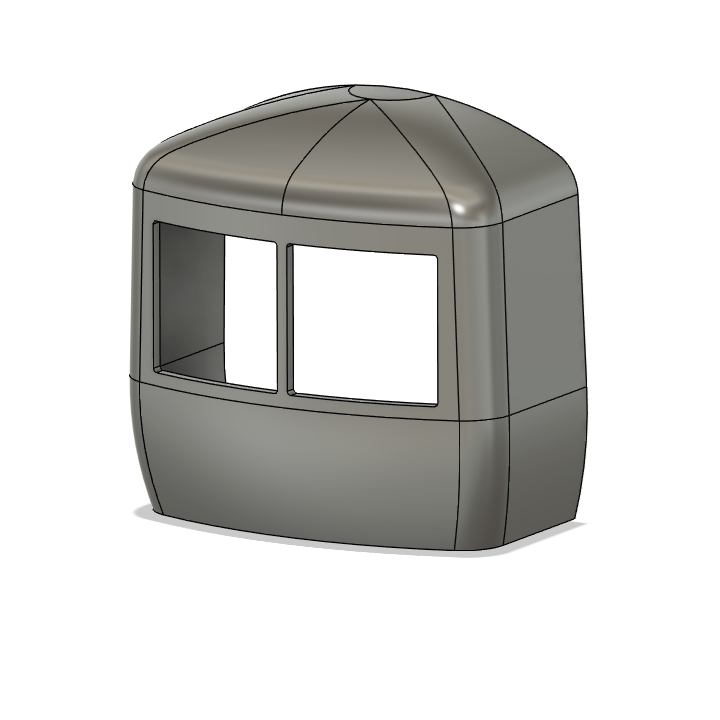
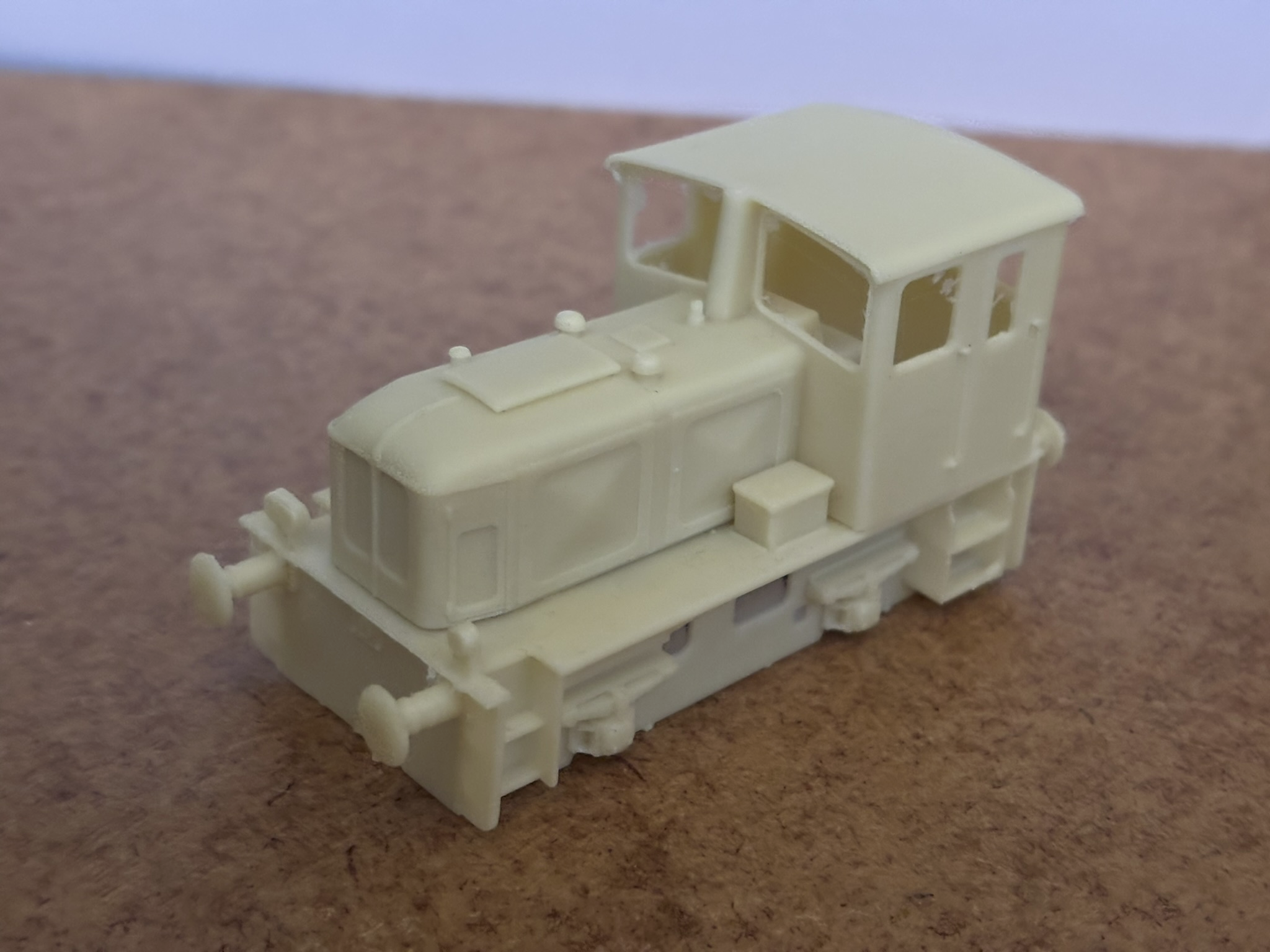
Apologies for the lack of updates on the cab, I have been mostly busy preparing to move house shortly. But I have managed to find a bit of time to improve the model of the cab. Here's my current iteration, void of any detail, showing the curvature: It's still not perfect, but it is definitely an improvement over my previous attempt. This picture of the framework shared by @Mol_PMB actually helped a lot in understanding how the curves were formed on the prototype: The curvature matches the drawings as close as I can get, but I'm not sure how accurate the drawings actually are in this regard. I'll start adding some basic details like the buffer beam, wind shield, and headlights and see how it looks then.

-
There were 5 between 1879 and 1893. The C&BR had Albert Quay. C&MDR opened their own terminus at Capwell in 1879. Previously they had also used Albert Quay, but they closed their link with C&BR after building their own station. GS&WR had Penrose Quay and C&YR had Summerhill. After purchasing the C&YR, the GS&WR built a new 'combined' Glanmire Road (now Kent) which opened in 1893, replacing the two previous stations. The fifth was the CB&PR's Albert Road station. It was still using 5'3 until 1900 when it completed its conversion to 3' gauge.
-
At least 22 still retains the drive box on the outer axles, but only the inner drive box is actually connected. According to the description of this photo on Flickr: This modification had presumably already been made by the time the Irish railcars were built, which explains why they only had one driven axle per bogie from the factory.
-
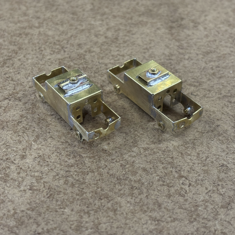
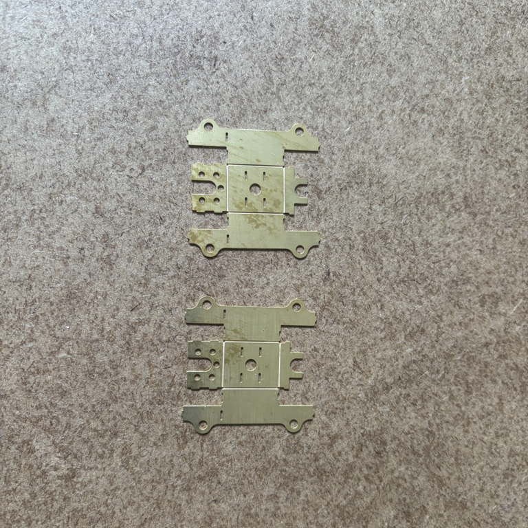
I was mostly thinking of the unintended seams where brass and 3D printed parts join, but I guess it's nothing that a bit of model filler can't fix. Also, moving the discussion about motor bogies here: The High Level LongRider would've been ideal with 40 mm wheelbase, it's a shame it's not made any more. I am in the process of making my own etched motorbogies for my C class build. They're designed around a Mitsumi motor with a 30:1 gear ratio (the largest gear ratio I could find for a single stage worm) which should give a nice slow top speed of ~50 scale mph. I had already built the first set, but I miscalculated the clearance so the gears bind up pretty badly. I need to get them remade with a bit more clearance. I have attached some pictures below. Some of my thoughts: My design only works for 21mm, it's too wide for OO gauge. You would either need to have a design where the motor isn't contained within the side frames, or a teeny tiny motor. High Level discontinued the LoRider/LongRider when their supply of Mashima motors ran out. There aren't many sources of good dual-shaft motors anymore which are required for motorbogies like these. I'm using Mitsumi motors I bought in bulk from China for cheap, but there are definitely a few duds in my batch. I spent half an afternoon testing and measuring all my motors to make sure the ones I'm using are good and well matched, but not everyone has the equipment to do that. And I have no idea about their longevity. As far as I know Black Beetles use Mashima motors too (or at least did in the past) so if you're planning to use them it might be worth checking if they have enough supply available. Motorbogies aren't very powerful, so for a railcar with 2 intermediate coaches you would probably need at least 2 of them. But it might be worth doing some testing through tight curves or an incline.
-
I agree that etched kits always look a lot better for coach/railcar sides. A hybrid etched/3D printed kit would be my preference too. Not sure what you want to do with the roof? The front section above the cab would need to be 3D printed. The rest could be brass but it might be tricky to get the curve to match up perfectly. We could also print it and get the curve exactly the same, but that would probably have to be printed in a few sections giving a few more joins to clean up.
-

"Voiding the Warranty" - Mol's experiments in 21mm gauge
lucas replied to Mol_PMB's topic in Irish Models
Absolutely. I was mostly just eyeballing it so having some proper cross sections would be a big help -
"Voiding the Warranty" - Mol's experiments in 21mm gauge
lucas replied to Mol_PMB's topic in Irish Models
I had actually thought of doing something similar. I'm sure you're a lot more experienced with etch design than I am, but I'm happy to help with the CAD/3D printing. I had started messing around in CAD some months ago to try and get the cab shape right, but haven't worked on it in a while now. Below is as far as I'd gotten. It doesn't have any real detail, and the shape still looks a little off to me.
-
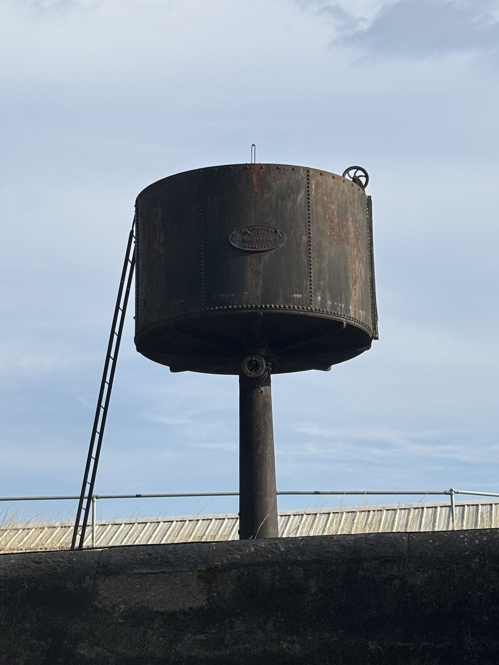
There's one still standing in the far corner of Kent station in Cork. Picture taken from the Lower Glanmire Road earlier today. Had I been 30 seconds earlier with the camera you would've seen 2601/02 pass by in the background.
-
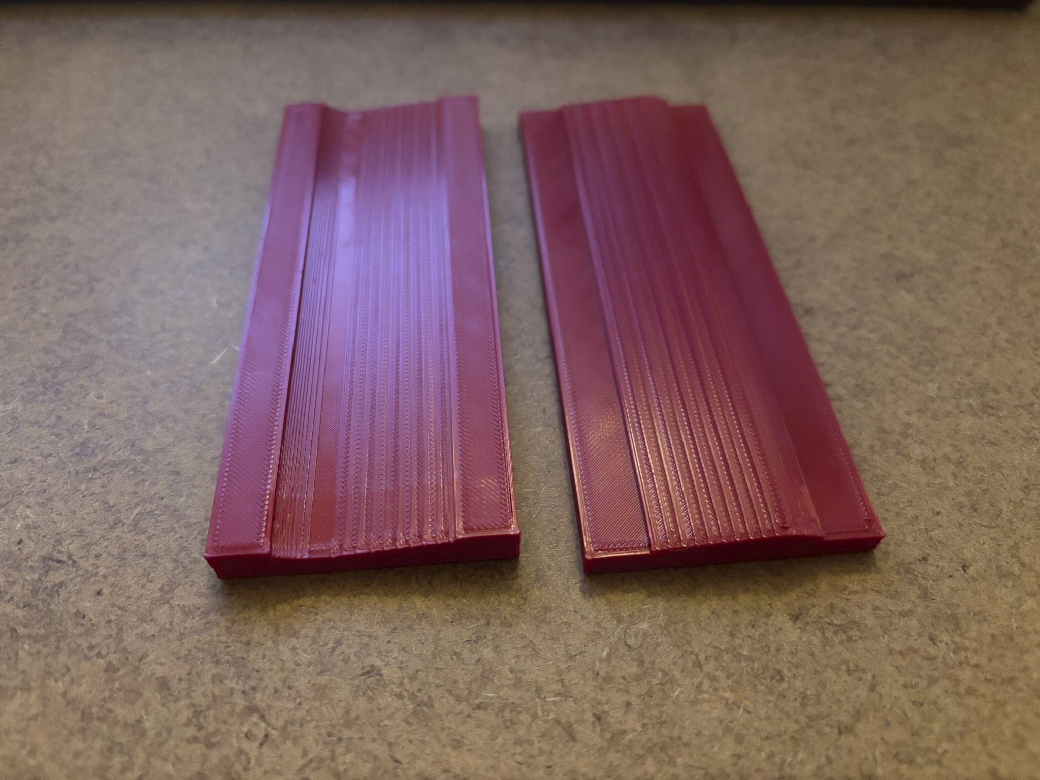
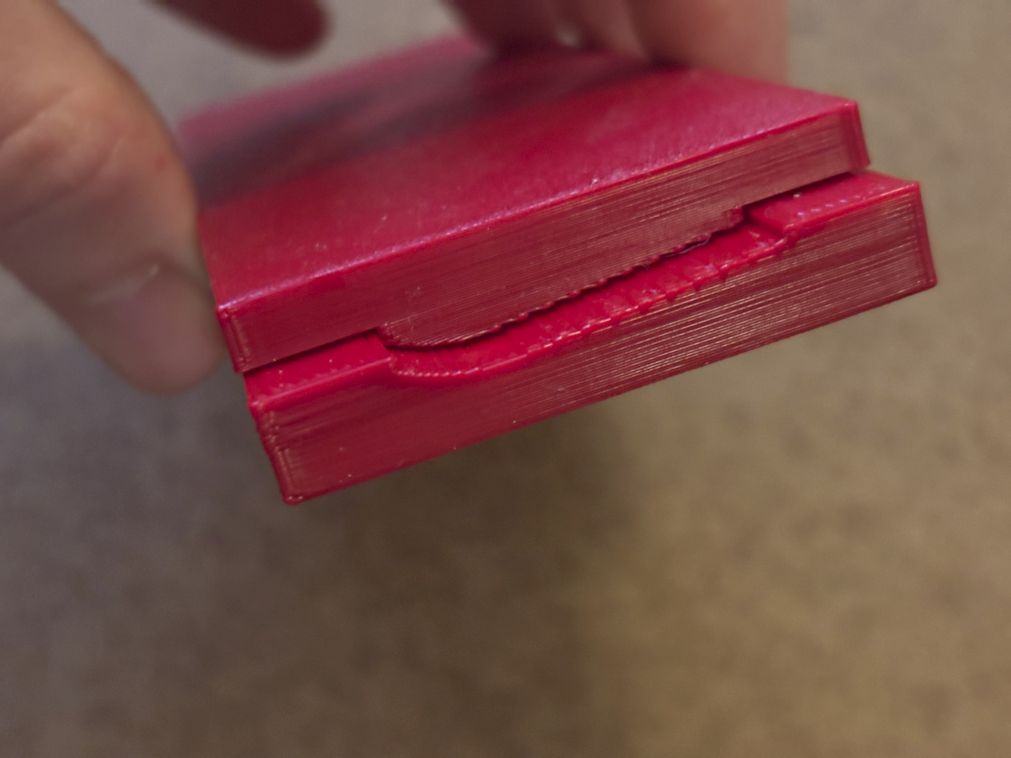
I have used 3D printed dies in the past to get the curve in coach body sides consistent. These are printed on a very coarse setting on my printer since the surface doesn't matter anyway. The brass etch is sandwiched in between and pressed tight in the vise. It takes a little bit of trial and error to get the die right since brass tends to 'spring back' a little bit, so the die is designed to have a slightly tighter curve than what's actually needed. I'm sure something similar could be adapted for those curves.
-
21mm gauge wheel sets for IRM Park Royals and Mark IIs
lucas replied to lucas's topic in Irish Models
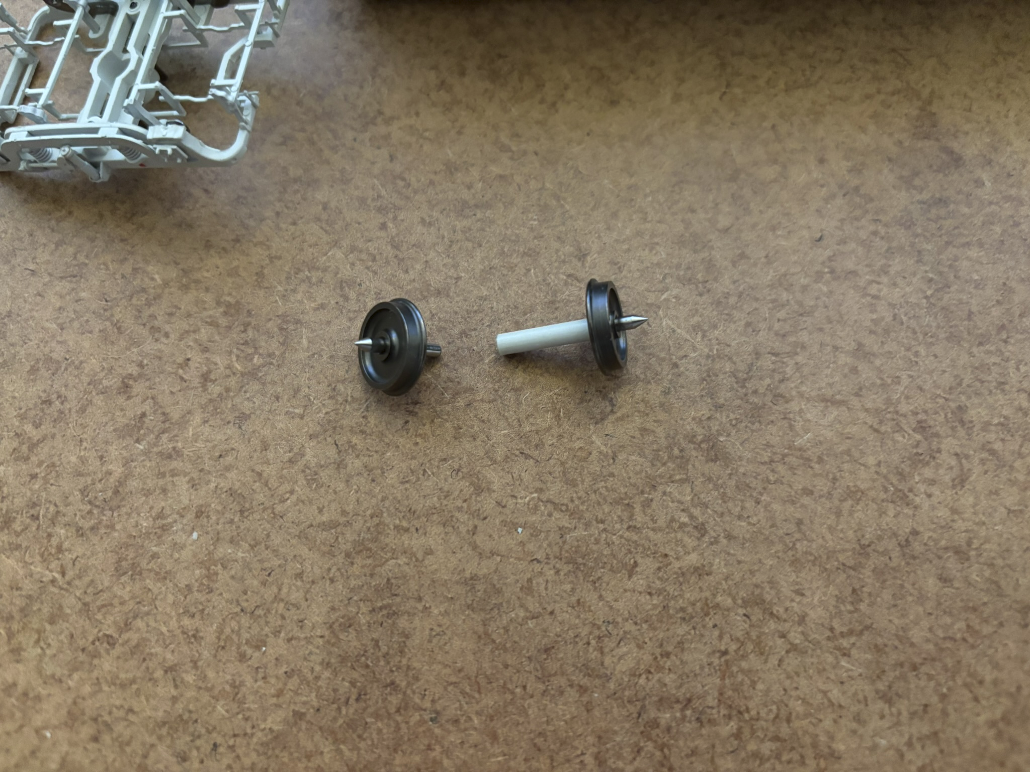
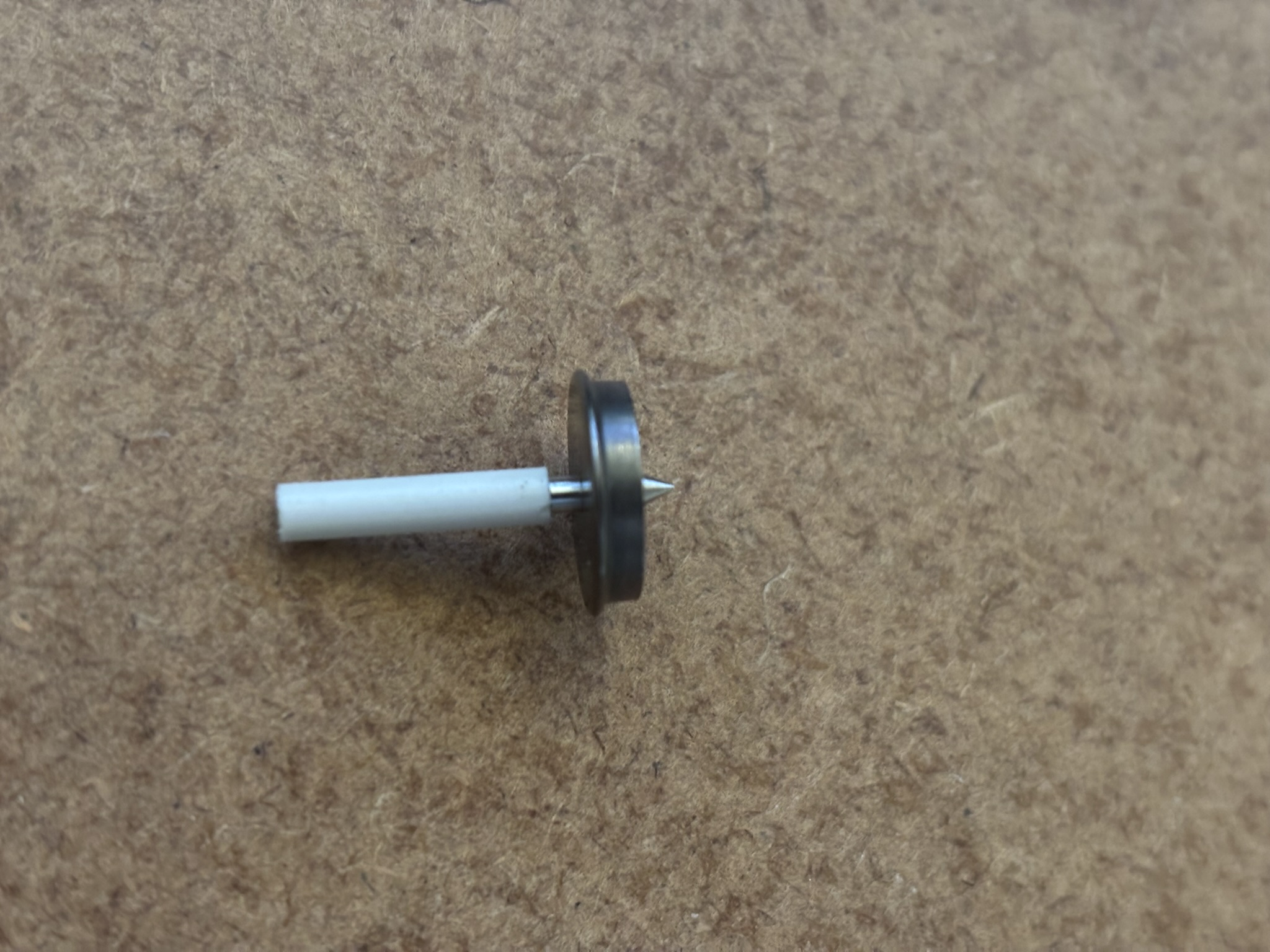
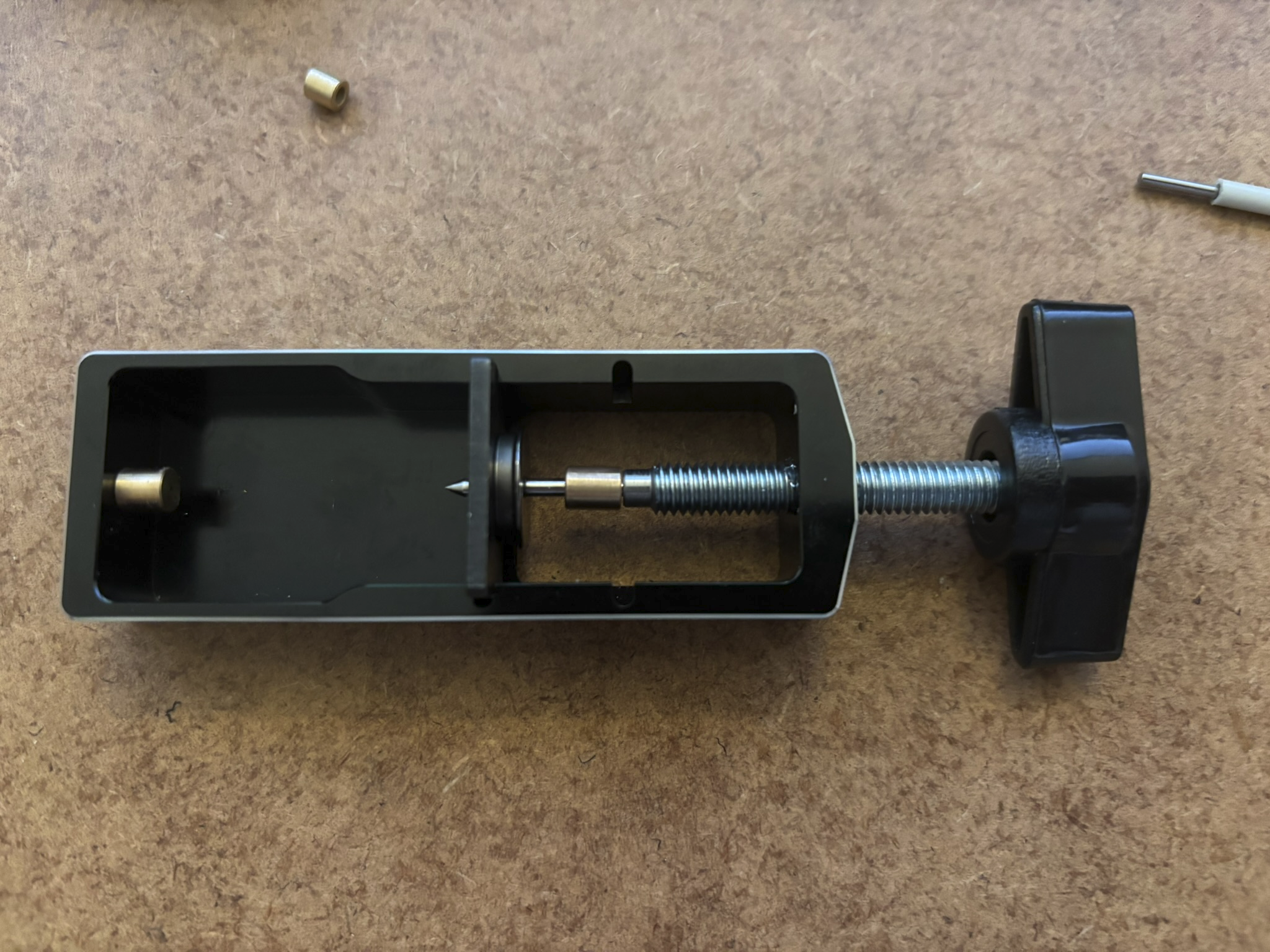
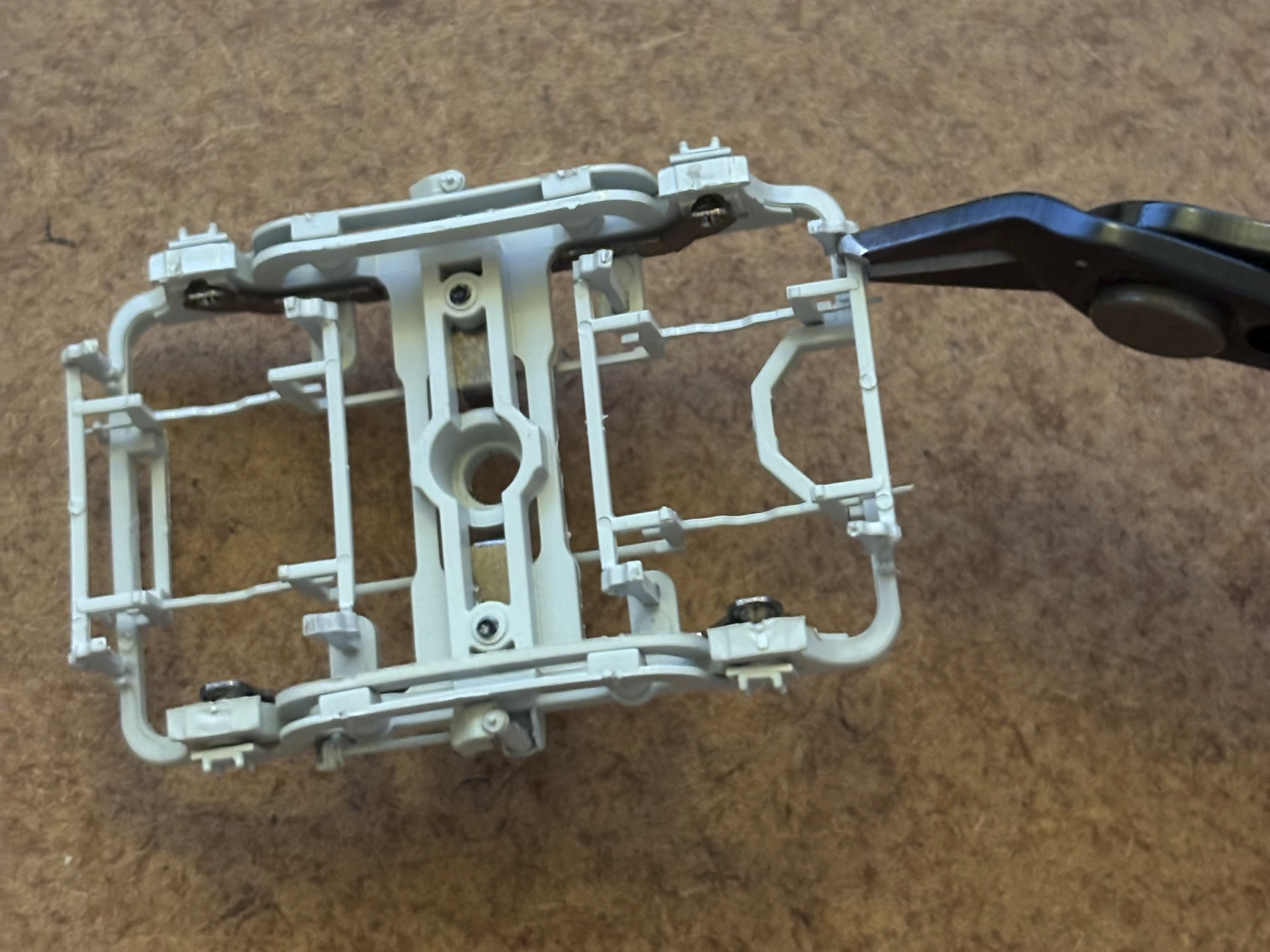
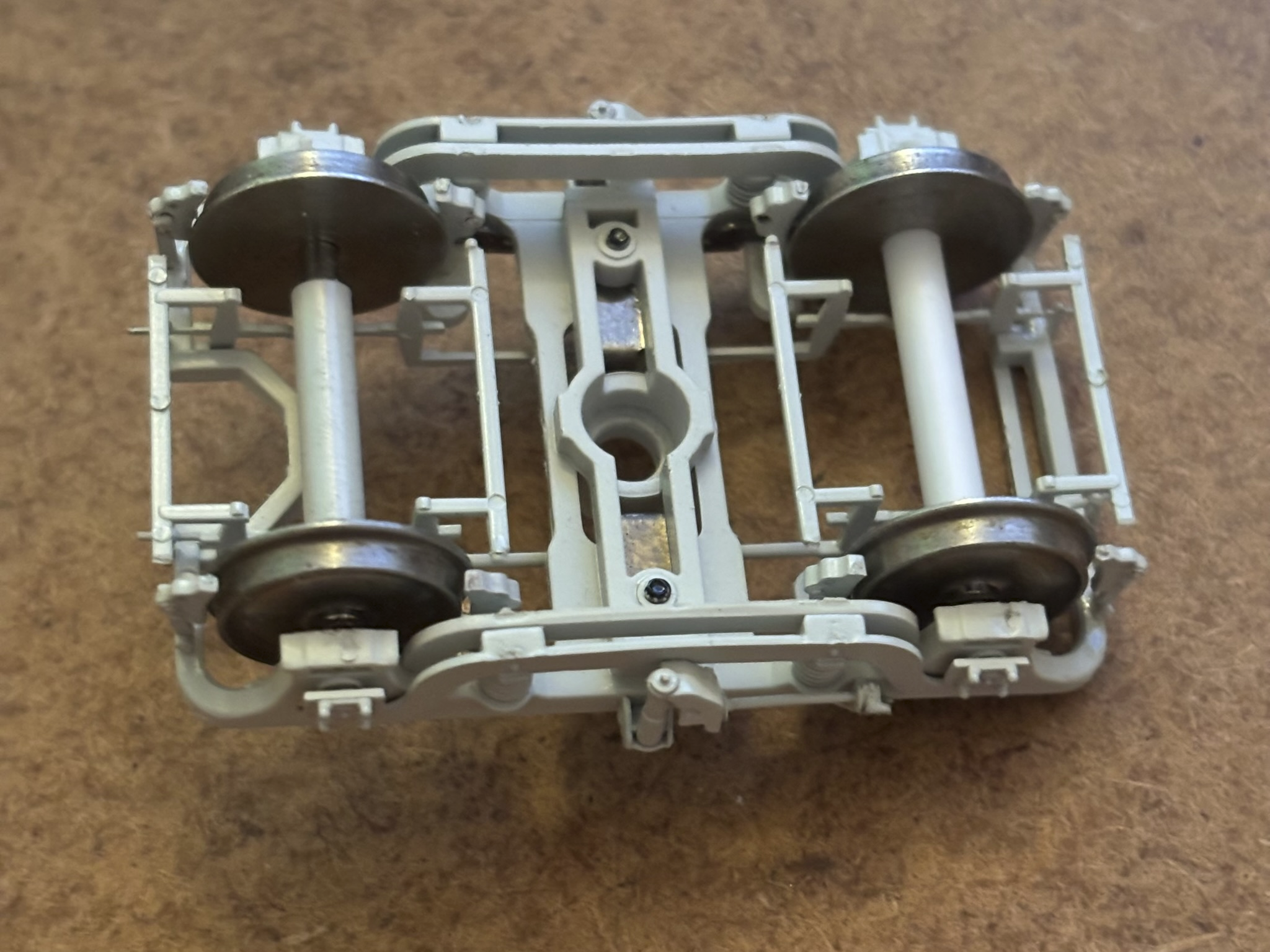
I finally got around to properly regauging my Park Royals. I used Alan Gibson conductive EM wheels since I personally don't like the look of NMRA code 110 wheels, and the process should be the same if you're using P4 wheels. Anyone who wants to regauge the factory wheels can follow Mol's post above as a guide instead. To start disassembly of the factory wheelset I gently pulled the two halves apart with my hands. This is enough to pull one of the two half-axles out of the insulating sleeve. To pull the other half axle out it is actually a bit more difficult. DO NOT just grab the sleeve with your pliers and pull, see my previous post for the consequences. First I pulled out the wheel a bit to create a gap between the back of the wheel and the sleeve. The throat of my puller is not wide enough to fit the sleeve, but I've come across this problem before so I have a short length of aluminium tube that I use for this purpose. Once there is a bit of a gap I put that in my puller and used a small length of 1.5mm diameter rod to push the remaining half axle through the sleeve. Once the two half are out of the sleeve they can simply be pressed out through the wheel to get a completely disassembled wheelset. I pressed two nice shiny AGW wheels onto the half axles. These are not quite as tight a fit as the factory wheels, so take care when pressing that the wheels go onto the axles straight. I pressed them in a little further than necessary; it is very easy to pull them back out once the wheelset is reassembled, but nearly impossible to press them further in. (Apologies about the out-of-focus photo for this one.) Then I gently pushed the two half-axles back into the insulating sleeve bit by bit, measuring the total length of the axle as I went. I made sure the sleeve was approximately centred so both half-axles are firmly held in position. The overall axle should be 28 mm; 2x 13.5 mm half-axles with a 1 mm air gap inside the sleeve. Once the axle length was correctly set, I pulled out the two wheels to the correct back-to-back, 19.3 mm for EM in my case. Take care not to put any pressure on the pinpoint as you could easily mess up your axle this way. I use a 1 mm inner diameter brass bushing which I have given a suitable chamfer on the inside. To replace the sleeve I broke I cut a small length of polystyrene tube. This is nominally 1/8" outer diameter with unspecified inner diameter, but snugly fits the half-axles. This doesn't grip the axles as well as the proper sleeves, so I cut it to the same length as the back-to-back to prevent the axles from creeping in any further. The slightly sprung bearings on the bogie should prevent the axles from moving any further outward, so this should be sufficient. I am nothing if not consistent at being 0.01 mm over on all my measurements Before installing the freshly regauged wheelsets, I modified the brakes as these foul on the flanges of the 'correct' gauge wheels. First step was to snip the linkage from the outside brake shoes. In my Park Royals the linkages are not sufficiently glued to the inside brake shoes, so they can be gently pulled apart. Once it is loose the linkage piece can be 'unhooked' from the frame on both ends, gently manoeuvred back and forth, and eventually lifted out from the top side of the bogie. Then I gently snipped off the 8 brake shoes. For the outside ones I tried to cut the brakes along with the pivots to keep them as one piece. This worked for some but not for others; for some the glue bonding them together was not enough to prevent the tiny pivot piece from flying away. To prevent the regauged wheelset fouling the inner brake mounting pieces I had to file a small chamfer on the outside edges which you might be able to make out in the photo below. This is definitely necessary if you're using RTR or EM wheels, but you might be able to skip this if you're using P4 wheels. Then the final step is to install the wheelsets and carefully glue the brakes back in place. Mol's technique of using fine wire above is probably stronger, but I was lazy so I just used Superglue and glued the brakes into position. I haven't tried bisecting the linkage and gluing it to the brakes yet, it's something that won't be visible unless you have one heck of a derailment anyway, but I will probably end up doing that similar to what Mol showed above. And here is the end result installed under the coach:
- 29 replies
-
- 11
-

-

-
This one sold recently for £580/€675: https://www.ebay.ie/itm/147282572613 It's a seller's market for 071s at the moment.
-
There is also an EU-based etcher I have in the past, Hauler Ltd in the Czech Republic (https://www.etchworks.eu). Their standard sizes and artwork requirements are a bit different from PPD but it's not too difficult to convert. I've always used the old Hollywood Foundry guides to creating artwork. They don't seem to be available online anymore but I'll upload my copies to the resources section later this afternoon. Of all the etched kits out there, I reckon only a small portion of those have been digitised, while I doubt any etching place will accept any new artwork in anything other than a digital format these days. So any slight tweak or alteration, or moving to a new etcher, or whatever else would probably require digitising the whole thing. I reckon this might well be one of the reasons we're seeing some etched kits disappearing. Many of the people who were skilled in designing hand drawn etched kits in the past may not be familiar with the digital methods used today. I think we could well see an uptick eventually as the amount of digital artwork starts to fill the gaps left by the shrinking number of hand drawn kits. Of course there are many other reasons such as the rapid improvements in 3D-printing, the increasing number and detail of RTR models, etc. Personally I'd love to have a go at making some etched kits at some point, although I have too many other projects going on right now.
-
I had hoped to have the chassis finished by this weekend, unfortunately things didn't go quite my way. I could tell the supposedly 'press fit' worms were tight on the motor shaft, but I figured it would be grand It was not grand... To make matters worse I managed to damage the worms trying to get them back off the motor shaft. And while I do have spare motors, I do not have any spare worms. Oh well, lesson learnt, I'll give them a pass with the reamer next time. Unfortunately this does mean I'll have to wait for some new worm wheels to arrive
-
The 16.5mm gauge OO track most people use is slightly under scale for standard gauge. It's actually really HO scale track that we use in OO. Some modellers in the UK use EM and/or P4 track and wheels which are more accurate to scale. In Ireland the 'problem' is doubly bad since we use broad gauge track, so the scale accurate track gauge should be 21mm instead of 16.5mm. So some modellers (like me) who care too much about accuracy or just like the extra challenge will regauge stock to run on 21mm gauge track. I'm sure you can find a few videos around the place on EM/P4 conversions (especially from UK modellers). It usually involves pulling the wheels out to the correct gauge, but depending on the model can require some more significant modifications. There are quite a few posts on this forum about people converting their stock too.
-
21mm gauge wheel sets for IRM Park Royals and Mark IIs
lucas replied to lucas's topic in Irish Models
First attempt at regauging hasn't gone so well... Looks like the sleeve just keeps the axles insulated from each other using a friction fit on the axles. There is no internal spacer keeping the axles apart. Even when set to 16.5mm there is a small gap between the sleeves and the back of the wheels, so moving the wheels out shouldn't make the axles any more likely to move within the sleeves. We just need to be careful not move the axles within the sleeves during the regauging process. I will be trying to get some conductive EM wheels to replace the code 110 factory ones. Although EM track is very tolerant of coarser wheels they are pretty massive and unsightly in my opinion. It's going to be pretty difficult to fit new wheels without removing the axles from the sleeves, so now I just need to find a reliable way of getting the axles out without the sleeves exploding on me.
-
I received my Park Royals this morning. They look amazing, but I think I can see what's been causing derailments for others. One of the brake lines on one end droops down and fouls the flange of one of the wheels: IMG_3119.mp4 This is a lot easier to see on the green coaches with the grey brake lines. The video shows the worst affected of my PRs, but all of them seem to have some level of contact with the wheel. This only happens at the end where the two lines cross over, the other end has enough clearance. I have not actually experienced any derailments, but I could see this causing problems especially in combination with some iffy track. I will be regauging mine so the wheels will be moved out, well away of these lines. But otherwise I reckon a drop of glue to stick the brake line to the underside of the floor might be the best solution.
- 769 replies
-
- 17
-
-
-

-
"Voiding the Warranty" - Mol's experiments in 21mm gauge
lucas replied to Mol_PMB's topic in Irish Models
Too late... Just finished respraying mine in pink -
Yes, the frames are spaced with 25mm between
-
I found it lying around in the bottom of my stash. It does have lights and recessed cab handrails (or at least the recesses, the handrails themselves aren't included). No chassis of course; it has mounting for a Black Beetle/Tenshodo motor bogie, but that's not the most suitable chassis for a slow running shunter. I don't have the drawings so I can't speak on the accuracy, not sure if they're available somewhere? I have had some vague plans of building one in 7mm scale at some point and have mostly just been keeping this little guy around as a reference/reminder.
-
There is the DC Kits resin one, which I believe Mike Edge created the masters for (possibly from the Worsley Works kit). It's a G611 just like the WW kit, while Silver Fox is a G601. Not sure if they're still sold though. I have an unbuilt one lying around somewhere here...
-
21mm gauge wheel sets for IRM Park Royals and Mark IIs
lucas replied to lucas's topic in Irish Models
Interesting that they have 2mm axles unlike the Mark 2s. They might not be so difficult to regauge after all so. Is there anything inside the sleeves preventing the axle ends from moving further in? One thing I worry about is that the axles will slowly work their way further into the sleeves over time, changing the BTB and overall axle length, but also running the risk of shorting out internally. I'm still patiently awaiting my order, but looking forward to doing some experimentation when they arrive. -
Yes that is the most obvious difference, but there are a few others. I have come across at least 3 different variants of the bogie frame. There doesn't seem to be any clear pattern for which appeared on which loco, with two different variants often appearing on the same loco. In fact they seem to have gotten swapped around over the years, presumably when multiple locos were in Inchicore at the same time they ended up with each other’s bogies. I have a spreadsheet of which loco had which bogie type(s) throughout the years, but it's still a work in progress. I'll share more details when I have a better picture myself. All I'm saying for now is IRM better have their eyes on the ball
-
Don't get me started on the bogies, I've noticed quite a few variations there too Expect another post on that once I've had a bit more time to research
-
That's good to know, thanks! I hadn't come across photos of them operating in multiple or push-pull so I was wondering what they were intended for. Edit: I actually found (what I assume is) the picture you're talking about. B233 working multiple with B192 on p. 36 of Irish Metro-Vick Diesels by Barry Carse
-
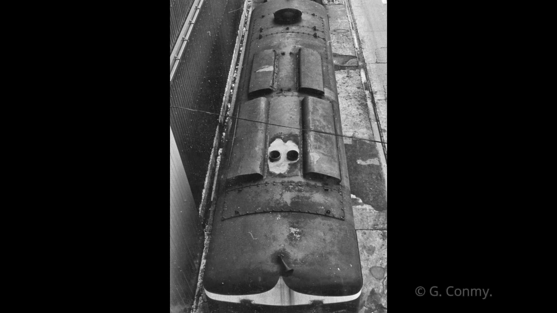
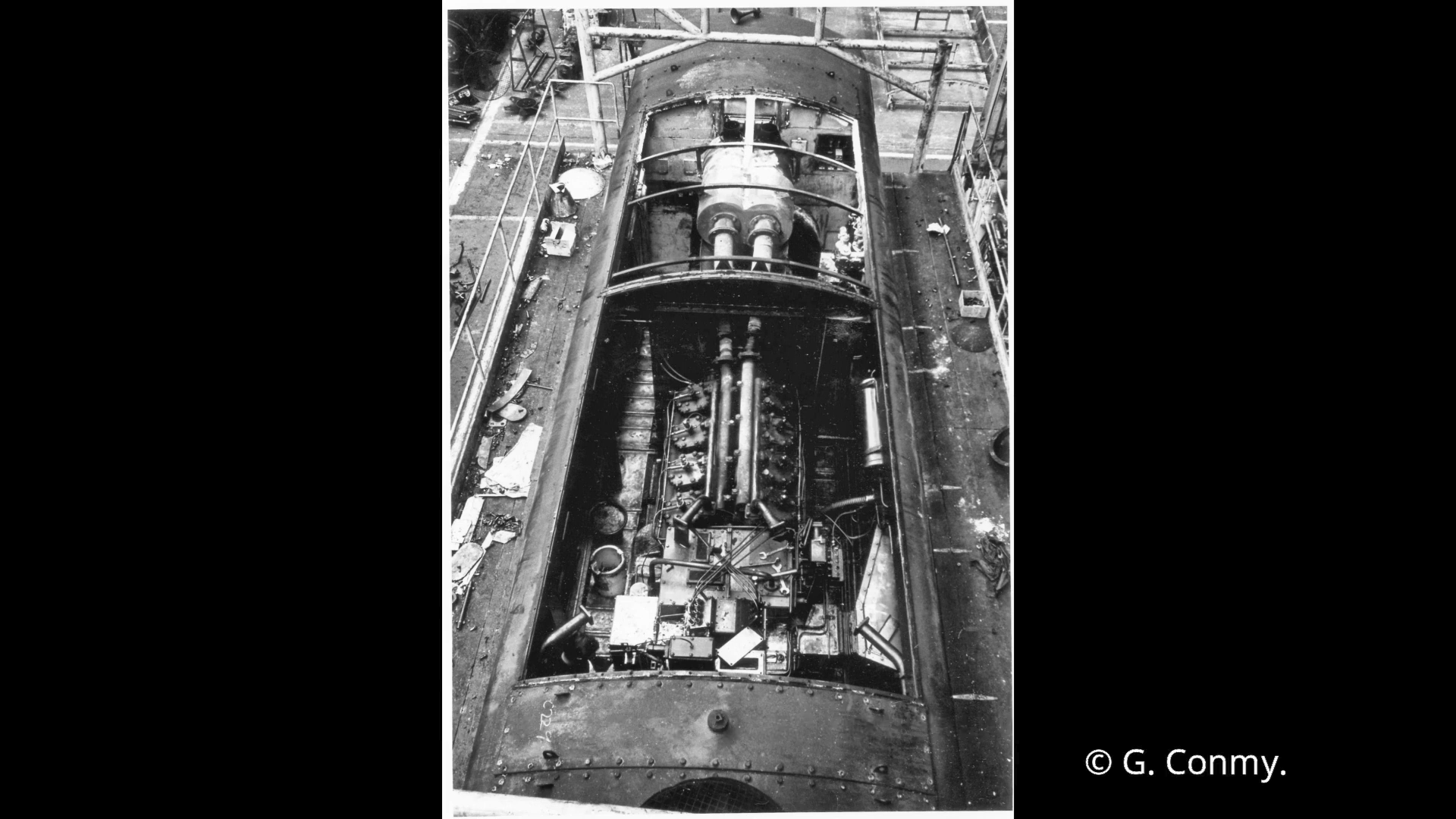
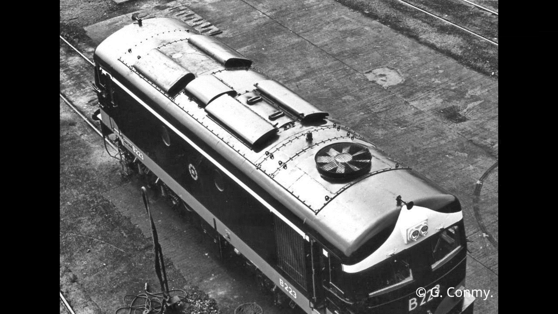
Not much to share in terms of progress of late. I have been working in parallel on both the chassis and some detail parts, but I'll wait until I have a bit more progress before showing that off. In the meantime, I thought I’d share some research I’ve been doing on the differences between the Crossley- and GM-powered locos. I’ll be modelling the original Crossley-engined locos, but many of the best photographs are much more recent. So it’s good to know what has changed and what hasn’t so I know which photos I can rely on. Also, I just find it interesting There’s a fantastic video from Gerry Conmy on YouTube with a lot of pictures showing the re-engining process: https://www.youtube.com/watch?v=eL1r5Ipeb1w. I have posted some screenshots of the video below where I haven’t been able to find other images, but there is a lot of good material in the video and it’s well worth a watch. Roof changes As I mentioned in my original post, the roof seems to have undergone the most drastic changes during the re-engining process. It is also one of the least photographed parts of these locos, but probably the most visible on a model. As-built, the C class rooves had 5 removable panels. Starting from the no.1 end (the radiator end) there is a small panel containing a relatively small 6-blade radiator fan, a small panel containing the header tank filler, the largest panel with some blank space and the engine compartment vents, another large panel containing the generator compartment vents and the exhaust, and finally another small featureless panel. The vents on the engine compartment roof are similar to those on the A class and allow some ventilation for the engine since neither loco has any vents on the body side. The generator compartment roof vents are unique to the C class. The one on the left-hand side seems to be for the exhauster; the A class has an extra grille on its body side for the same purpose. The one on the right is less obvious. It could be to allow some ventilation for the load regulator’s resistor banks which are on that side, or perhaps it is just there for symmetry. The A class doesn’t seem to have any equivalent ventilation near its load regulator as far as I can tell. The exhaust actually stretches above the generator and exits on the far opposite end of the generator compartment, as can be seen in this picture with the two larger roof panels removed. Note the loco is facing the opposite direction compared to the image above. When the much more powerful GM engines were fitted, the class had much larger radiators and a larger 8-blade fan installed. To accommodate this the roof panel containing the fan was also enlarged. The header tank filler panel seems to be the same size, just positioned a little further back due to the larger fan. The filler itself had changed, sticking out noticeably higher than the old one. The large engine compartment panel was fractionally enlarged and modified to accommodate the new engine. The vents seem to be the same size, but were moved to the opposite end of the panel, nearer the radiator fan on the no. 1 end. A hole was cut between the two vents for the exhaust silencer with two slot-shaped exhaust ports. Unlike the Crossley, the exhaust sits right above the engine. An extra 'hump' was also added on one side behind the vents to cover the new Roots blower. The A class has two such humps, one on either side, but the C class has just one. With the larger fan and engine vent panels, the generator vent panel was cut down to compensate. The panel and the vents it houses were reduced to around ⅔ size post-transplant. The two holes for the old exhaust ports were also removed. The last small blank panel seems to be the only one that went completely unchanged. Here is a picture demonstrating the changes. You can clearly see the weld lines from where things were modified, including the two spots where the old Crossley exhausts used to be. Other exterior changes As mentioned, the GM engine required the fitting of larger radiators which also meant the radiator grilles got enlarged by a considerable amount on both sides. A new external fuel gauge was also fitted on either side requiring a small cutout in the bottom edge bodywork near the middle. Another smaller pill-shaped cutout nearer the no. 1 end was removed on some of the locos, but not all. I think this was probably to access the radiator drain valve, but I’m not entirely sure. Along with the transplant, the locos underwent a few other changes during the process. This included large GM headlights fitted to the ‘forehead’ on either end of the loco. This is probably the most obvious external change, but there were quite a few others too. As built, they had a fairly minimal amount of equipment on the buffer beam, just a vacuum hose. During the transplant an MU (multiple unit) socket and air brakes were fitted to allow them to operate push-pull trains with the AEC former-railcars. A handful had previously been fitted with ETH (electric train heating) sockets, but these were all removed during the transplant. The locos were also fitted with staff catchers. Unlike the A class, the Cs never had them previously. And of course, they were given a new lick of paint and a new B2XX classification to denote the increased power. You can clearly see most of these changes comparing these two photos: Note 206 did not have small pill-shaped opening on the body side removed, while most others did. Perhaps if I was modelling a GM-engined loco I’d have the motivation to go trawling through photographs to figure out exactly which ones had this opening covered up and which didn’t. The picture below shows C201 in Inchicore post-transplant but pre-repaint, and you can clearly see this opening has been freshly covered up: https://www.flickr.com/photos/irishrailwayarchive/54778612658/ Maybach Transplants C233 and C234 were given initially Maybach engines in the mid-60s. At the time GM weren’t willing to sell engines on their own, just complete locos. Apparently, they were worried that GM engines fitted in iffy machinery would harm their reputation. They did of course change their minds a few years later when CIÉ had proven to be a loyal customer. The Maybach engined locos shared some exterior details with both the Crossley and GM locos, but also had some of their own unique changes. Similar to the GM locos, the Maybachs had a larger fan installed on a suitably enlarged roof panel. However, the rest of the roof layout stayed mostly the same as before. The vents were perhaps slightly repositioned, and it seems like some of the blank space on the largest panel was removed to make room for the larger fan. I can’t find any good images of the roof showing the exhaust. I seem to remember stumbling upon an image in the past showing a singular round exhaust, but I could be mistaken. Larger radiator grilles were present on the sides similar to the later GMs. The same external fuel gauge was also fitted. And the pill-shaped hole seems to have stuck around on both 233 and 234 until their later GM transplants. An MU socket and air brakes were added to the Maybachs too, but the MU socket was in a slightly lower position. This required relocating the dummy coupling for the vacuum hose to the opposite side so it wouldn’t be in the way. One of the most obvious unique differences is the removal of one of the ‘porthole’ windows on the right side of the body. They also did not receive either the GM headlights or the staff catchers that the later rebuilds did. However, they did receive the B2XX reclassification. Here are some pictures illustrating the differences between front ends of the 3 variants. The first picture shows a Maybach- (left) and Crossley-engined loco (right) side by side. The second shows a Maybach- (centre) and GM-engined loco (right), with a GM-enigned Ar lurking in the background on the left. https://www.flickr.com/photos/152343870@N07/52050288065/ The two Maybachs did receive GM engines nearly 10 years after the rest of the fleet, along with their GM headlights. But I can’t seem to find any pictures of them with staff catchers, so they may never have had these. They did not lose all their Maybach-isms either. Here is are some photos of 233 and NIR 109 (formerly 234) showing the missing window and relocated vacuum hose still present long after being re-re-engined: https://www.flickr.com/photos/irishrailwayarchive/54777525252/ https://www.flickr.com/photos/152343870@N07/52094277983/