.png.c363cdf5c3fb7955cd92a55eb6dbbae0.png)

Maitland
-
Posts
132 -
Joined
-
Last visited
-
Days Won
1
Content Type
Profiles
Forums
Events
Gallery
Blogs
Everything posted by Maitland
-
Recognised the (fighting) tank straight away, but couldn't remember the name. Whippet. As a matter of interest, what CAD program are modellers here using? I'm using Solid Edge. It's clunky and viciously complicated, it drives me nuts and it's going to send me to hell for bad language. And you have to update every 3 years or it stops working. But when it works it's accurate and the results seem pretty good. I've tried Freecad 0.xx - utterly hopeless - and 1.1 - less hopeless but hard to use, and the tutorials and documentation are very out of date. So what are the alternatives, good and bad points?
-
That looks nice.. now tell us how you print it..
-
Well, that's given me a lot to chew over. I've printed it out, and will be perusing it carefully. I must say, the matter of support is one of my biggest concerns at the moment. That and Madame's complaints about the smell...
-
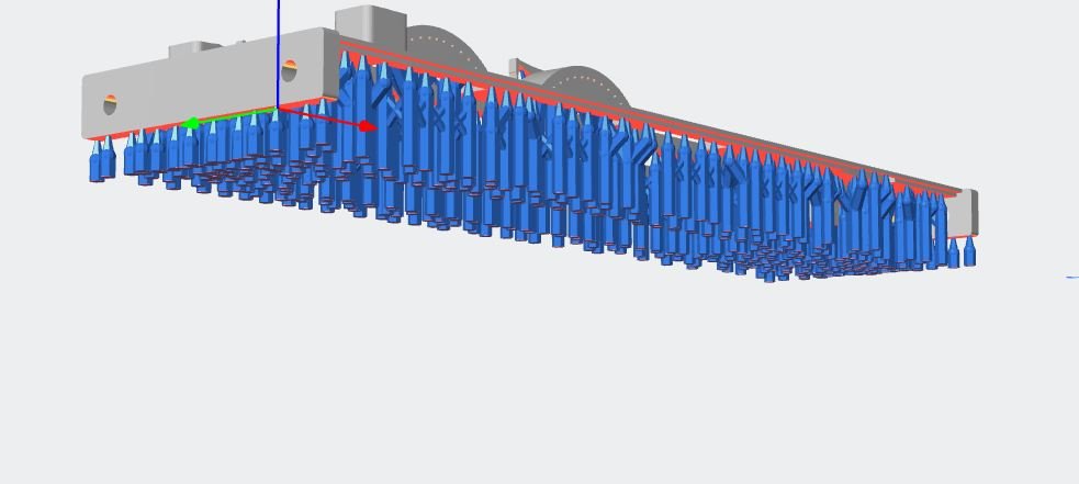
The drooping on the tank happened after I'd left it supported only by the buffer beams for a week or so. I've added a structural longitudinal support to the underside of the running plate, between the frames, but do I need a longer post- cure? The strips are all well and good for vans etc where it's all outline, but I see your van has a floor.. how does that get supported? As I've said, I'm very new to this business, and so far I've allowed the Anycubic program (as we used to call apps) to generate supports. It generates far more of them, pretty randomly. It supports, for example, the external framing. I don't know what I can get away with. I also note your brake gear and stays between the W irons etc.. it looks very flimsy, does it last? What about things like lamp brackets, smokebox door handles, grab rails?
-
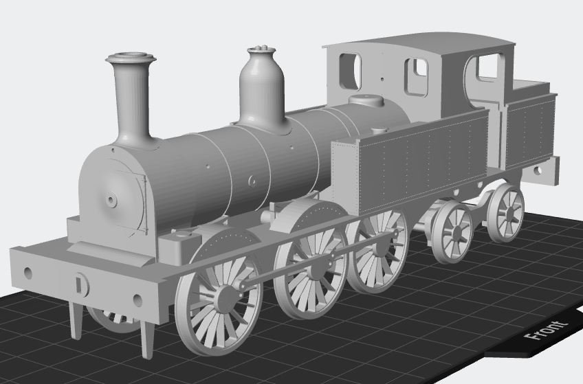
Must apologise about slow progress on Sligo tank. Long Lapland (Sapmi) trip, folk festival, grandboy minding and suchlike commitments have kept me away. Plus the fact that when I do work on it, I keep changing my mind. I'm looking to do the cab, tanks and running plate all as one now. So here's a screenshot from Photonic Workshop just to encourage me to get going properly again. Of course I don't plan to print it like that, it's just to check that the bits actually fit together. They don't, a bit of tweaking to do.

-
Sorry about my lack of understanding, but I can't see what this has to do with Terry McDermot?
-
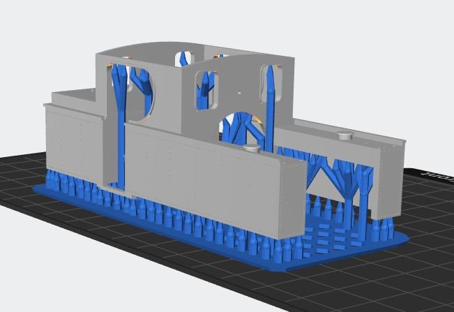
I used automatically generated supports from Photon Workshop, don't understand enough to do my own yet! Some obviously silly supports were edited out. The supports inside the tanks and those inside the splashers were a right b*** to get out.
-
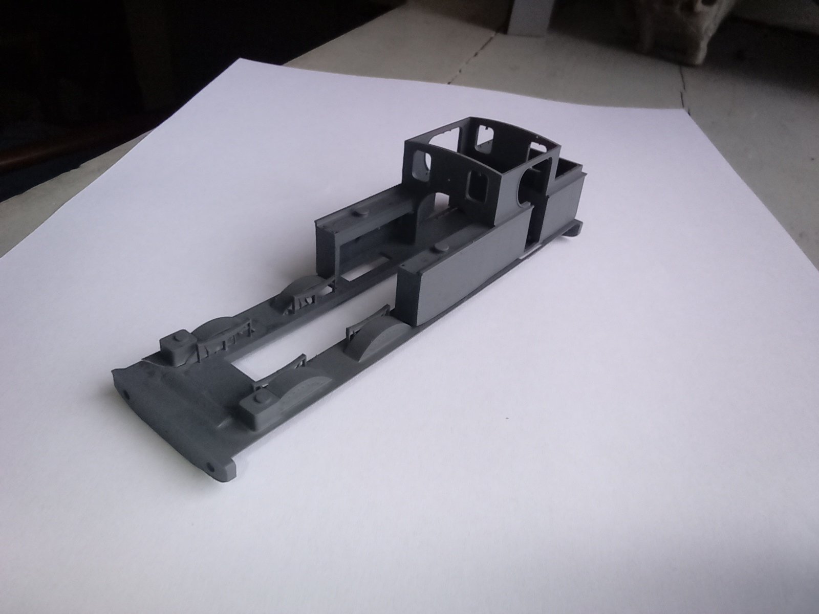
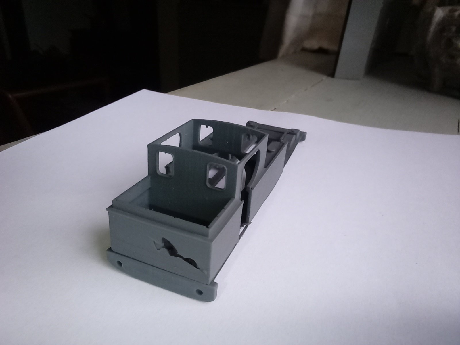
Close, but no cigar... Apart from the hole in the bunker back, which is my fault (I dropped it while releasing it from the build plate) the faults are: the flaws in one side of the tank - it curves slightly at the front corner. The location tab under the cab door failed to print on one side the buffer beams have that "interesting" curvature on the bottom edge - it's supposed to be straight. The deck isn't rigid enough - it droops. The location tab serves the secondary purpose of making the cab itself a bit more rigid instead of depending on the thin connection over the door, so I'll make it into a flat plate recessed into the floor. Per ordure ad astra.. -
-
Semis were what we called Stanier Duchess class 4-6-2s back when I was the little boy watching the big kids with ABC books tick off the namers. I never did really understand train spotting.
-
And that's true, but look back at the 50s and 60s and 70s, and Great Britain.. well, mostly, England and Wales. There were a lot of young, energetic, motivated people, with just enough backing, through mum and dad, the University grants, and a fairly lax social security system, to spend serious amounts of time doing stuff they wanted to do. This was the age of canal restorations, Talyllyn, Festiniog (before the f's proliferated), Bluebell, but particularly stuff like the Stratford Ccanal and Stratford Avon "restorations" that used methods impossible today. When a government realises that you can pay young and hopeless people to gain faith in themselves and marketable skills, at the same time as creating community facilities that create a positive feedback loop that keep that sort of thing going, the heritage thing becomes sort of obvious. Until then we're in the hands of small- shop grocer economics for the plebs, and wow-look-at-that untouchability for the superstars. Back in the 70s Ireland was full of idealistic backpackers- I was one- they will have told their kids in English, French, Dutch, German perhaps about wonderful quirky Ireland, that's where to start from to get their grandkids on a train singing "are you right there Michael". I've no solutions, but I think the idea of generating infrastructure by using otherwise unused talent - unemployed kids, hey, what about refugees- is worth thinking about.
-
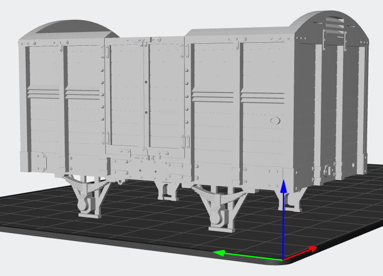
Looks to me like the Hornby van has a single radius arc, but your van seems to have a multi- centre or elliptical end. You might have to empty several beer cans to make sure you get one that's properly emptied. Real ale or cheap Rioja man myself.... Oh and by the way I worked out why the ironwork was missing on the van. It's a long story, but essentially I used the wrong stl that didn't have it on. Version control?
-
At least I know what I'm aiming for. I'll thicken that whole side up. Sacrifices some of where I thought electronics might go though.
-
Latest files posted anyway. I've taken the fittings off the boiler, and made them separate, so they won't need a pile of supports to cut off. I think the boiler might be best printed vertical, arse end first. I think I've been a bit too clever with the boiler fittings though. I made a little recess in the boiler and thickened the fitting to fit it, but show a little of the rim. The idea is to avoid very thin surfaces with supports just where they meet the boiler. It worked for the chimney and the dome, but I think I'll change it to make the bottom of the recess flat
-
About supports: I'm pretty sure Photon Workshop uses AI to create the supports. For a start, it supports things like individual rivets, but nothing like consistently, , and it doesn't do it on both sides of a mirrored design. It puts in little support branches that, like the Leek and Manifold, start nowhere and end at t'same place. But I haven't a clue yet where to put them manually, so I've got to start somewhere. I might try a downgrade to Photon Workshop- it's possible the latest release is a bit experimental. As for accelerations etc, I haven't found them in any setup yet.
-
Hang on a mo, I'll post the latest stls on Github. You can see the striations better in this photo. Both horizontal and vertical.
-
Not exactly achieved perfection so far. Suspended until I get a whole load more IPA and wife is out (she doesn't like the smell - of the resin, I mean). This was done with the Mono 4, standard resin and settings as Photon Workshop default (the biggest lump of loco body printed so far), then with thinner layers (0.03 v 0.05) and bigger support contact areas for the rest. It didn't seem to make much difference. In both cases I ended up with a lot of resin stuck to the FEP film. One problem seems to be that the print eventually peels away from the build plate. Levelling? I wonder if tightening the levelling screws - necessarily done with one hand holding the plate down - is moving the plate slightly. Perhaps a spring in there somewhere would help. Some sites recommend slightly roughening the surface with fine emery paper. I've got a small sheet of glass somewhere to ensure it stays flat. Also I'll try PTFE spray on the FEP film to encourage it to let go. Room temperature hovers around 20 at the moment (this is the cool side of the house) but it won't stay that way, and I can't wait for a heatwave every couple of year. It was probably about the same yesterday when I did the prints. The detail achieved isn't phenomenal - the rivet detail on the tank scarcely shows up against the build striations and the ironwork on the van is missing in places. On the upside, the strength of the product is alright. Throwing it across the room didn't break it.
-
Any chance of a link to it, or is it a state secret?
-
Latest updates to MGWR van added at https://github.com/PaulBurkeIV/CADModels. Includes an assembly including chassis for information only. The chassis is totally experimental, having a rocker for 3 point suspension, which uses a virtual centre at the middle of the axle. I don't know without trying whether this can be made friction- free enough to work.
-
I saw those toothed retainers, and worried about heavily loaded cattle trains bouncing about as they went down inclines and releasing the brakes. As an irrelevant aside, did Hazlewood's crew survive the derailment in 1923? Comments on the practicability of the bearing location arrangement visible below appreciated.
-
Showers on trains - it'll be jacuzzis on the next batch of stock. And they just told me they were outing me as a collaborator. For God's sake don't tell the boys!
-
So I looked through photographs - not of the actual wagon I'm modelling, but lots of Irish trains, either goods only or mixed. I found no pictures of both sides of the wagon at the same time. The photo in Ernie Shepherd's book of a 1906 wagon shows a pivot (towards the right) but no apparent brake gear at all. It's possible that there was only a lever on one side, But I came to a statistical conclusion: nearly all the wagons with such detail visible had asymmetrically- mounted brake pivots, possibly a result of the smaller amount of goods traffic in Ireland, and their general poverty after the First World War and aftermath. And every single pivot was towards the left with the lever to the right, and no wagons in any photo had no brake lever in a train where such details were visible. Since there's a finite probability that wagons ended up getting turned round in the course of service, I conclude that they probably had levers both sides. I'll put two pivots in, and anyone with better information can use a sharp craft blade to remove one of them. Oh, and I forgot to add a maker's plate. I'll have to look at more photos for the probable location of that. A quick run through suggests they were on the body side rather than the solebar.
-
Here's a question: I'm just adding an anchor to hang the brakegear from. I note from the drawing I'm working from that the brake lever pivot is hung from a bearing well asymmetrical from the vehicle centre, unlike later wagons that had the central V iron and a mechanism whereby you could operate brakes on all four wheels from either side. So this van could only be braked on one side ... at a time? Or was the brake only on one side?
-
Resin prints can probably warp more than, say a brass kit - during printing or afterwards. You can probably get away with more with "normal" OO flanges, but P4 is more sensitive. And then there's my trackwork skills... Thanks for the clarification John. I'm now thinking in terms of adding printed W irons/ springs to the body print, with built- in pockets for metal bearings for those who can get away with it, and putting in a slot so the bearing can be slid in with the axle in place, then fixed with some suitable gunge. Hopefully of the sort that can be got out again with a needle. For others, a rocking frame with sleeve bearings on one of the axles can be part of the chassis assembly.
-
I was seeing how my prints turned out before designing the chassis. What I need to know is first, how flexible the material is for easing axle ends into bearing cups, but rather more than that how to achieve a good 3 point suspension for 21mm/ P4. BTW Rob that looks how I'd envisaged the thing. How long will it be before my printing's up to that?
-
Thanks John, ordered the protective film and will call at Toolstation next time I'm passing. I'll put off printing till I've got them. Daughter and g-kids here for weekend so I've got plenty to do anyway. Dry lube spray to printing side of PF film or non- printing side? Rob, don't do the small tank yet, having looked at supports I'm taking the chimney & dome off the boiler and making them separate components. Also I've decided my printed underframes are unlikely to work and looking at metal frames with turned spacers. That's part of my motivation for developing a one- off photoetch printer as mentioned in the etched kits thread, though it won't be done for this job. Traditional piercing saw and brute force I fear.