

murrayec
-
Posts
2,680 -
Joined
-
Last visited
-
Days Won
69
Content Type
Profiles
Forums
Resource Library
Events
Gallery
Blogs
Store
Community Map
Posts posted by murrayec
-
-
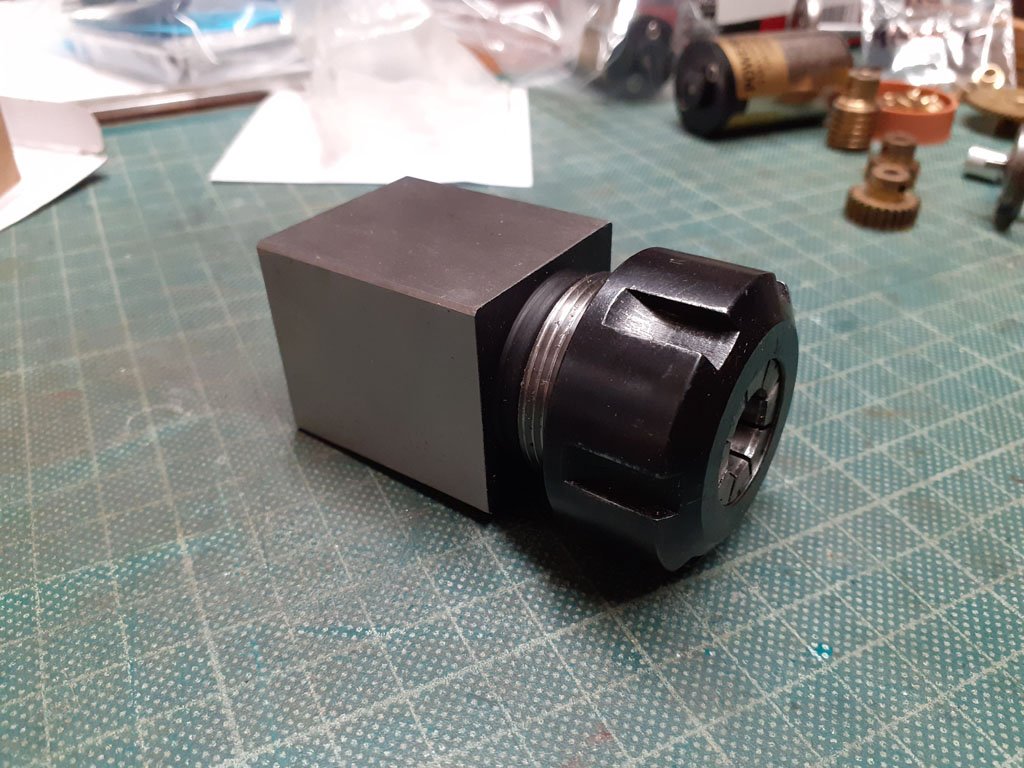
No need for a dividing head, use one of these in your mill;-

www.arceurotrade.co.uk
This unit, the nut and the correct collet mounted in your vice will do the indexing trick on the mill, you will have to do some reference marking to line up the squares when rotating the axle ends......
This collet size is ER25
Eoin
-
 1
1
-
-
Fleishman I think it was did a loco with directional drivers, when one changed the loco direction the current driver flopped down sideways and the other guy flopped up at the other end!
Eoin
Just saw that link above! I found it here above while Googling which manufacture did it

-
 1
1
-
-
It is possible to lengthen the Romford axles, access to a lathe is the best way, but it can be done without. All axles will have to be installed in horn blocks for it to work as the axle cannot be slid through the bearings when done.
Like Mr Holman style with his Gauge O axles
Chop the axle in half and sleeve it with a turned brass sleeve bored out to a close fit on the axle with allowance for the bearings, size and Loctite together in a V block, if no lathe use KS 5/32'' tube, the internal diameter is almost correct and the Loctite makes up the difference. Use off-cuts of the tube to support the axle ends in the V Block while gluing. Lining up the square ends is the critical bit- a gauge can be made to do this. One can also use a set of wheels to do the lining up but a narrow V Block is required that does not foul the wheels.
The drive axle can be sized by using the drive gear, Scale Link do a wide sleeved gear in their SLGS03 set, if you calculate where the grub screw hits cut this axle so that the screw locks onto one side of the cut axle, for maximum coolness a second grub can be installed to catch the other side of the cut axle. The above sizing gauge should be made deep enough to allow for the gear when lining up the square ends. Put in the grubs after the glue has set and do file a flat on the axles for the grub to land on.
oops! only file a flat on one side for the grub if doing the 'Two-Grub'
Eoin
-
1
-
-
19 minutes ago, David Holman said:
As a long time 7mm scale modeller, have more recently had to turn to Gibson wheels for some of my 3' narrow gauge locos as the Slater's range didn't cover my needs. Have found Gibson's to be ok and their service is decent. However, the lack of automatic quartering is a pain, while the wheels are not happy if you have to take them on and off the axles more than a couple of times. I have also found that tyres can come loose from their rims. Both can be fixed with a touch of cyano, but overall they are not as robust as Slaters. Or maybe I am just too heavy handed?
I had the same problems with Gibson wheels, so I made a set of axles slightly under size to use while the loco was under construction then on final assembly the correct axles are installed- makes life much easier.
Wonky crank pins can be avoided by using a screw guide when screwing in the crankpins- a thick piece of brass with a drilled clearance hole for the screw to be held perpendicular on the back of the wheel while installing. Drill the hole at the edge of the brass piece if the wheel has a rear boss so it sits flat on the wheel back.
Eoin
-
3
-
-
One of the tricks with soldering white metal is to use phosphoric/water flux, douse the area to be soldered with the flux, load the iron with 70deg solder and just stick the iron tip into the flux and in a millisecond when the heat gets into the metal the solder will flood the join. No touching the metal just the flux....
Eoin
-
 1
1
-
4
-
-
A good starter, it is white metal, slightly different process- 70 deg lead solder and one has to be careful with the iron as the white metal can disappear on you!
I suggest you buy his brass etch telephone box at the same time, that would start you off on etch brass also
You need to contact Des by email to order
I saw you note above about the cost of the books, I took a look and Iain Rice's books are available for around £22.00 on ABS books or Amazon- buy one at a time......
Eoin
-
 3
3
-
-
This may also be helpful;-
-
1
-
-
As Galteemore suggests a less complex etched kit is a better starting point for first time around.
Some reference books on kit building would be helpful, a bit of study before you start;-
'Etched Loco Construction' by Iain Rice, Wild Swan Publications ISBN 090686786X
'Locomotive Kit Chassis Construction in 4mm' by Iain Rice, WSP, ISBN 1874103100
'The 4mm Engine A Scratchbuilder's Guide' by Guy Williams, WSP, ISBN 0906867703
'Scratch-Building Model Railway Locomotives' By Simon Bolton, Crowood Press Ltd
to name a few good ones
I've included scratch building in the list as this knowledge is immensely helpful when working on kits.
Eoin
-
3
-
4
-
2
-
-
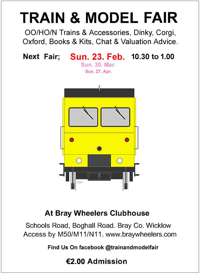
The March Fair Date;-
-
1
-
-
I have repaired several clockwork locos for a client, mainly replacing broken springs- a lot of work and not for the faint-hearted, the spring packs some punch if it gets free while dissembling the mechanism!
Eoin
-
3
-
-
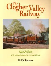
There are a few beautiful engineer sectional renderings of a sister loco, the boiler, Uniflow engine section, and text description in this book;-
Eoin
-
1
-
-
Be careful of using double sided tape- with some brands or most the glue drys out over time with the lamination coming free. PVA or paper glues would be a far better deal.
The edges can be covered with printed corner trims to walls and openings, with fascia & barge trims to the roofs
I agree with Darius43 about 'flat' corrugated roofs.
Take a look at Kevin Sweeney's thread for his building builds!
Eoin
18 hours ago, popeye said:You could say you've got your work cut out for you.

Cutting edge stuff
-
1
-
-
Visited all regularly
-
23 minutes ago, Horsetan said:
The WW Kit provides outer frames in the etches, but does not include frames for a chassis. Most builders, but not all, use a 'spud' or Blackbeetle motor bogies for power so all that is needed is a cross support to mount the bogie off.......
Eoin
-
1
-
-
-
15 minutes ago, Kevin Sweeney said:
The privy would be a quick build.
I love those old plans, they are not just stunningly accurate (compared to modern plans) they are also works of art in themselves. It strikes me I should start a thread somewhere on this forum for users to post and view such plans. Can anyone suggest the best section to start such a thread. It would be a useful resource for scratch builders.
Hi Kevin,
There is a 'Resource' section in Resources, maybe set it up in there?
or
In
- Home
- Resources
- RTR Models
- Buildings
Eoin
-
No, no, don't be putting pictures of him up! please
Eoin
-
1
-
 1
1
-
-
A link to Ken's Class 800 drawings;-
-
4
-
-
This was my go at the Worsley Works laminate etches, though a few of my own bits were added!
Eoin
-
7
-
 1
1
-
-
The Fair's Feb date;-

-
4
-
-
Yes thats correct, and as you can see that .4 of a mm makes all the difference

Eoin
-
1
-
-
OO is 1:76 so your scale factor from 1:1 is .0131
Eoin
-
2
-
1
-
-
4 hours ago, Darius43 said:
......Thing is, the dinosaur is missing…
One could go off script and use an elephant instead, it's trunk would be just as handy as the dino's tail.......
Eoin
-
1
-
-

Driving Wheel availability (4mm scale Irish steam locos)
in Questions & Answers
Posted · Edited by murrayec
What we all do here is magic, we bash & cajole atoms into jewellery......