

murrayec
-
Posts
2,571 -
Joined
-
Last visited
-
Days Won
67
Content Type
Profiles
Forums
Resource Library
Events
Gallery
Blogs
Store
Community Map
Posts posted by murrayec
-
-
Here are a few photos of a Gauge O Class A built by Brendan Kelly of the MRSI;-

Eoin
-
 9
9
-
-
Here is a link to Nicholas Sunshine's video of the exhibition;-
-
8
-
 1
1
-
 1
1
-
-
16 hours ago, Georgeconna said:
Quite a few 121's scattered about the show today for sure.
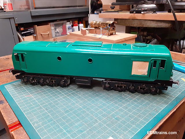
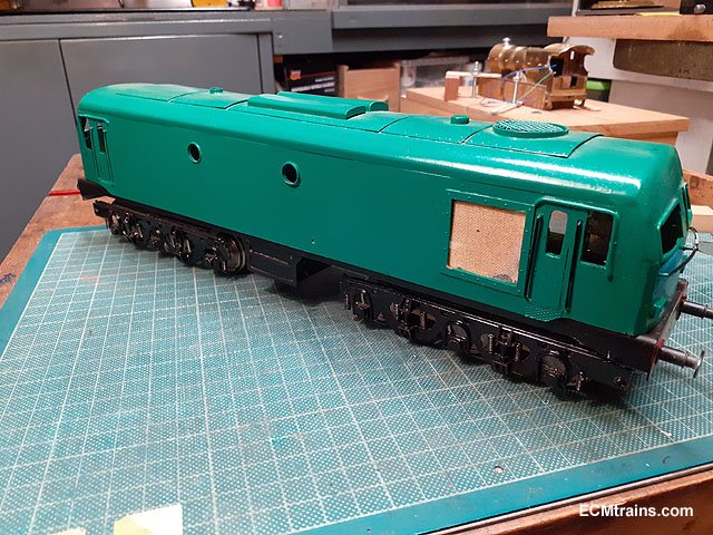
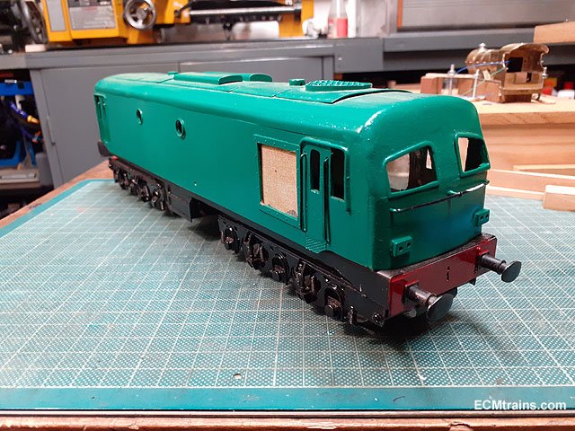
Bagged a nice Two Tone Green Baccy Class 47 with sound for 100 notes from Sean Ryan, Worth the trip alone, Just had a play with it there now and it is brand new!! Not even run!!
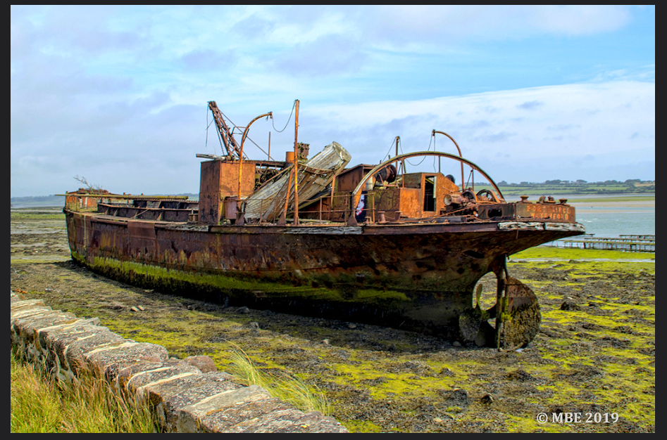
Enjoyed the day there, Left at 1745 and headed down to see the forlorn Port Lairge Wreck down in Saltmills then over to Portlaw to see the Malcomson's house, fish n chip in Youghal then. just in the door
Hi George,
Every time I went to say hello to you & your Dad at the show I got distracted, then you had left, good to see you quys!
Eoin
-
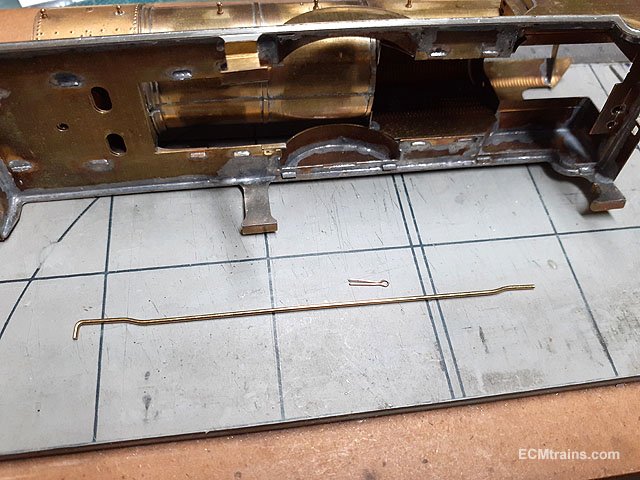
Back to the loco now, with some of the fiddly bits;-
The steam ejector pipe bent up from .9mm brass wire with a .3mm pb split pin to bracket fix it to the boiler body.
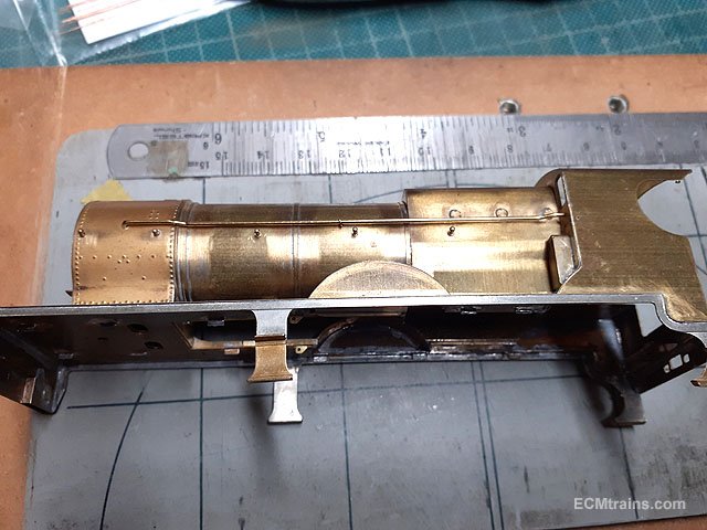
Test fitted, this will be painted separately and fitted after the boiler lining is done- I think, not decided yet!
Smoke box door handrail being fitted.
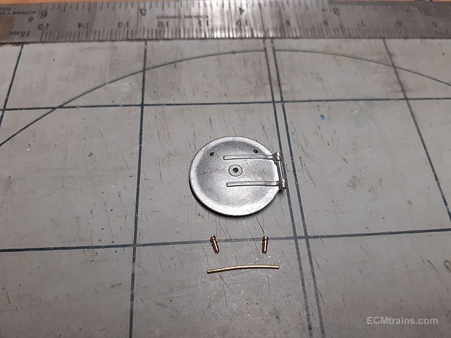
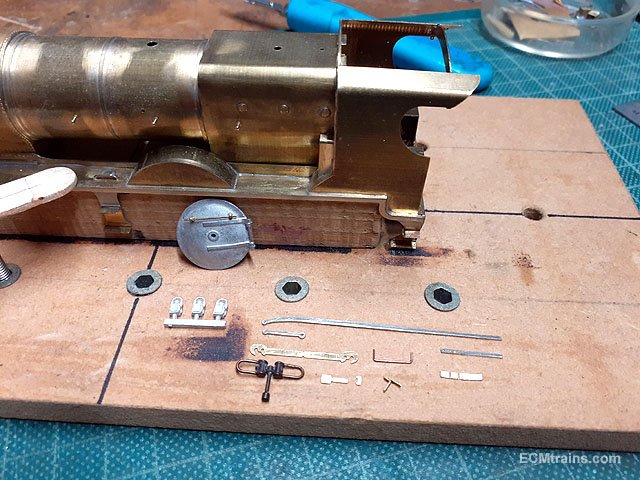
Some of the front end bits cleaned up and ready for test fitting, bending and soldering. The front footplate lights will follow later.
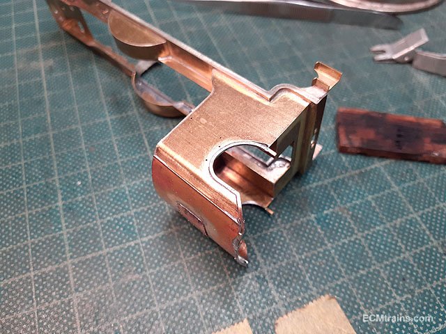
Sizing up the bridle rod, reversing lever and splasher mounting bracket.
The reversing lever is mounted across the footplate central space on a .7mm brass wire.
Cab roof, roof hatch, cabside beading, cab seats and cab doors cleaned up and ready for folding soldering and fixing.
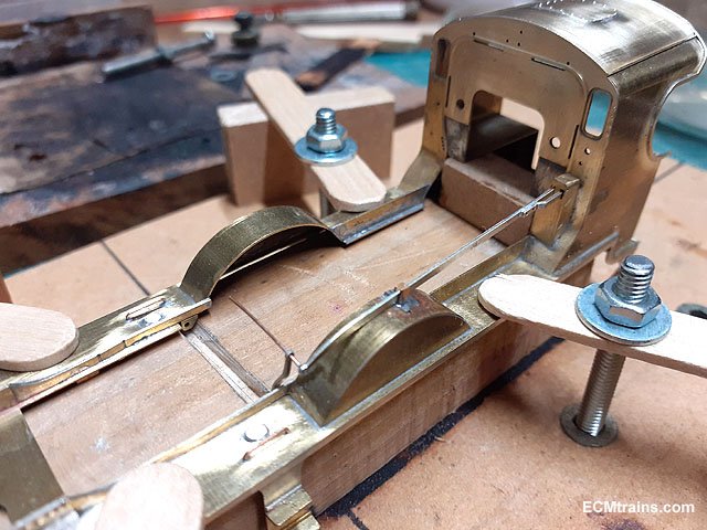
Roof tacked on the cab and adjusted before soldering fully.
The jig is very handy for doing this, using a bit of wood to hold down the roof and protect the fingers from the heat.
Roof hatch cover soldered on.
Cab sides and roof beading soldered on and needing a bit of a clean up.
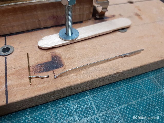
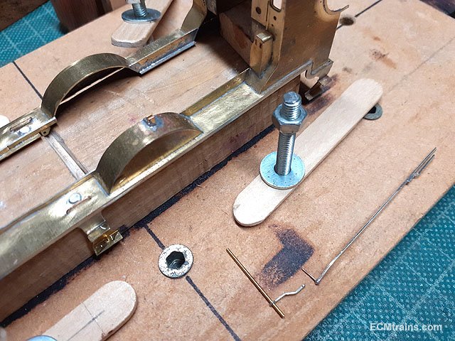
Bridle rod with the back fork bent up and soldered on, the front end has a .3mm pb wire soldered in the hole to hook up with the reversing lever. The lever is cranked outwards to meet the pin in the bridle rod end.
Splasher bracket folded up and soldered in position, the splasher has etched marks to locate the brackets position. The bridle rod and reversing lever will be fitted after painting.
Reversing stand and cab seats folded up ready for soldering.
Soldered, the reversing bracket crankwheel has a .3mm hand crank soldered on.
Cab side handrails being fitted after cleaning up the roof and beading.
Cab side wind shields folded up, with .5mm brass rivets for mounting on the cab sides.
Just before soldering the wind shields on I made up the cab end/roof rails with the cab side beading folded around the rails.
Then the wind shields were soldered on from the inside.
The rivets need cutting and filing flush inside the cab.
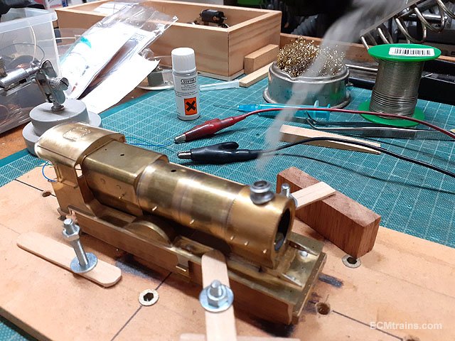
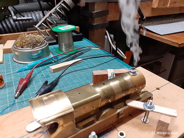
Testing the smoke generator before the chimney and the smokebox door are glued on, once these fittings are on there is no access to the generator again- so checking it now...........
First smoke......
Eoin.
-
8
-
3
-
-
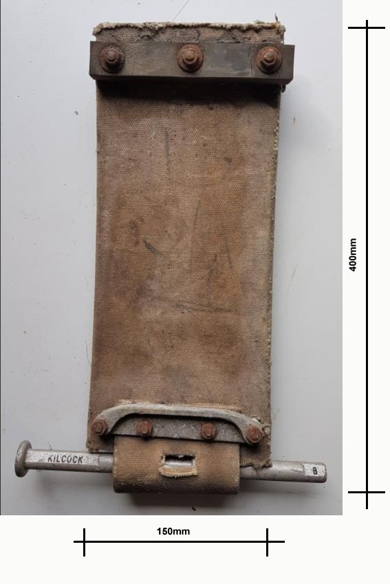
@fishplate7 Going by the chaps hand in the top image I'd say;-
and the leather or canvas being 3mm thick??
Eoin
-
2
-
-
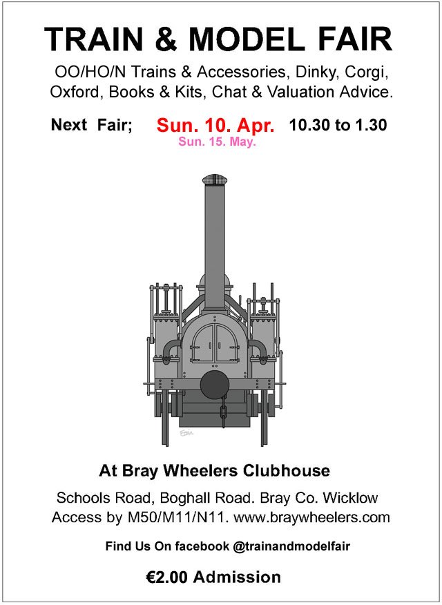
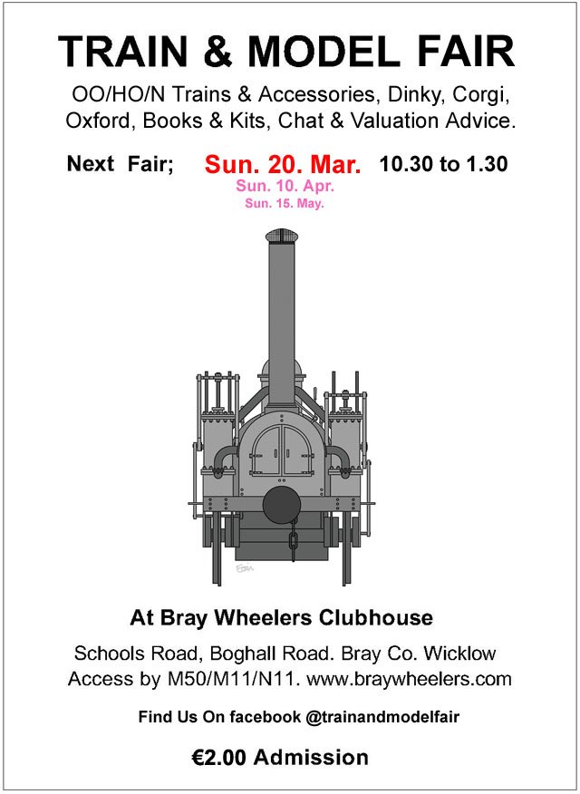
The April Fair date = Apr 10, 2022;-
-
2
-
-
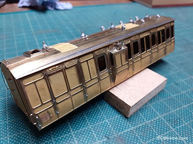
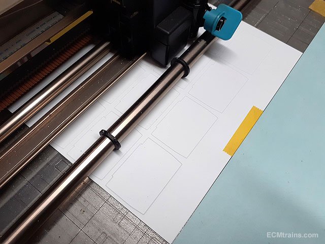
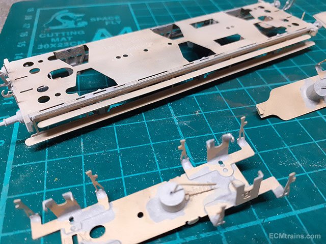
I have neglected to post photos on this thread for a while! So all the coaches are now assembled except for the last few parts described below.
The final soldered brass parts gone on - lamps on the roof of the duckets.
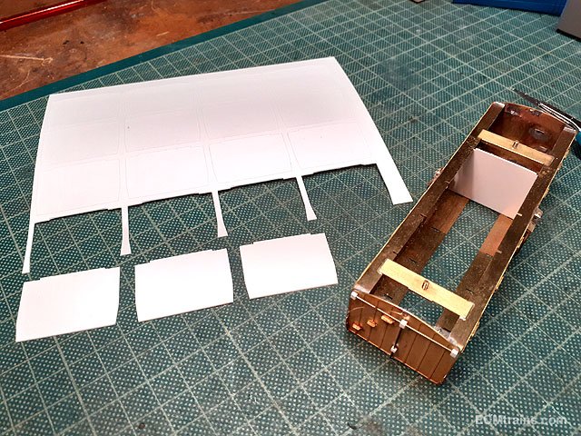
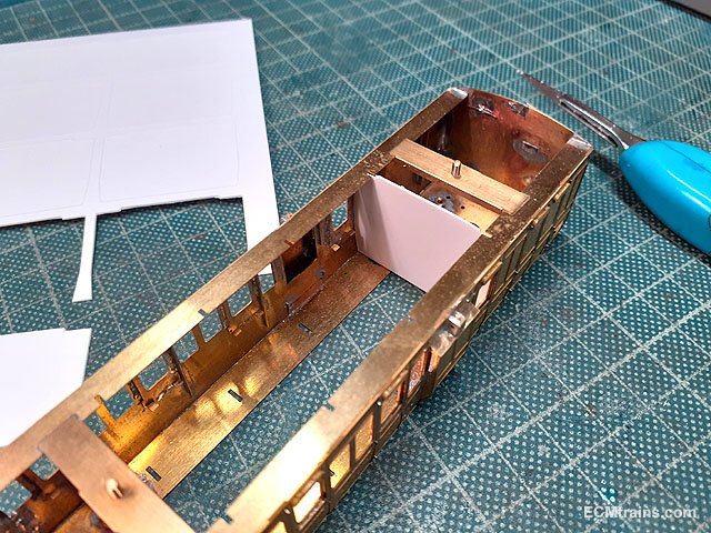
Cutting out the compartment partitions in .5mm styrene sheet.
Test fitted, I'm going to paint these separately and then glue them in. This will help with the coach internal wall painting and fitting the glazing.
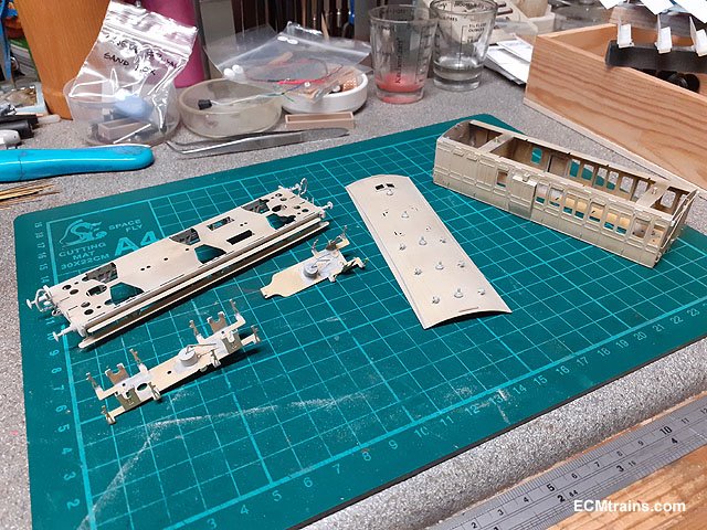
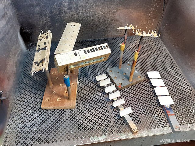
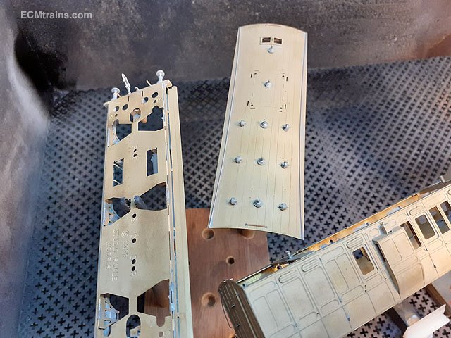
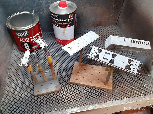
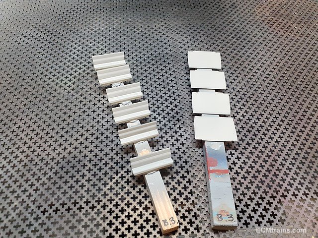
Fresh from the mini sandblaster.
Nice silky finish perfect for paint.....
......after a good wash though.
All washed with warm water water n washing soda.
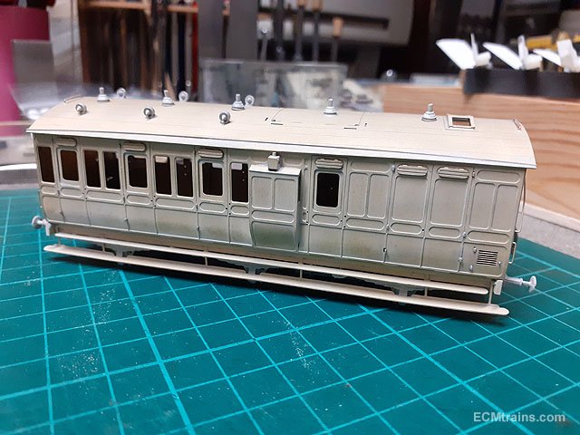
Etch primer applied, a very light coat, just enough so that one can still see the brass under.
Seats and partitions undercoated with grey enamel.
Just shown one of the 4 coaches, getting through it and colour will be next.......
Eoin.
-
9
-
-
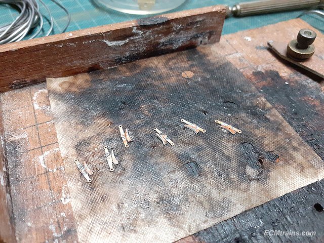
The tender spring clips/brackets- after studying a few photos of Merlin's tender I noticed the spring brackets are mounted above the springs with a gap between. The kit instructions suggest fitting the brackets directly on the springs, but it would look better and prototypical if a gap was provided!
I decided to epoxy glue the brackets to the tender outer frames as soldering would be impossible, I used one of the springs with .4mm styrene bits stuck on to act as a jig for placing the brackets. The brackets were folded up and the outer ends were curved downwards with a round nosed plires.
This is the jig set-up, its quite difficult to insert and position the brackets so the epoxy is going to be a bit messy. When the tender is painted and standing on the track one will never notice!
One side done.
Both sides done, the springs are propped up for this photo.....
Eoin
-
5
-
1
-
-
Excellent, it's all excellent.
Eoin
-
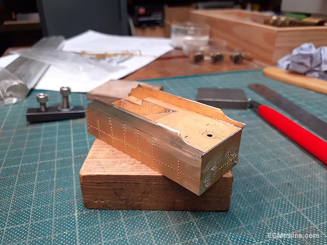
Continuing on with the Merlin tender;-
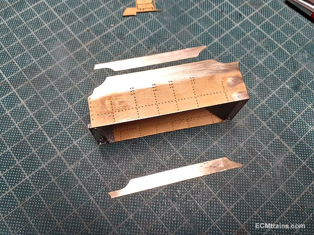
The upper side laminate parts are prepared for sweat soldering on.
Soldering is done with the help of Dinky clips to hold the laminate in place.
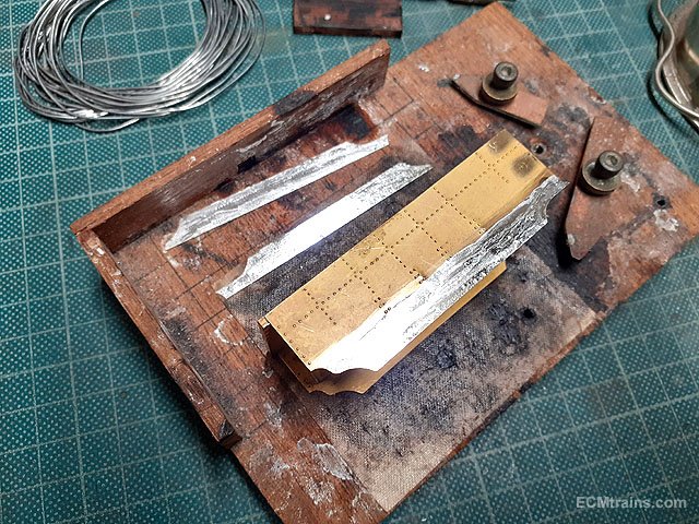
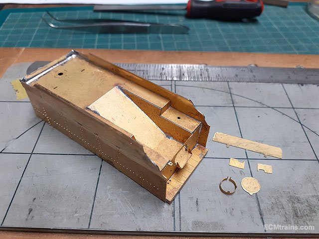
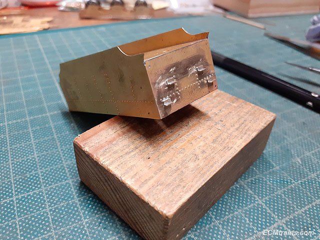
With the soldering cleaned up its time to put the top curve in the sides. This is the clamping arrangement with a 6mm dia bar and packing under the tender body to stop it slipping down while the brass is burnished over the 6mm bar.
Part way there, the burnishing was done with the ball end of that out of focus hammer on the bench in the background.
Curve complete and cleaned up- the burnishing left a few marks which were sorted out with files and emery paper.
The top back part was curved over the 6mm dia rod and soldered in place. Upper deck parts were prepared for soldering on.
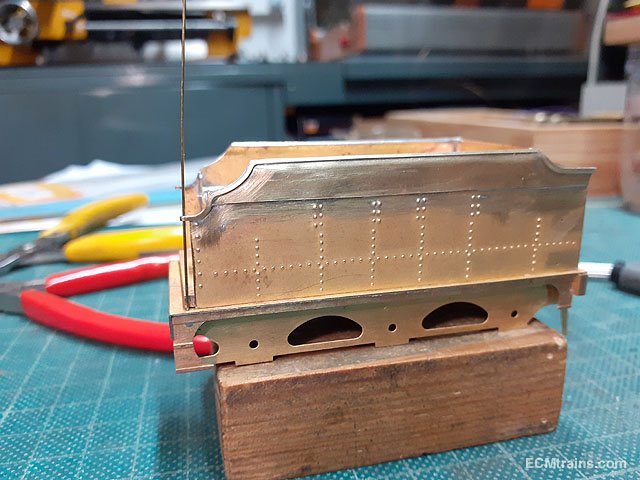
Edge beading to tender tops being soldered on.
Beading after clean up and now preparing the end loop to hold the handrails.
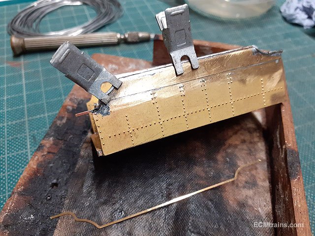
Water filler up-stand n cap, the coal sheet, and front tool box sheets soldered on. The coal sheet top corners had to be curved to fit the curved tender sides.
Next are the side steps and draw hook.
The steps are fiddly parts, with the aid of a Dinky clip to hold them the job worked OK except for burnt fingers! Dinkys are great because they are aluminium and the solder doesn't stick to them but they act as heat sinks- ouch!
Rear lamp brackets bent up and ready for sweat soldering on.
Hand brake and other handles prepared for fitting. The kit provides a white metal brake handle with a spigot for fixing, so I used a .8mm od brass tube for the riser with .5mm id to glue the handle into. The other rods are .4mm NS wire.
Handles soldered on.
That completes the tender assembly except for a few small items- the springs require clips to be soldered on, and the draw bar pin which I'm going to wait until the loco and tender are weighted and on the track to decide on the details......
Eoin
-
10
-
-
-
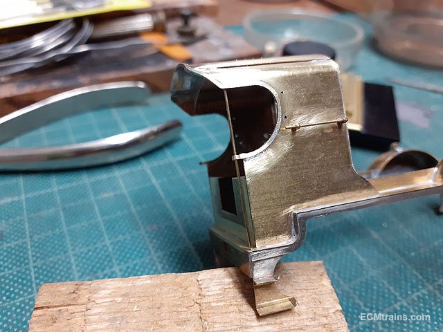
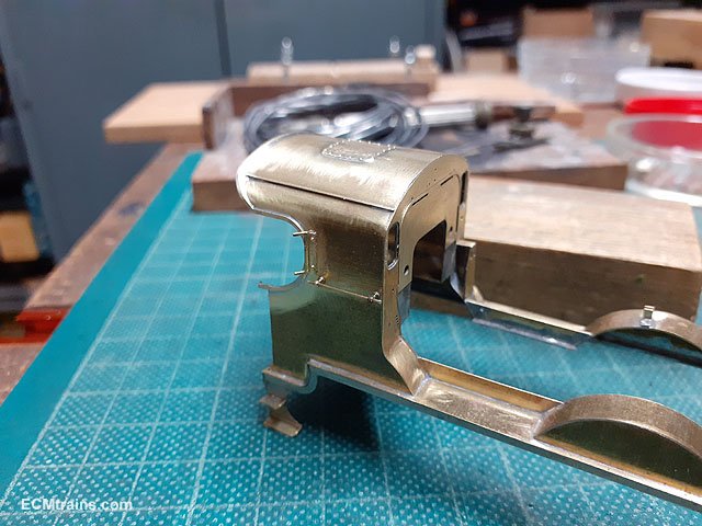
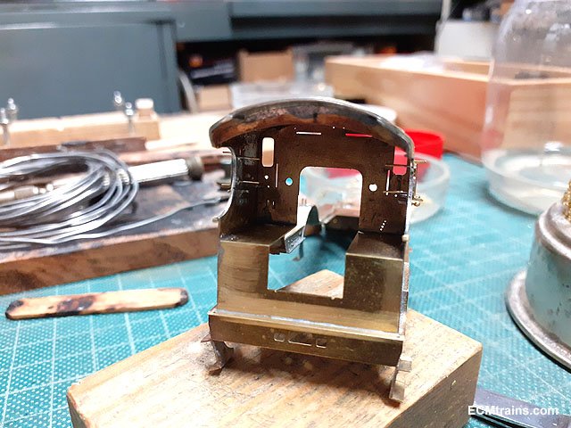
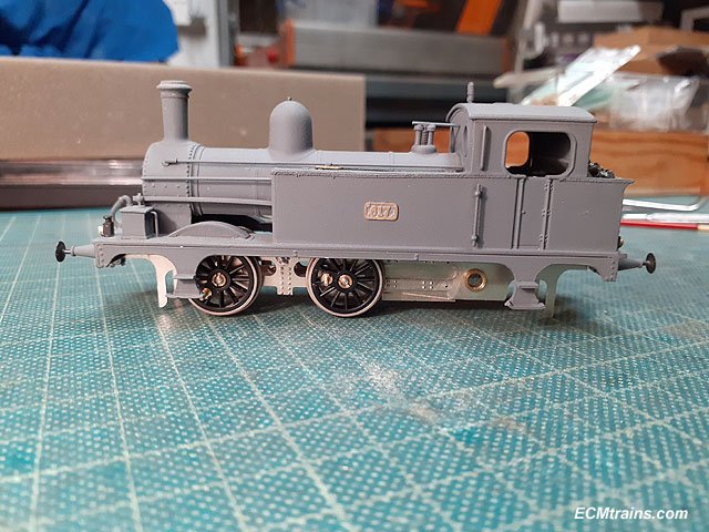
Cab parts are now finished on the J10;-
Parts cleaned up and ready for folding and soldering- cab front, side tanks, regulator handle, teapot shelf, and top gauges n steam cock stand.
Front plate and side tanks folded and soldered.
Assembly soldered to the cab floor after checking it all fits into the body. I'm not to worried about the wheels in the cab- they will be hard to see with the side tanks obscuring the view!
Backhead parts complete and test fitted, the backhead will be painted but I'm going to leave the fittings in brass finish.
Next step is paint.......
Eoin
-
7
-
 1
1
-
6
-
-
3 hours ago, murphaph said:
........Why does the flywheel need tapering Eoin? Just so it fits inside the body?
A flywheel works best with as much of it's overall weight running on the periphery, tapering out to the periphery does that- more weight on the outside gives more centrifugal force which smooths everything out.
Eoin
-
2
-
 3
3
-
-
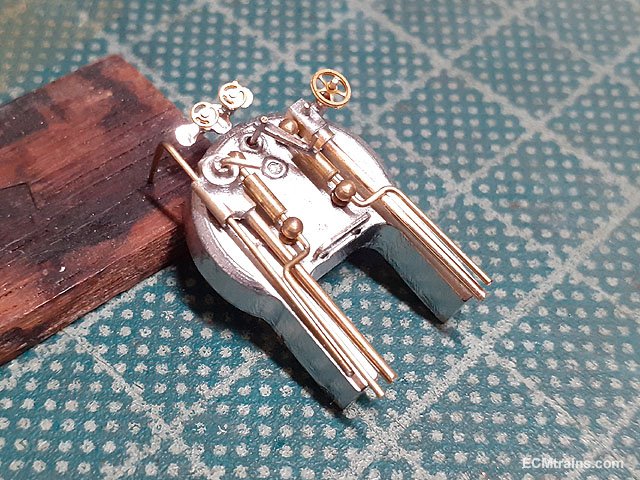
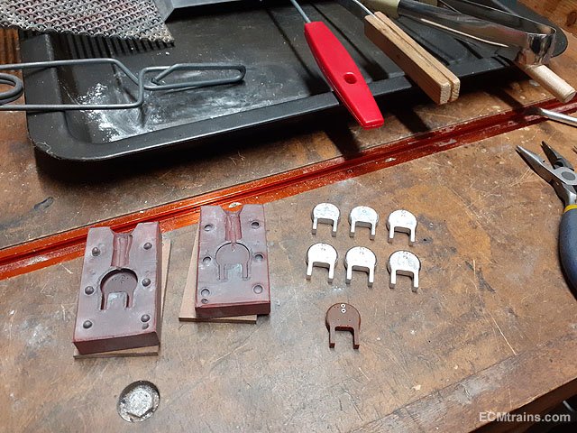
The backhead white metal casting mould was completed;-
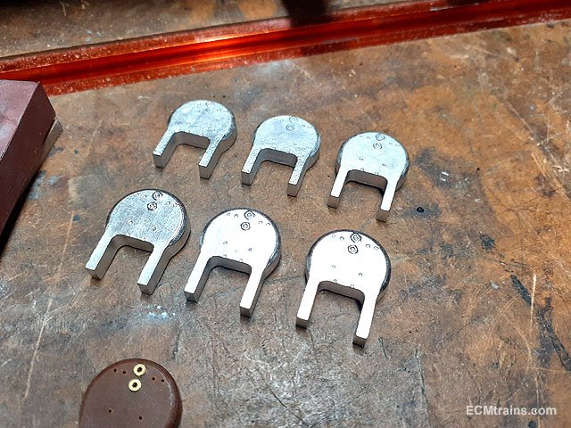
A few castings done.
The top 3 suffered a bit of chill in the mould, after making adjustments to the mould the bottom 3 came out nice n sharp.
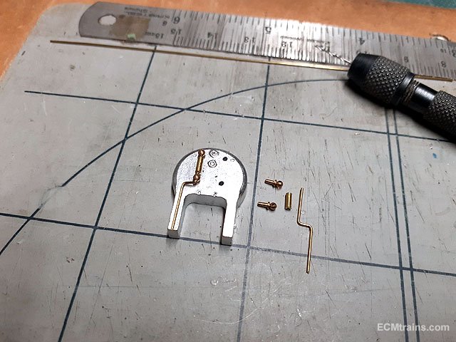
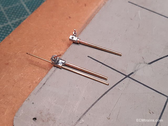
Setting up the water gauges, using handrail knobs, .5mm ID tube, and .5mm brass wire.
Setting up some steam equipment with brass box section, .5mm tube, .5mm and .8mm brass wire.
Soldered up.
Cab parts cut from .35mm NS sheet.
A bit of processing to be done..........
Eoin
-
7
-
3
-
-
You could be right on the name, I've not looked at this engine in about 10 years, it was Ken's post that reminded me.
Eoin
-
Hi Ken,
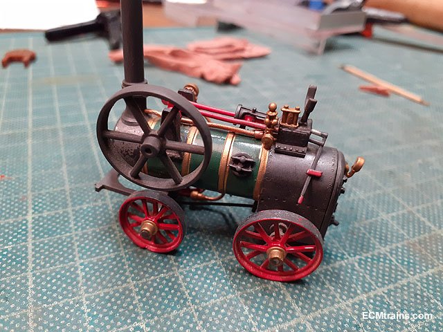
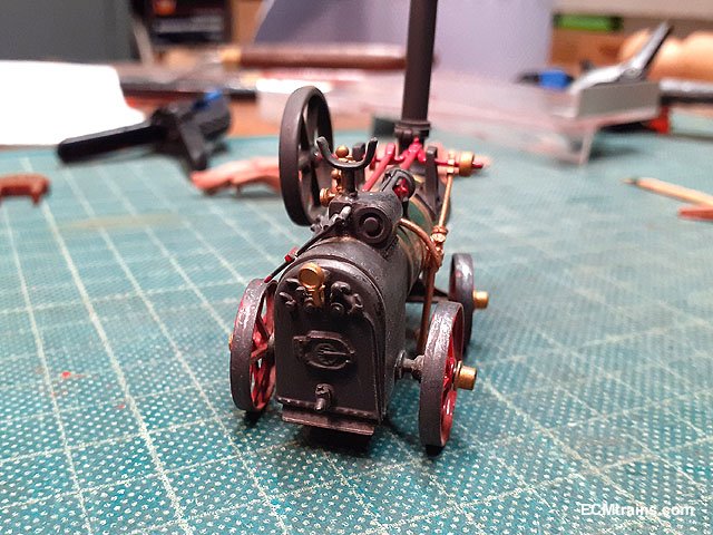
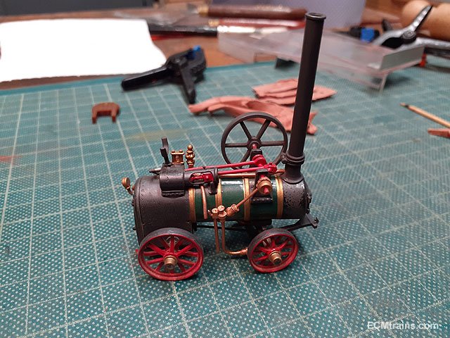
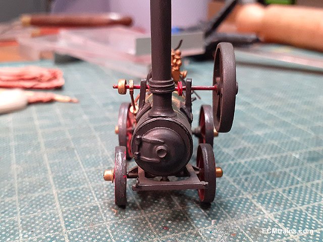
Looks like a Forrester engine, very nice....
I built a Forrester Mobile Engine many moons ago, its a white metal Langly track side kit.....
Some details may help!
Eoin
-
6
-
2
-
-
Hi ken,
Ernie Shepherd & Gerry Beesley's book 'Dublin & South Eastern Railway' notes on page 18 that-
They call it the 'Avoca Mineral Tramway' belonging to Mr Hodgson, it served the Ballymurtagh mine and the Ballygahan mine. The Hibernia Mine Company (inc 1792) held powers to Arklolw harbour and to construct a canal to Ovoca (seems it was called that also) but the canal was not built. The Wicklow Copper Mine Company (inc 1827) had people carry the ores to the harbour! The company opened the tramway around the famine time as the place de-populated, the gauge was 3'6'' and two wagons were drawn by horse initially.
In 1859 the authors note that the Company took possession of the tramway and rolling stock which had two locomotives and 100 wagons, Mr Hodgson was retained to run the tramway until 1861 when the DW&WR took over......
Eoin
-
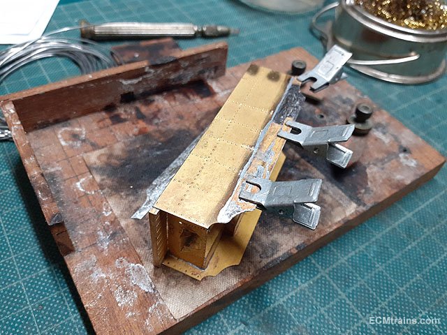
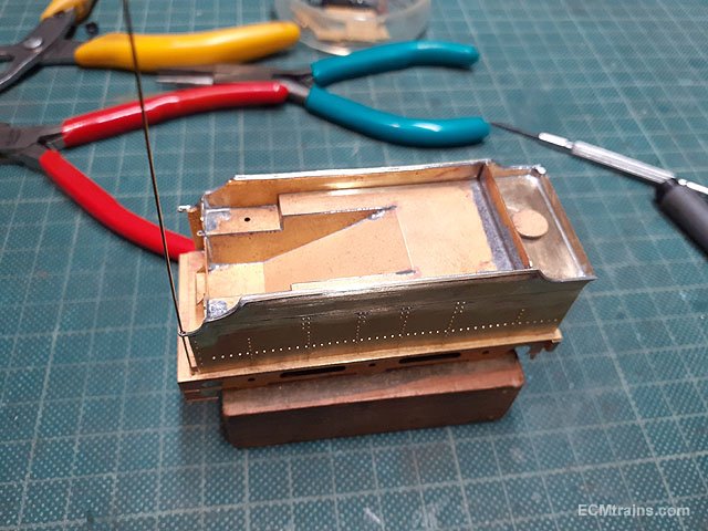
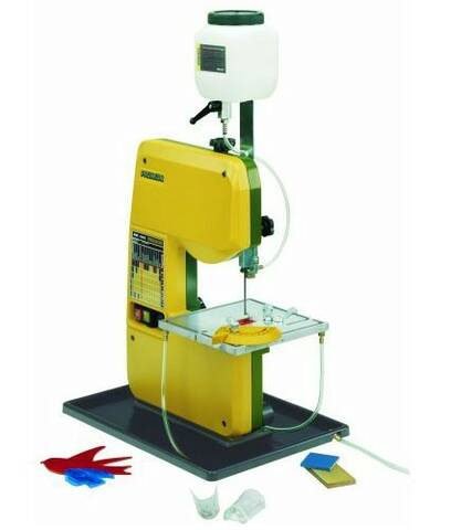
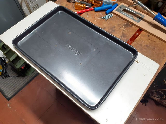
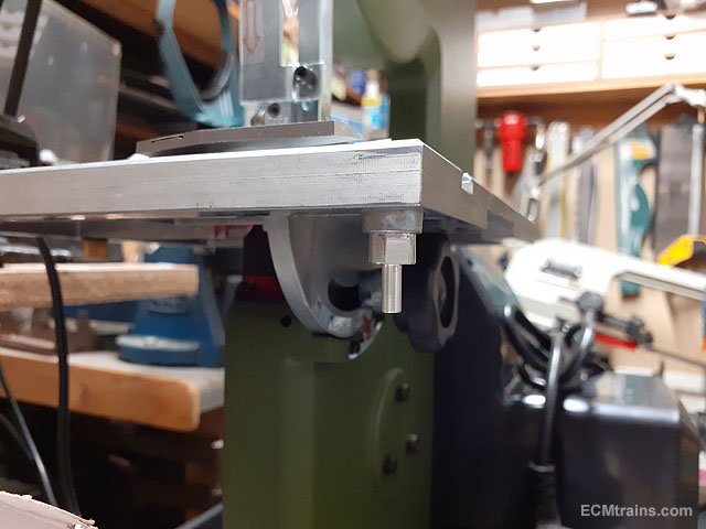
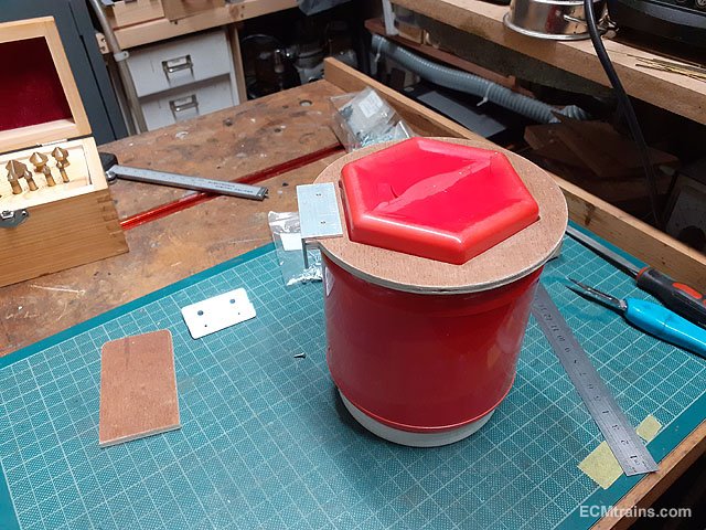
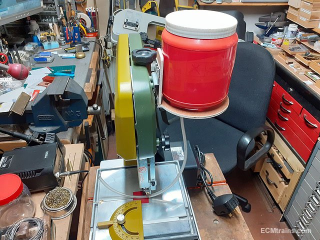
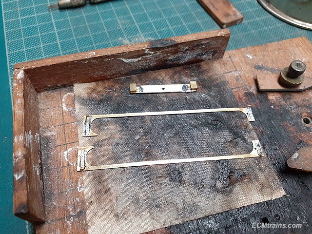
Proxxon MBS 240/E coolant upgrade;-
I bought one of these last year, mainly to cut metal, including steel. When buying it I found the coolant tank & tray optional extras are not available any-more! When cutting steel a coolant system is required if one wants the blade to last a reasonable amount of time.
So I had to make my own;-
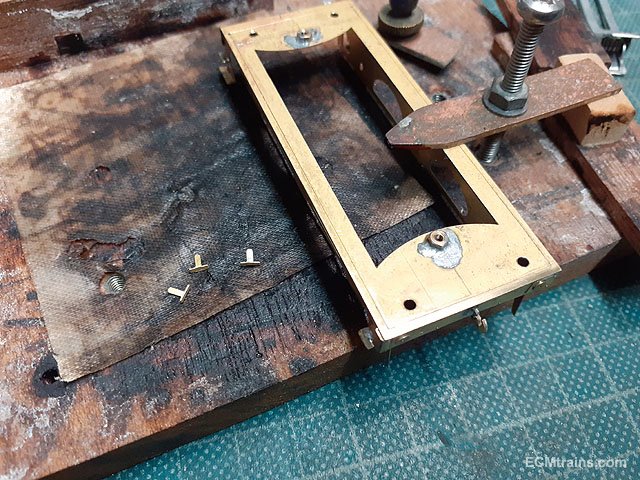
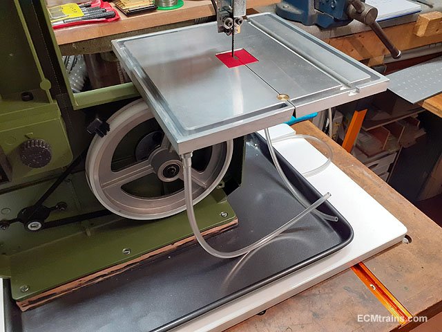
An oven tray of suitable size was found in Woodies, the tray was drilled mounted on a timber base with threaded inserts in the base.
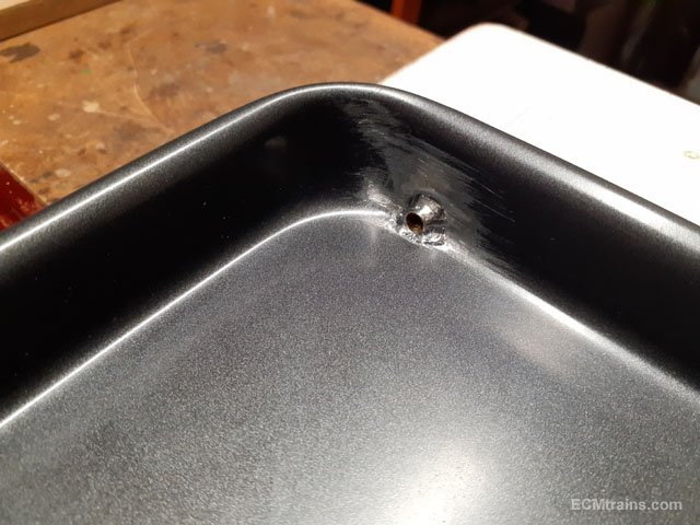
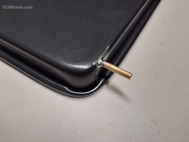
Drilled the tray and soldered in a brass pipe for the coolant drain.
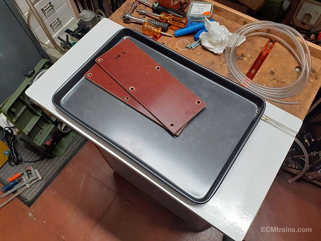
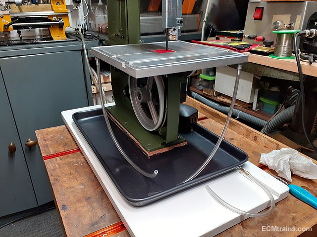
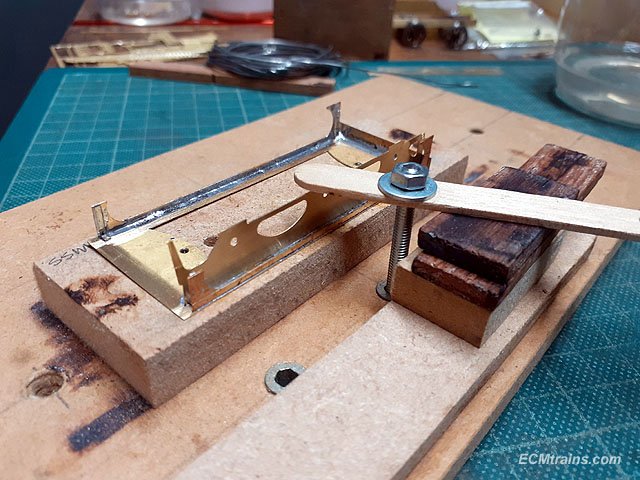
Two sheets of 10mm thick Tufnol were cut to form a riser under the saw and then the machine was bolted down. The tray outlet pipe just hangs over the edge of the timber base where a container will be hung to catch the coolant.
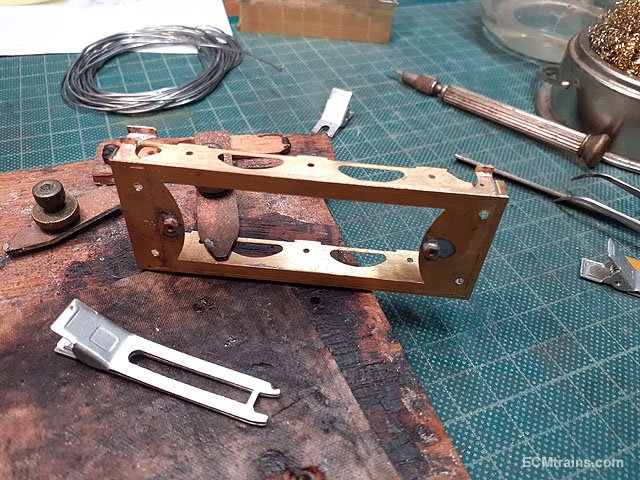
2 no. aluminium pipe connectors were turned up, threaded, and screwed into the table outlets.
Drain pipes installed.
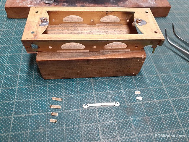
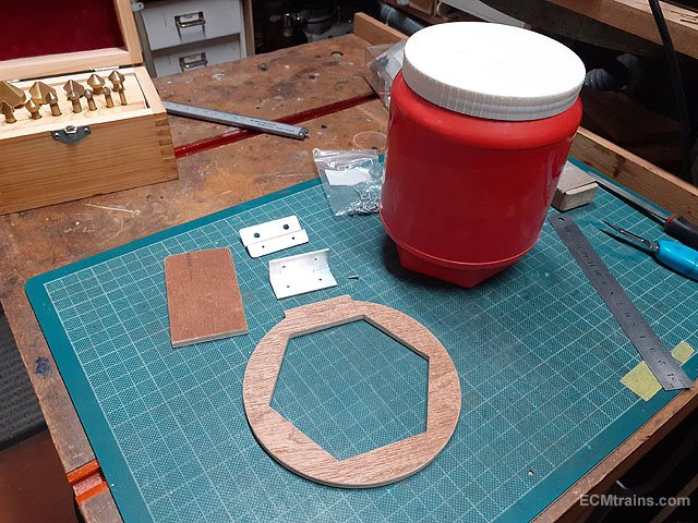
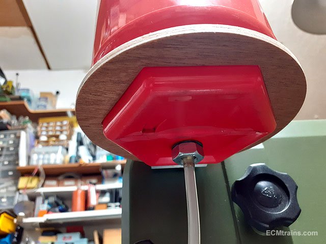
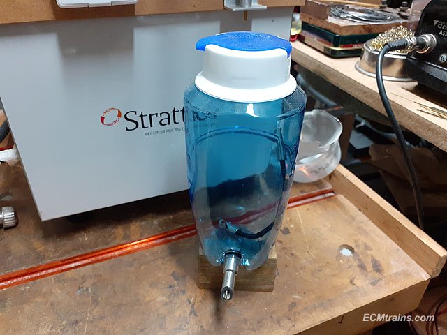
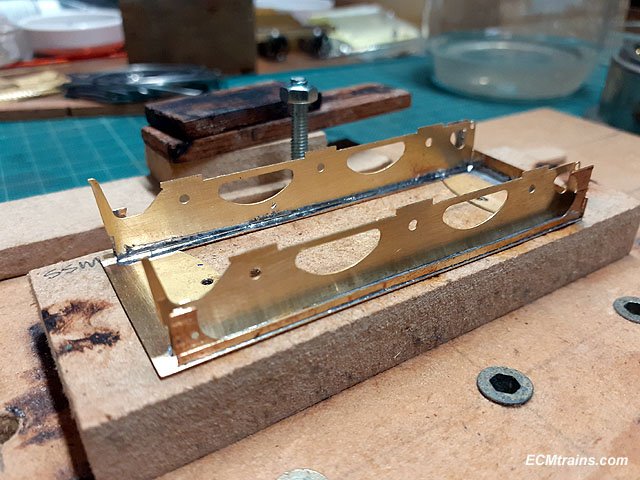
These are the parts for the coolant jar (an old Swarfega Tub), the plan is to be able to remove the jar easily, if not in use and for storing the machine away.
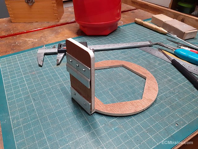
The jar sits in the bracket like this (upside down for the photo)
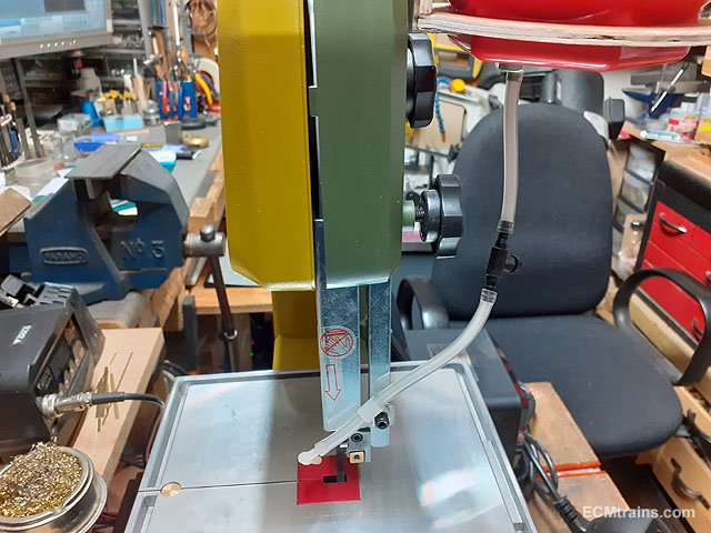
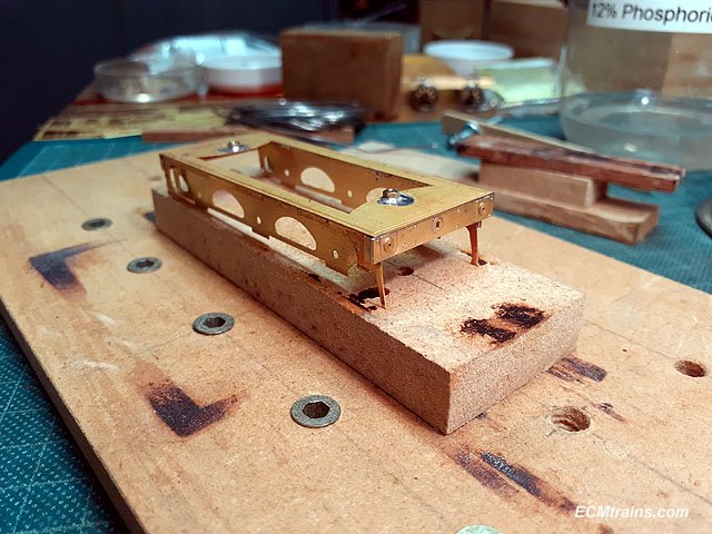
The bracket has a hanger strip on the back to hook onto a bracket fixed to the saw body.
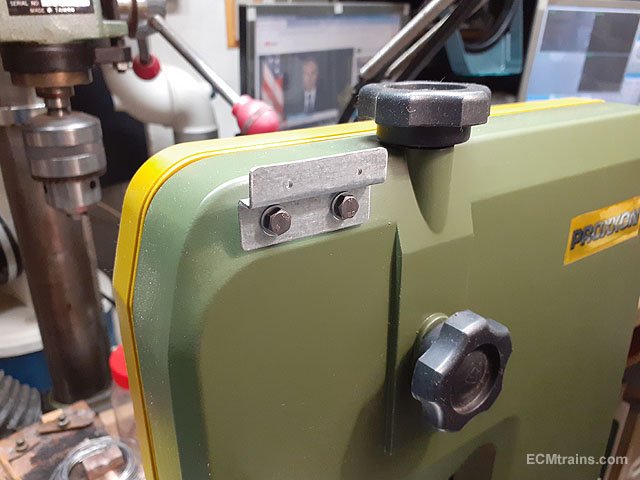
The bracket on the body.
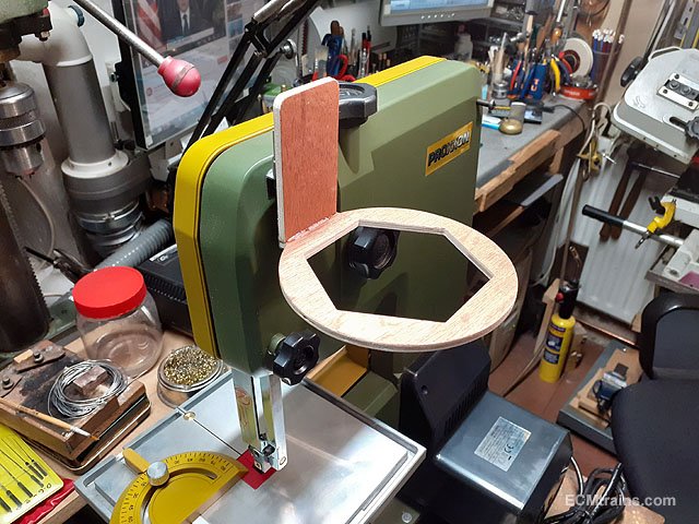
Hung!
The jar on, which will be glued to the bracket after painting.
The outlet is a brass fitting turned up and fitted to the jar using rubber washers to form a water seal.
Tap and 90 deg outlet fitted, the tap is an aquarium air pump tap!
I'm going to wait until I paint the plywood jar bracket before I test the setup, I shall post up a few photo when I do.........
Eoin
-
2
-
-
The March Fair date;-
-
3
-
-
7 minutes ago, Broithe said:
Nice - well worth doing - and, if it hadn't worked, you could have kept gerbils in it.
I am prepared......
-
2
-
-
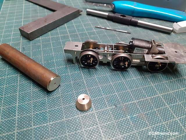
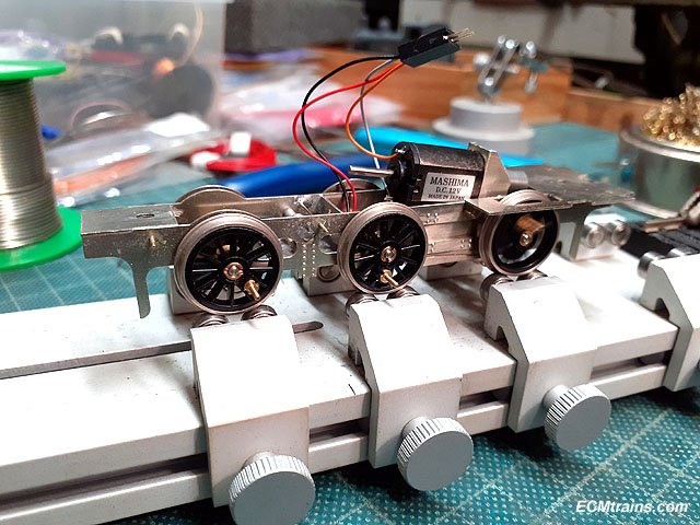
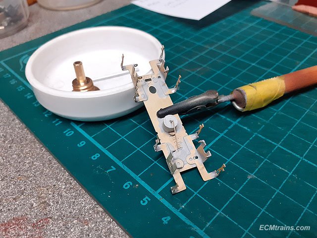
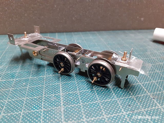
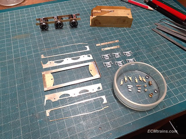
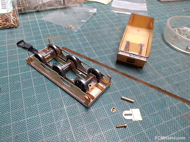
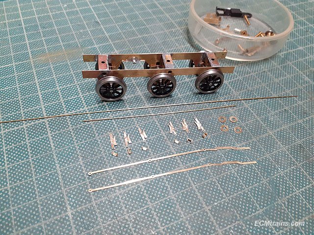
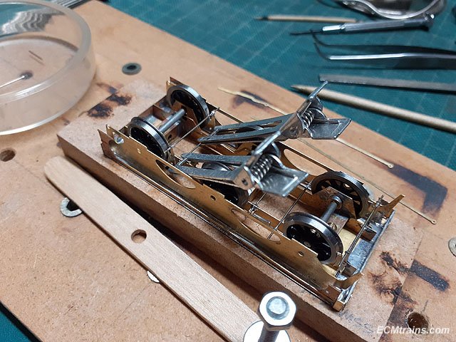
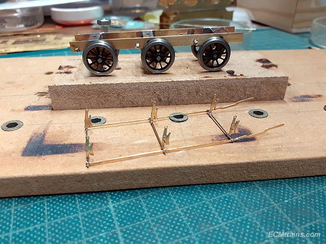
A few more bits done on the J10 chassis;-
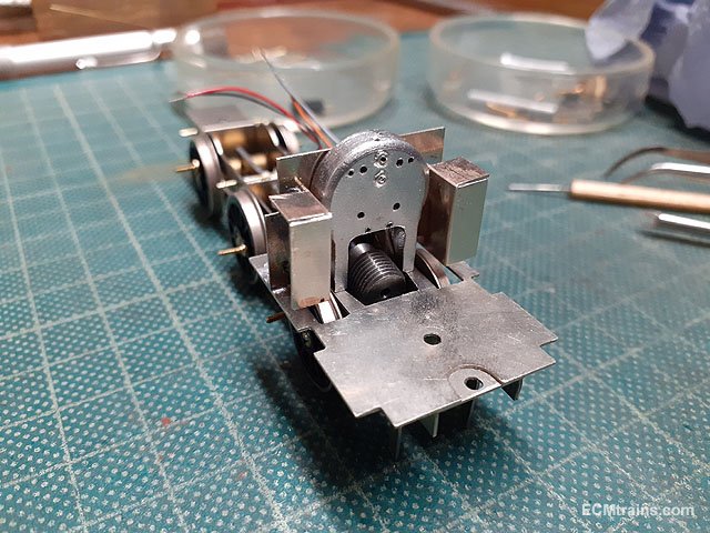
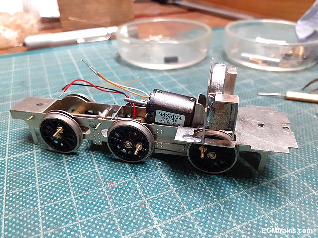
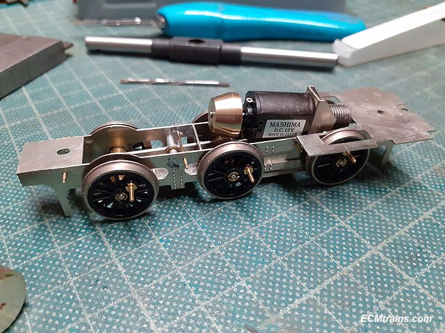
A tapered flywheel was turned up from a 12mm brass bar.
Flywheel test fitted.
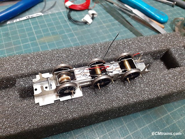
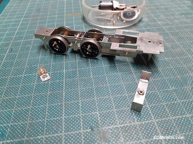
The electrical pickups .3mm NS wire were bent to shape and soldered in, electrical wires were soldered between the two pickup boards with tails threaded up through the chassis.
Testing the continuity of the pickups on the rolling road.
And first side of the backhead white metal mould done......
Eoin
-
5
-
-
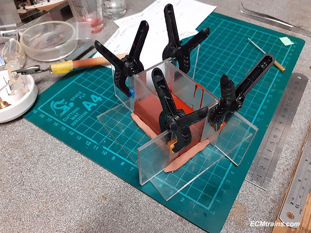
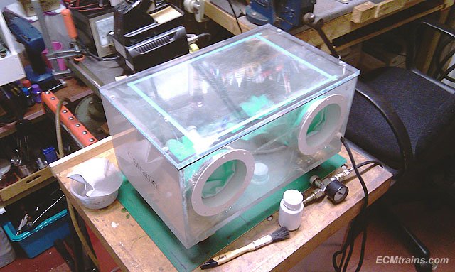
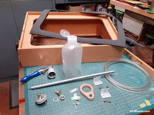
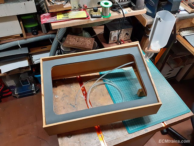
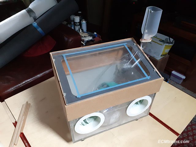
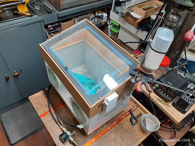
Mini Sandblasting Cabinet Upgrades;-
This cabinet was made a few years ago. It's made from a perspex medical display box, Woodies gloves, plumbing bits, and an Expo Tools airbrush sandblast gun. The gun, although it gives an excellent fine finish for painting, is a pain to use. The sand container lasts for about 20 seconds and then it has to be filled again- this works fine, but becomes a pain after about 6 goes. Also the cabinet is not tall enough internally and makes the work tight and uncomfortable.
So some upgrades are needed, as I have a bunch of 6 wheelers, a J10 chassis, and more coming along to paint. These models have a few delicate parts so I prefer to use this setup rather than my larger sandblaster which has a more aggressive grit which is prone to bend/warp delicate parts. Also this blaster has a very light cut, so light that paint can be cut back without going all the way through to the metal or plastic, it can also be used for weathering a model.
The work involved;- raising the lid, designing a sand hopper to feed the airbrush, and lights.
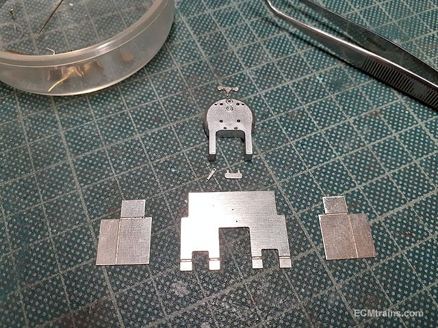
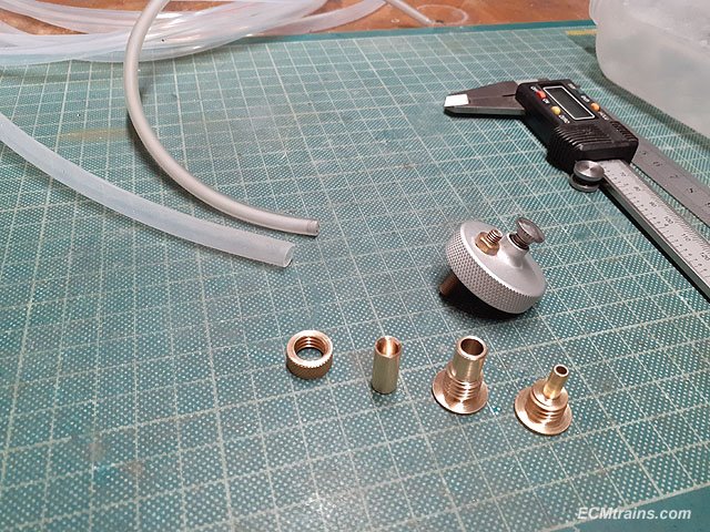
An MDF lid riser was constructed and all the parts needed made from brass and aluminium bar, aluminium sheet and angle, 4mm plastic tube, and a bit of ply wood.
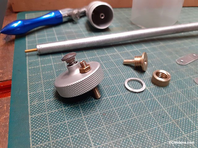
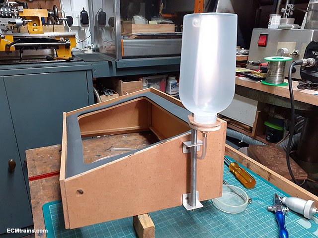
The airbrush sand hopper lid was modified by drilling and tapping an M4 hole and threading a tube through with lock nut to hold, the bore of the brass tube is 2.5mm dia. On the right in the photo is the sand outlet for the new hopper turned up in brass with a brass knurled nut.
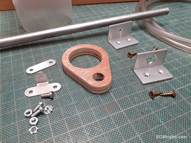
These are the bits to hold the new hopper.
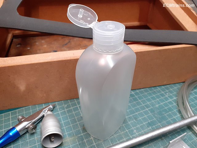
The new hopper is made from a Lidl hand-wash container.
Floor underlay foam was used to make a seal for the lid.
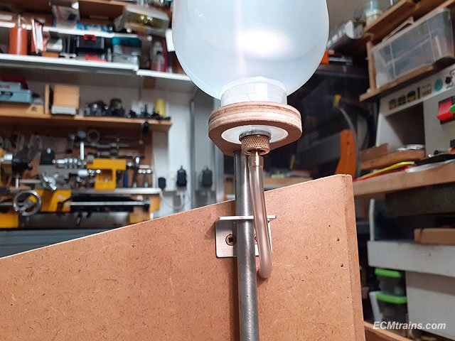
New hopper mounted.
This shows how the lid of the hand-wash bottle is modified to take the brass outlet.
Ready for testing.
Well things did not go well- the sand would not flow easily in the 4mm tube, and when the sand was used up in the tube the air would squirt up the tube and fire sand all over the place! So I decided two mods would be tried- a sealed hopper with a small air hole only and a larger diameter tube- 6mm.
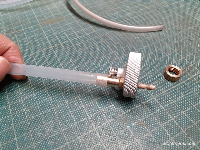
6mm diameter silicone tube was acquired and a few new brass fittings were turned up- a 6mm bore hopper out let (that's the old one on the right) and a brass fitting to connect the tube to the top of the airbrush.
The new fitting screws onto the brass M4 threaded tube on the lid and locks onto the nut.
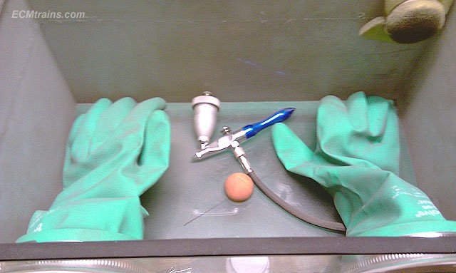
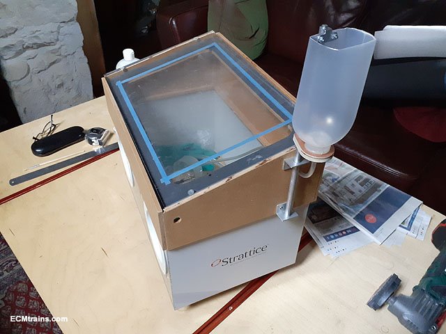
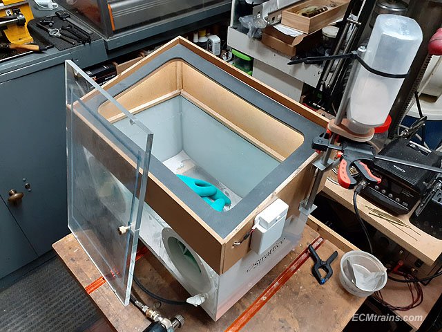
New sealed hopper bottle and LED strip lights (Lidl's best) installed.
The lid on and ready for a test. I still have to find a piano hinge for the lid!
The 6mm dia tube sorted the sand flow problem and I was able to blast the above 6 wheeler bogie part to a lovely silky finish in about 2 minutes. Blowback up the sand tube happens every so often, but pausing the blasting allows the sand to flow down again. Best thing is I could blast this part without having to refill the airbrush hopper every 20 seconds, I reckon a full bottle of sand should last for about 1.5 hours of blasting.
Some more tweaks will be done as I process more parts.......
Eoin
-
3
-
2
-
-
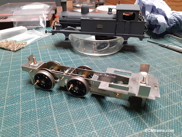
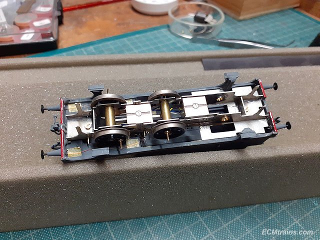
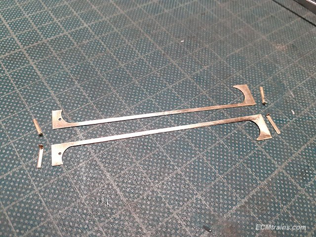
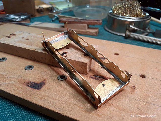
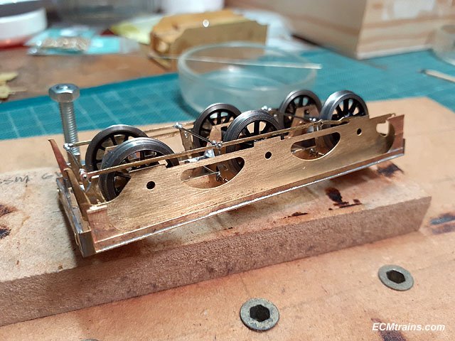
A bit more done on the J10 chassis conversion;-
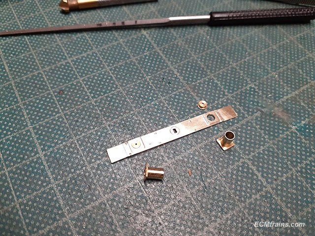
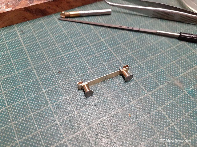
The cab footplate was soldered onto the chassis and the body fixing brackets were folded up and 10BA captive nuts soldered on.
Brackets fitted.
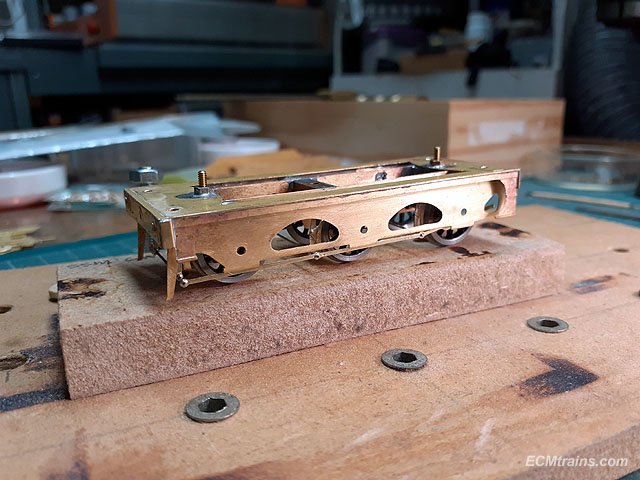
After scraping the inside of the body where the brackets will be epoxied on I decided to drill holes through the bracket tabs to aid the epoxy gripping the parts. The brackets are fixed to the chassis with some cling film between to stop the chassis getting stuck in the body also!
Chassis in place and bracket tabs epoxied to the body.
Brackets glued in.
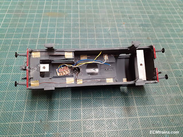
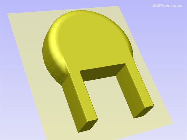
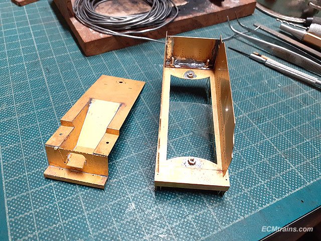
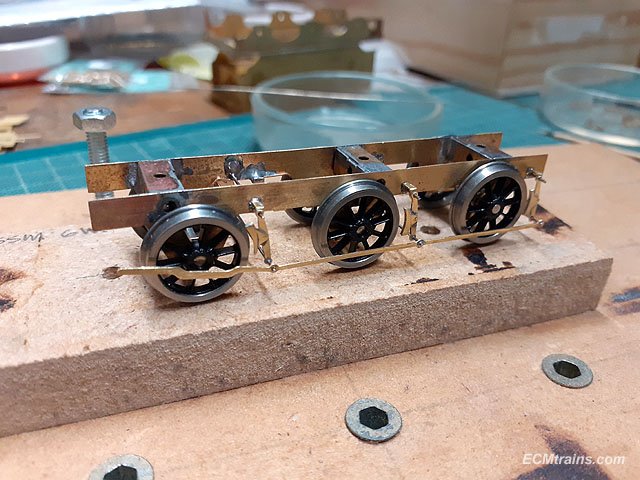
Next was to set up some cab details, a cab front plate , a backhead, and the cab side tanks were worked out.
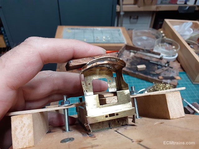
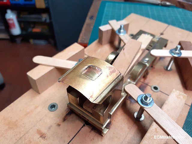
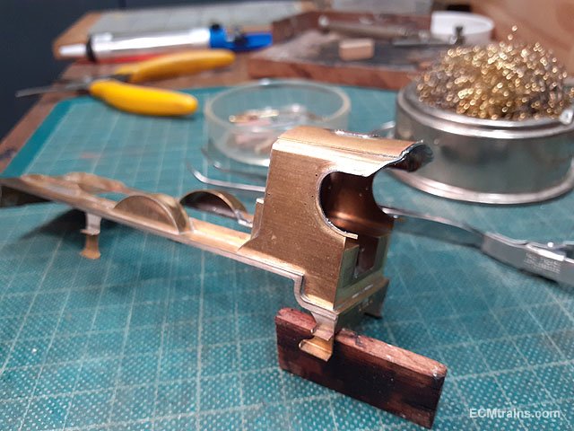
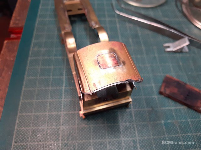
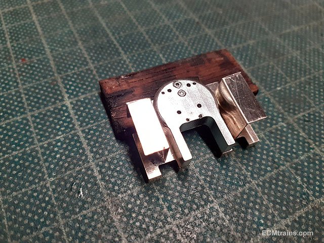
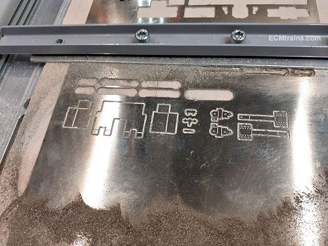
This is a screen capture of the backhead model set up for CNC'ing from a sheet of tufnol. The big gap is for the motor gearbox which protrudes into the cab.
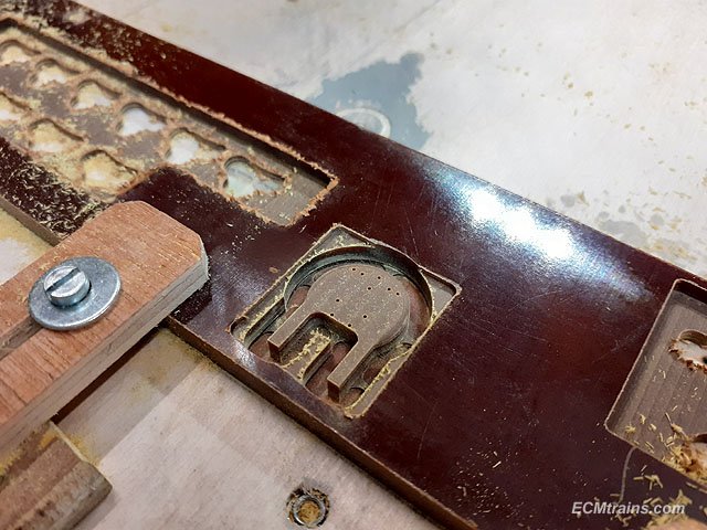
The backhead cut from a 5mm thick sheet, the part is 4mm thick.
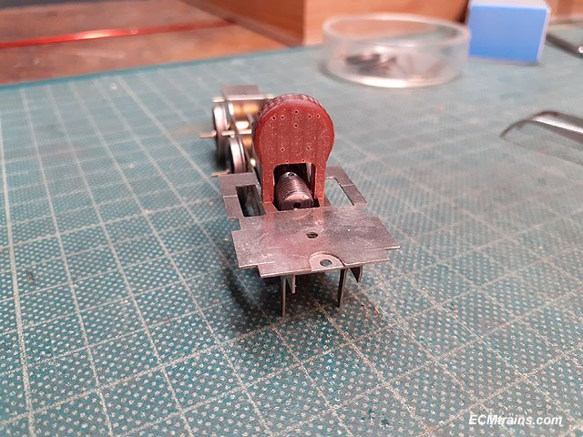
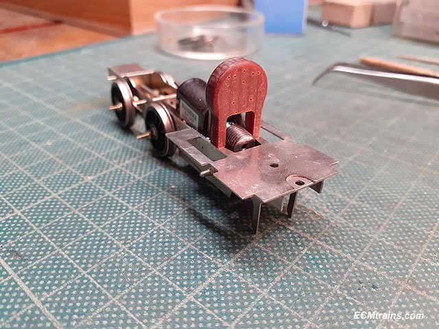
Cleaned up and test fitted over the gearbox. Some details will be fitted- these parts are included for, when the front plate and tank parts are being cut. I'm also going to make a mould from this so that the backhead will be cast with white metal, adding weight to the loco......
Eoin.
-
14
-
-
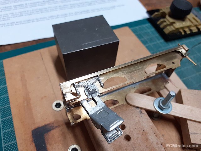
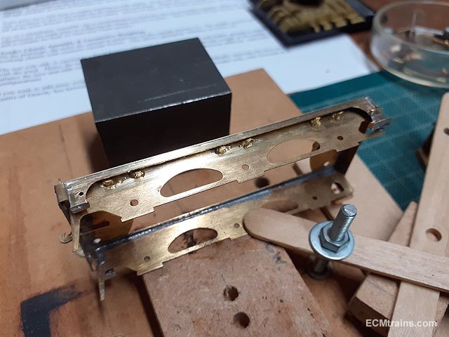
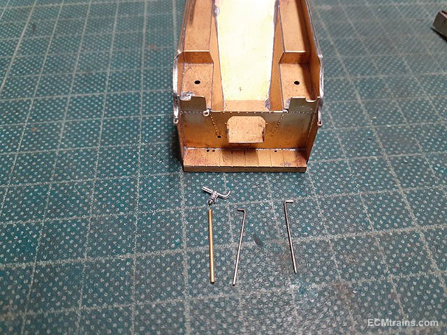
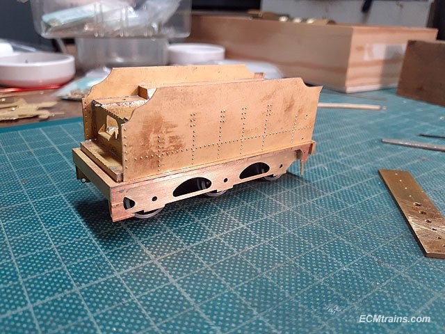
Carrying on with the tender;-
Valances, frames, steps, brake parts, buffers and axle springs were cut out and cleaned up. The springs will be fixed on after painting.
The valance step parts will be reinforced with a brass strip behind.
Buffer shanks had the end bead filed off and the buffer beam holes opened up to take the buffer furls.
Buffer test assembled.
Valance reinforcing strips and buffer furls soldered on.
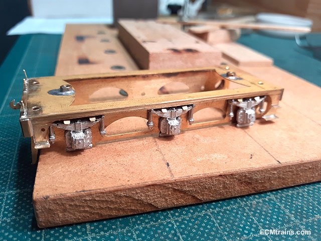
Soldering the valance to the tender running plate.
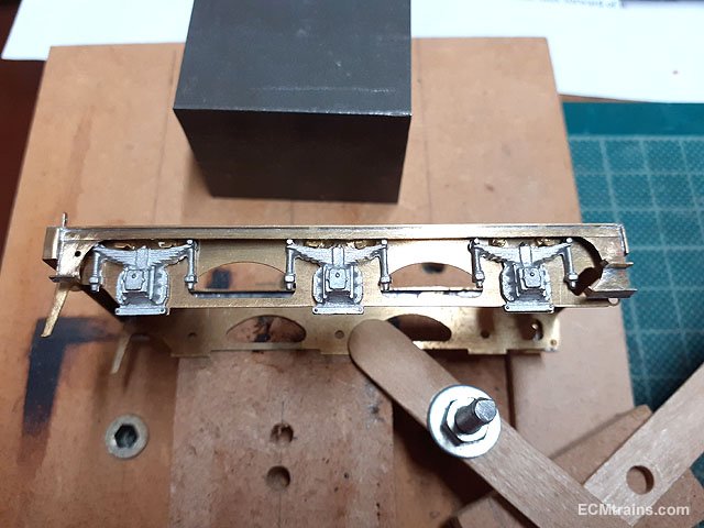
Inner frames being soldered on.
Done.
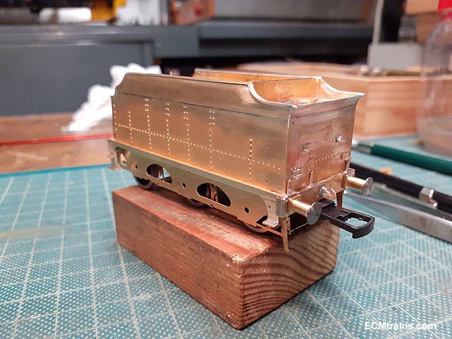
Buffer beam soldered on.
Working out the drag bar and tender rear coupler. The instructions and the kit goes a bit wrong here- the instructions reference the draw bar part no. 1, but there is no such part in the kit! There are extra tender parts in the kit and one of these can be used for the drag bar, it's part no. 87, some mods will be needed but it should work. The coupler is a Dapol type, which will need mods also.
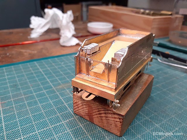
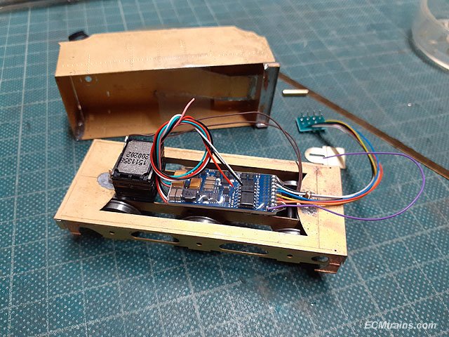
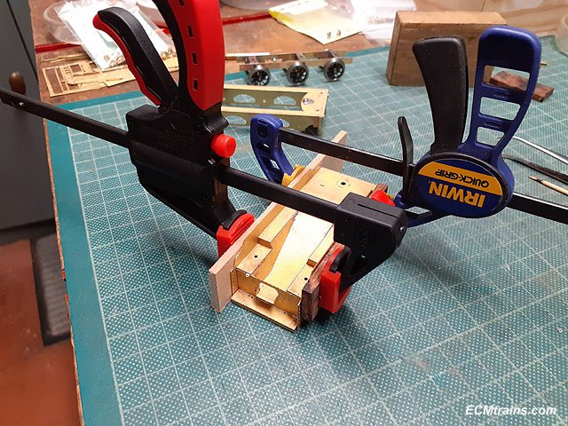
After that was worked out next was to decide how to mount the DCC chip and speaker, also a plan for access to the chip & speaker in the future. So it was decided that the best solution is the have the upper tender body removable from the running plate. This will need a few holes drilled in the running plate, screws and captive nuts to be installed!
The rear captive 10BA nuts installed on a brass strap soldered to the upper body and screw fixed to the running plate.
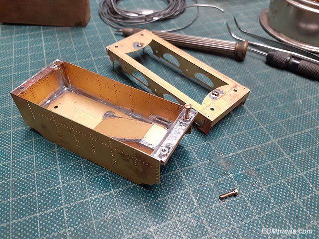
With the rear nuts soldered in the upper deck of the tender is now soldered on.
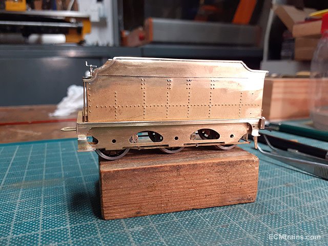
Then after drilling holes in the front of the running plate, position for captive nuts are marked up and nuts soldered on the underside of the tender step.
After the 10BA screws are sized the parts were bolted together.
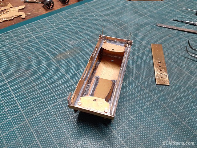
All fits nicely after slight adjustment to the screw holes in the running plate. This will also be handy for painting.
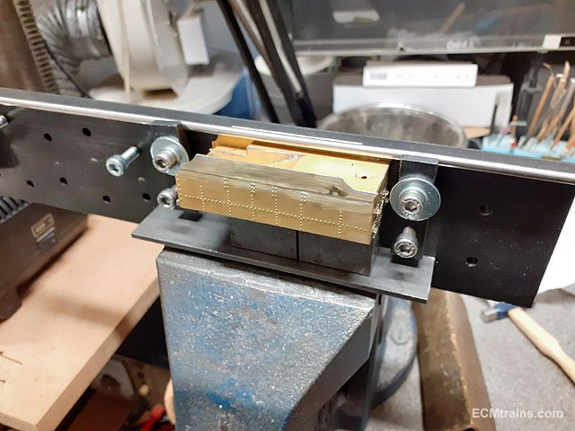
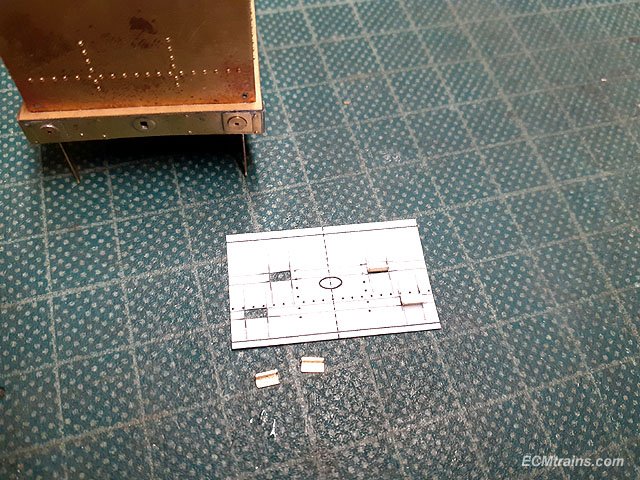
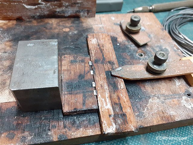
Next is the tender body rear steps, these were scratch made from fret offcuts as these steps are on the prototype but not in the kit. A soldering position guide was made from the drawing used for the rivet embossing, holes are cut out for the steps.
Solder being applied to the back of the steps.
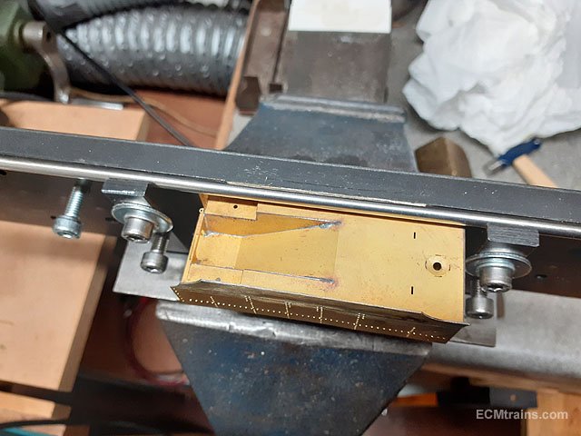
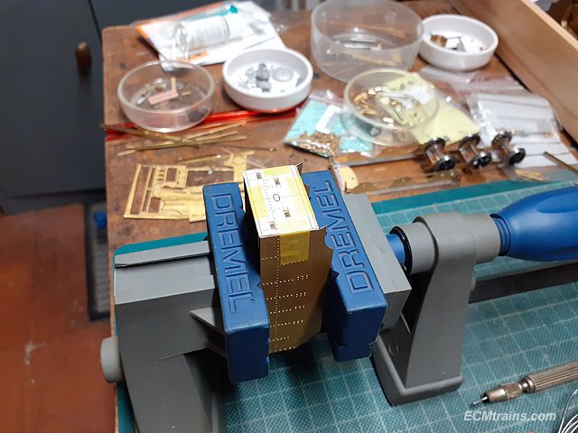
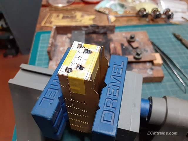
The guide was taped to the tender body held in a vice.
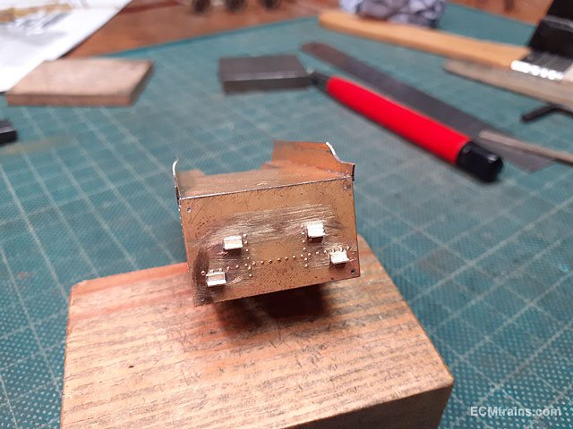
Soldered.
Cleaned up.
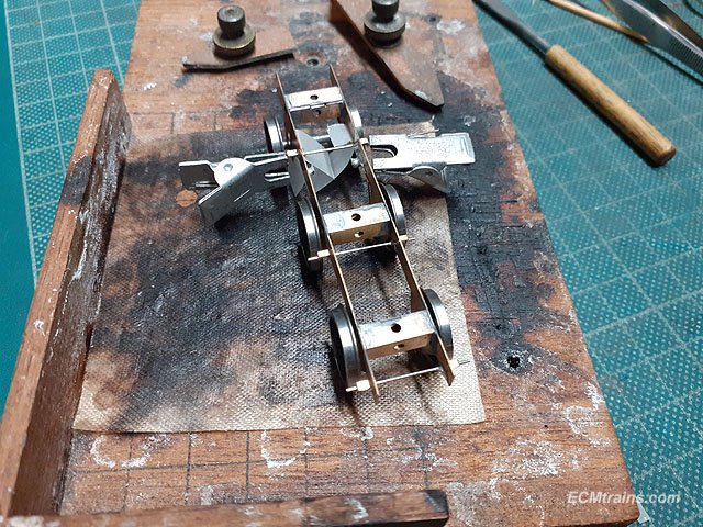
Next the brakes n rods, brake shoe parts were sweat soldered onto the hangers.
All cleaned up and ready to fit.
First the .5mm NS chassis cross wires were soldered on, with the hanger spacers on so that the solder wicks through the hole and grabs them too. Bits of tracing paper was installed behind the front axle springs because the cross wire is right on top of the spring and we don't want the springs soldered!
Then the hangers and the lower cross wires are fitted, only the lower cross wires are soldered to the bottom of the hangers. The upper hole of the hangers are left dry so that the brake gear can be removed.
The pull rods were then installed outside of the wheels.
Brakes complete.
Running plate removed.
Brake assembly removed.
Eoin.
-
5
-

.jpg.e1d8d9e7ba170da761aec6022ed344f9.jpg)

GNRi Class V Merlin Gauge OO Build
in ECM Model Trains
Posted
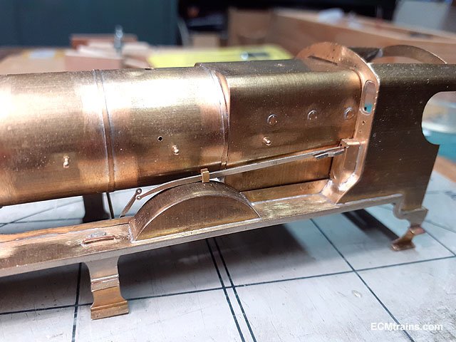
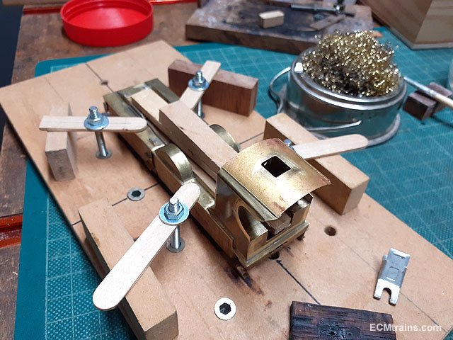
Onto the loco lights and cab detail stuff;-
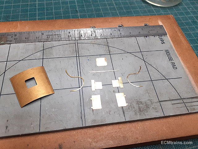
Warm white micro LEDs, 10k resistors and Springside white metal loco lamps.
Drilling out the lamps with .8mm for the lens and 1.2mm to underside for fitting the LEDs in.
Drilled.
I Inserted an LED to test under power to find the LEDs are not warm white, but yellow! Also the 10k resistor needed to be upped to bring the LED intensity down. I settled on a 5 ohm resistor as the best, which is what's running the LED in the above photo. Warm white is now on order!
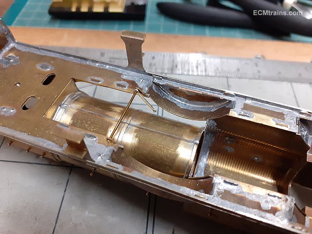
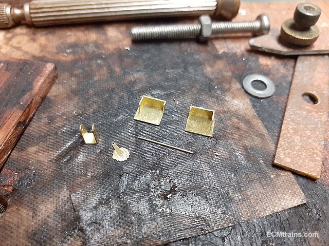
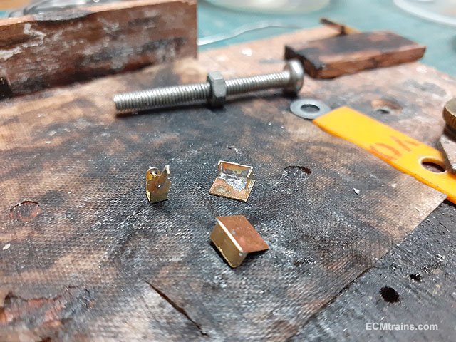
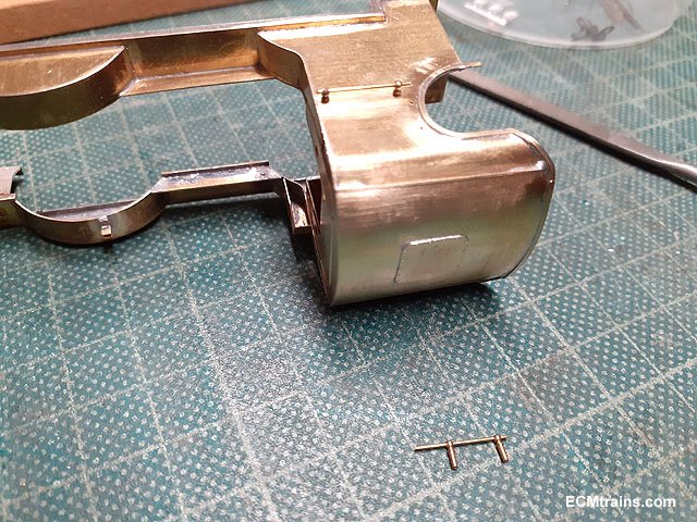
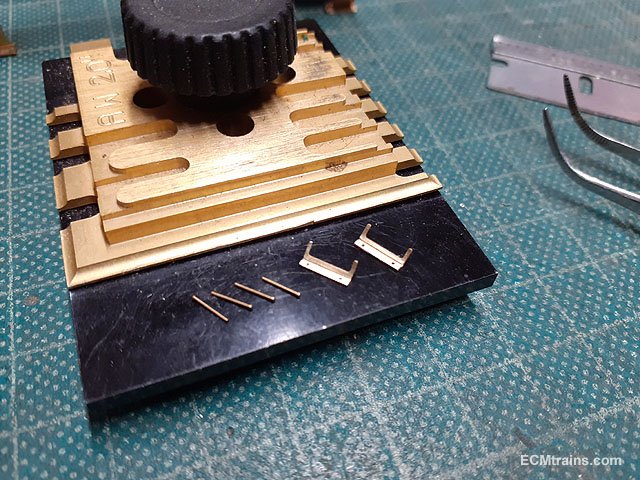
The kit does not provide a vacuum ejector so I setup a few bits for one- from 1.5mm square brass box, a 14BA screw, .3mm pb wire bent up for the operating handle, and a brass strip to finish the body of the ejector and to fix the assembly to the backhead.
Vacuum ejector and pipework setup for soldering.
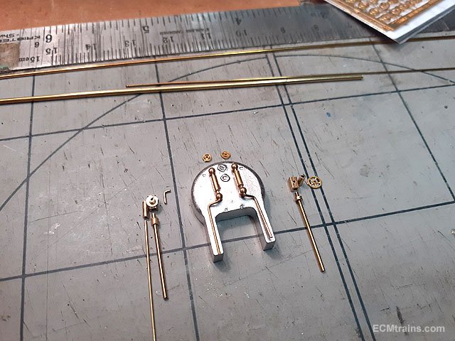
Combination injectors, water gauges, regulator handle, hand wheels, and pipe work prepared for the backhead. The pipes are .8mm & .4mm copper wire. The combination injectors will be fixed to the backhead now, the remainder will be fixed after the backhead is painted.
Eoin