

murrayec
-
Posts
2,570 -
Joined
-
Last visited
-
Days Won
67
Content Type
Profiles
Forums
Resource Library
Events
Gallery
Blogs
Store
Community Map
Posts posted by murrayec
-
-
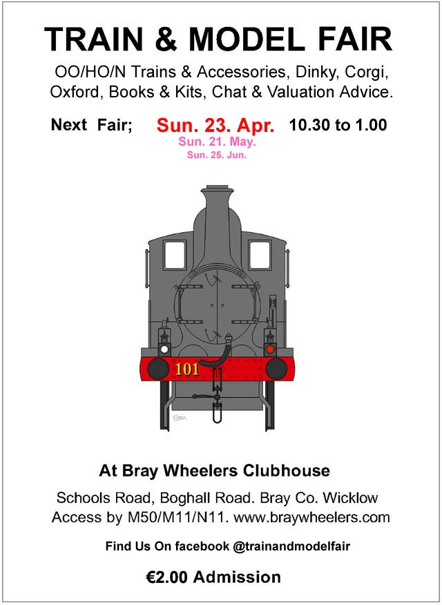
April Fair Date;-

-
 4
4
-
 1
1
-
-
The Great Sugar Loaf yesterday;-
Eoin.
-
1
-
-
@FiacraA few photo of the motor mounting would help?
If the motor is mounted directly under the points this could restrict movement as the actuation rod is short and cannot bend for short point movement! So if the motor is mounted with, say a 20mm thick mdf spacer between the motor and point, this would allow the actuating rod to bend a bit and allow the switch to operate correctly??
Eoin.
-
2
-
-
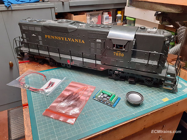
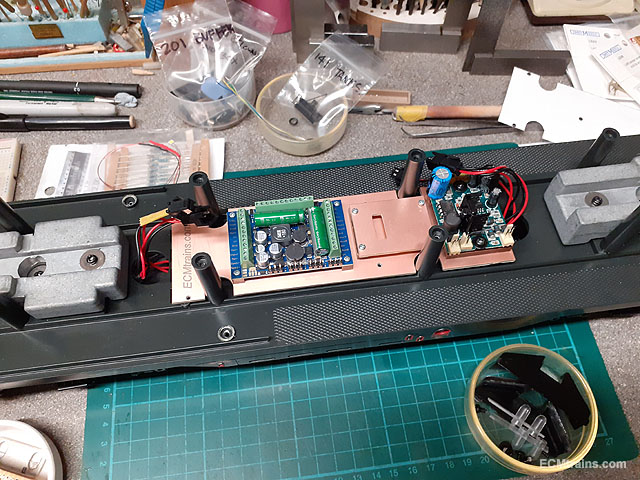
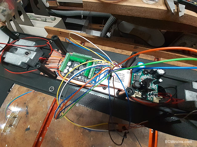
This is a garden railway analogue GP9 loco with lights and 2 smoke generators. The client wanted to upgrade to DCC, so here we go.......
An ESU 5XL DCC sound board was chosen as it has the power for 4 motors, two in each bogie, and a bunch of aux outputs for this upgrade and anything added later. An 8ohm speaker, LED directional lights and LED cab light.
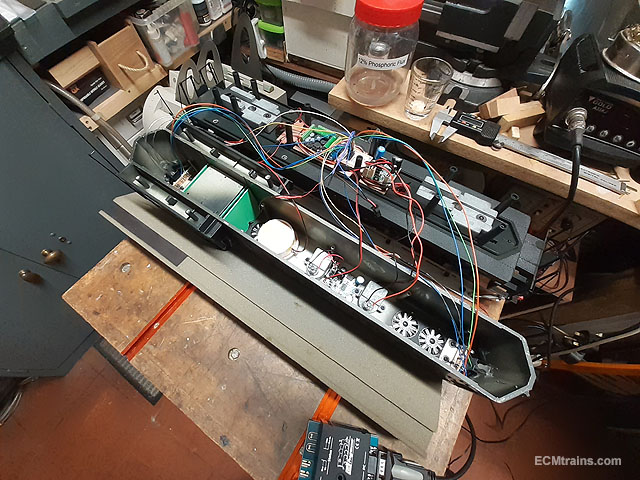
A look at the analogue system, the main board is mounted on the chassis with a number of switches underneath to set the functions, with two analogue smoke generator boards- one mounted beside the main board and the other under the hood.
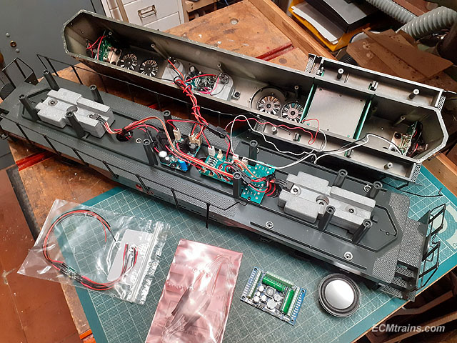
So after some consideration on how to tackle this I came up with a plan.....
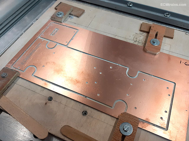
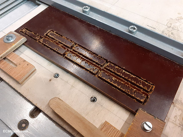
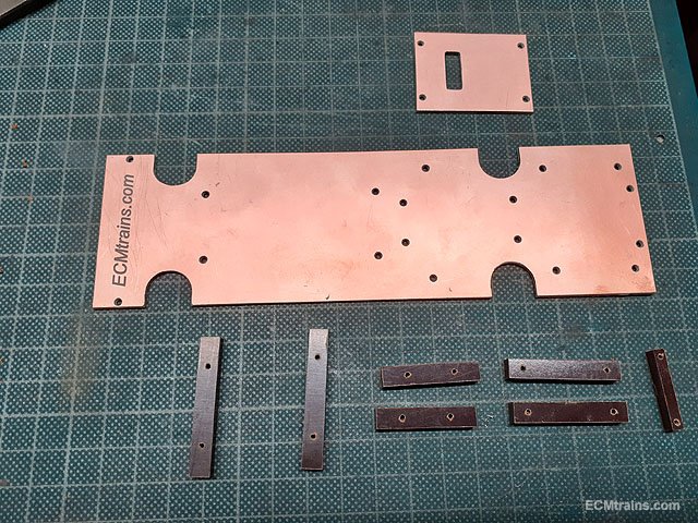
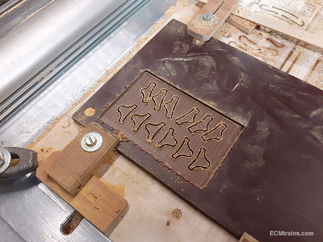
Cutting out a PCB mounting board for the DCC chip and one of the smoke generators, the small board is for mounting a wiring socket.
Riser blocks being cut from 10mm Tufnol sheet for mounting the PCB board to the chassis and risers for mounting the new control boards.
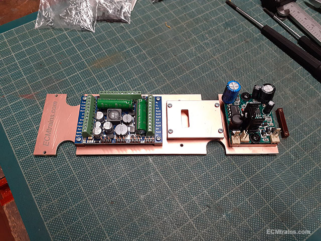
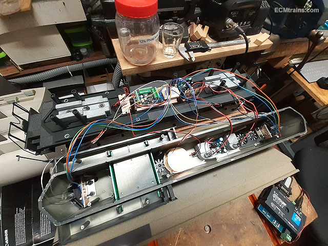
Boards mounted.
And the lot screwed onto the chassis, I used the old mounting lugs on the chassis to screw it down.
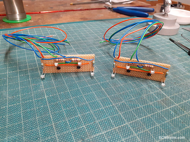
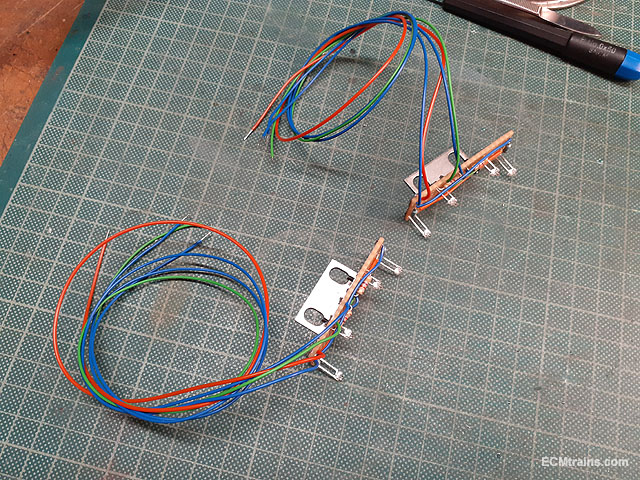
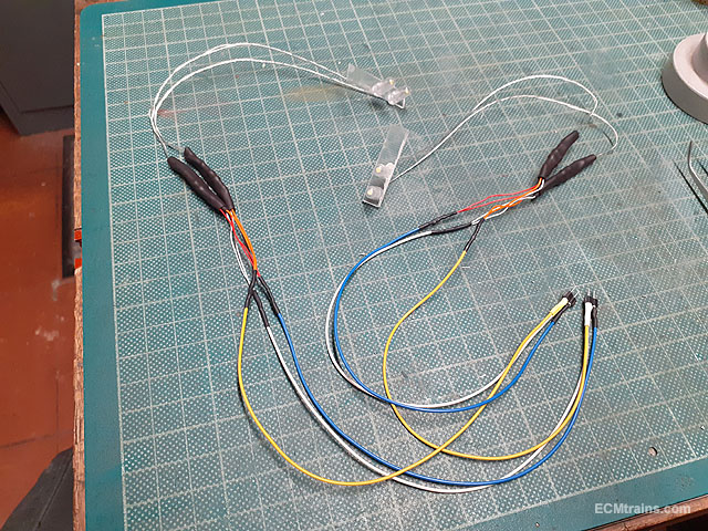
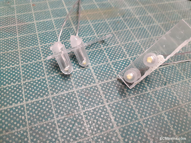
Replacement LED code and side light boards.
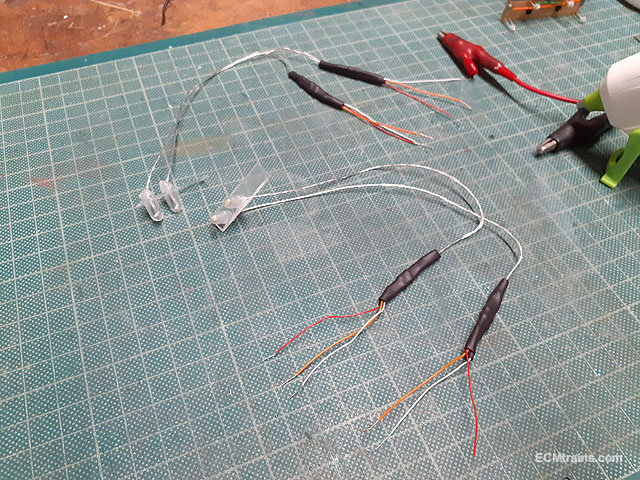
Directional LED head lights being setup.
The LEDs are hot glued into the original front light housings.
A LED cab light was also installed but no photos as to how that was done!
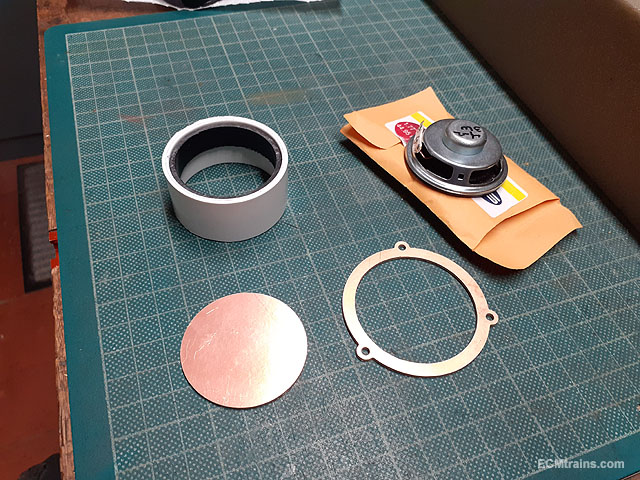
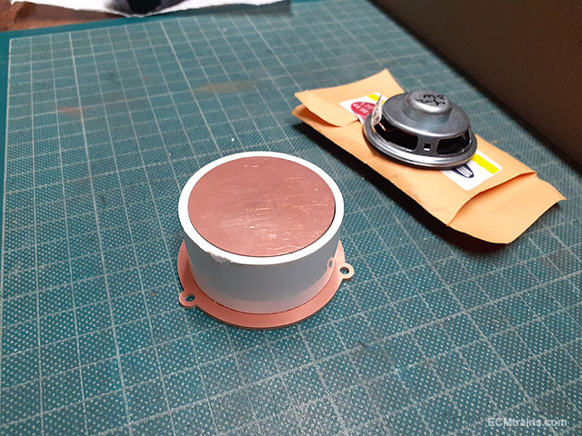
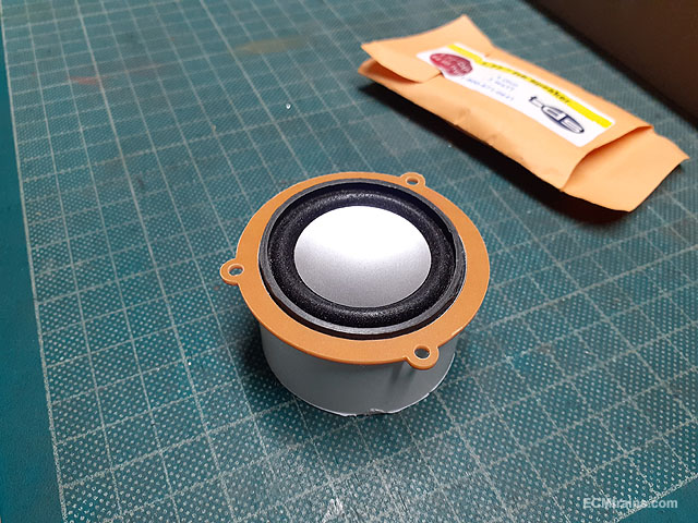
The speaker enclosure being setup, made from some PVC waste pipe and PCB parts CNC cut to mount and close the back after the speaker is installed. when the speaker is wired up the whole will be epoxied together.
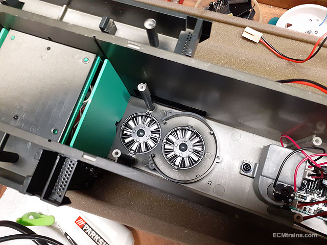
The enclosure will be screw mounted onto the 3 lugs around the fan.
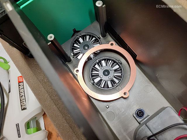
To make this part a paper impression was taken from the screw lugs on the fan, this was scanned into cad, a drawing setup and then the part was cut out on the cnc machine.
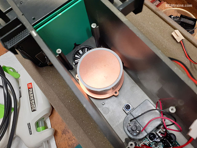
It fitted!!
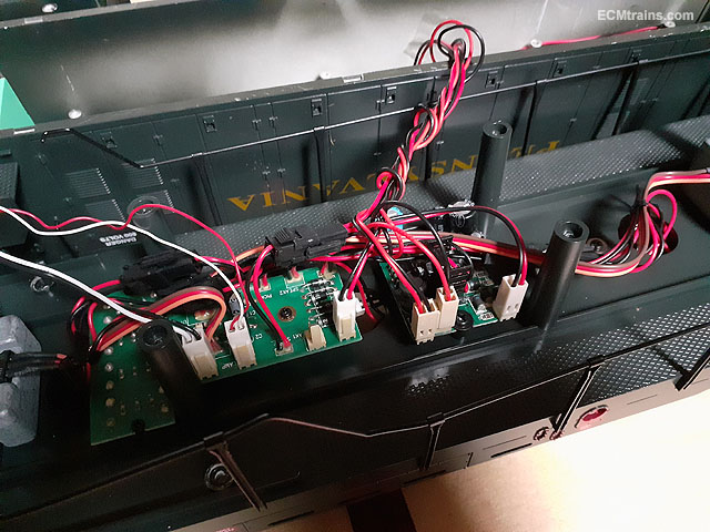
The wiring socket was then made up (sorry no photos) from mini connector soldered onto a PCB board which was screw mounted under the board featured above, a cad drawing print was stuck onto the top to indicate which connection was for what. The bogies, lights, smoke generators and cab light were all wired up and in this photo its all under test and being programmed.
The system complete and the hood about to be bolted down and then off for a test run on it's home layout.
The only problems encountered with the DCC chip, was with the analogue smoke generator boards, eventually the boards were take out of the loop and the generators were connected straight to the chip and controlled from there.
Unfortunately I lost the video of it running and making it's sounds, when the memory chip on the phone bit the dust. Next time when on a visit I will take some video of it.........
Eoin.
-
5
-
 3
3
-
-
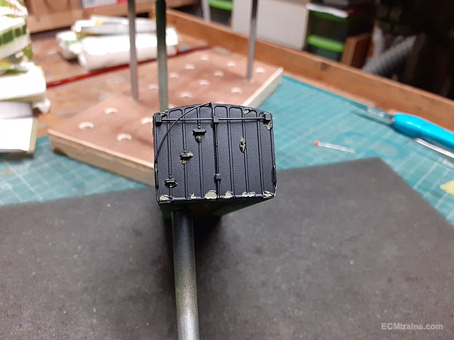
All masked up for painting the coach ends, Maskol was applied to the brake coach ends for weathering.
Painted two coats of Satin black.
Maskol being removed.
Some internal paint touch ups is required, but ready for door handles and lining.
Eoin.
-
6
-
-
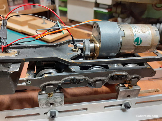
2 hours ago, Galteemore said:
That’s a beast of a Buhler motor!!
Yes is, it just about fitted in and it's geared very low running at 12-15volts.
I wonder if it's a 24volt motor?
Eoin
-
1
-
-
@angr607 The 141 is looking great.
Will your final kit incorporate louvres on the engine compartment doors?
And will the bogies have 141 detailed sides?
Thanks
Eoin
-
2
-
-
@ClaireSmiles Sean Ryan of the Train & Model Fair specializes in Gauge N models. The next Fair is on March 12th in Bray if you want to pay him a visit.
Or if you would like- private message me with your contact details and I can pass it on to him and if he's interested he could contact you?
Eoin.
-
2
-
-
The March Fair Date;-
-
1
-
1
-
-
Here is a video of Merlin running on it's home layout;-
Eoin.
-
9
-
1
-
-
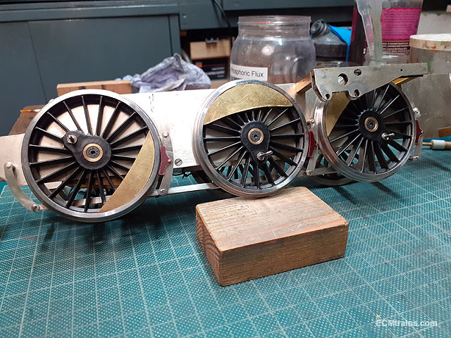
Brakes up Next;-
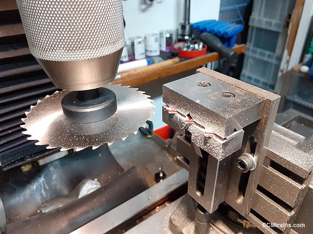
Brake shoes for the loco & tender being drilled and cut from Tufnol sheet. The shoes are 3mm thick.
The back of the shoes were then cut with a .5mm slitting saw for mounting on the hangers fixed with brass pins.
Some soldering work was needed on the tender chassis, those two brass mounting plates were soldered to the top of the chassis frames to give a bit more rigidity.
The tender chassis being drilled for the brake hangers.
All the brake parts for the loco & tender are ready. Missing from the photo are the loco brake pull rods!
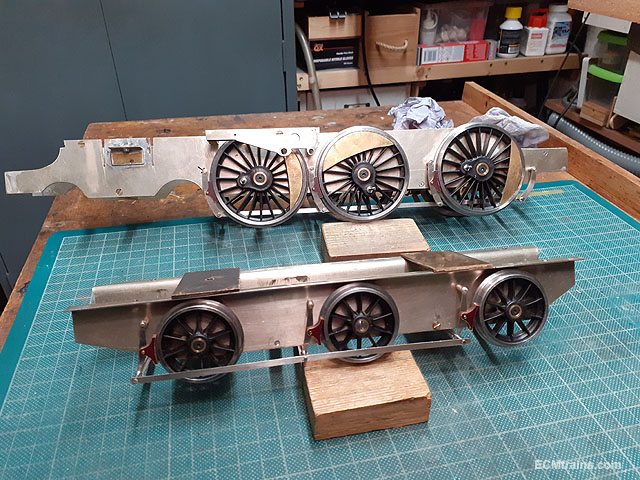
Soldering the hangers and cross bars.
Parts jigged up for final soldering together, the full assembly can be removed for painting.
Done.
Removed.
Loco chassis about to go through the same process.
All soldered.
The brakes are complete.
Drive and valve rod machining is next........
Eoin.
-
10
-
1
-
-
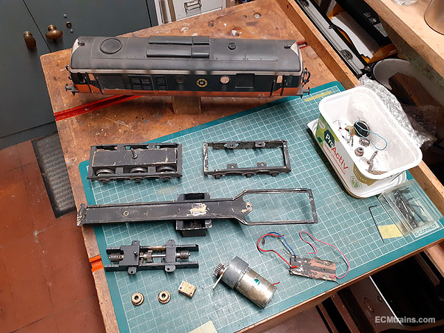
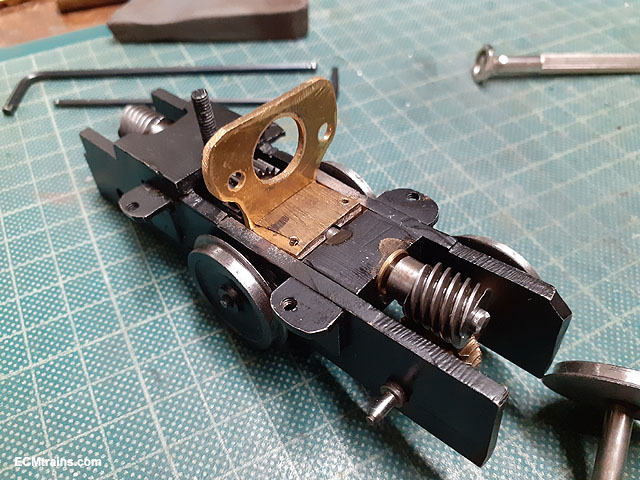
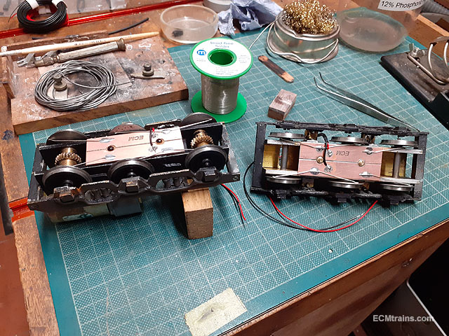
This is a Leinster Models Class A Gauge O, someone took it apart to do some repairs but never got it finished! The motor mounting bracket needs to be machined and fitted, new electrical pickup system to be installed, and the lot wired up to run.
The bits as delivered.
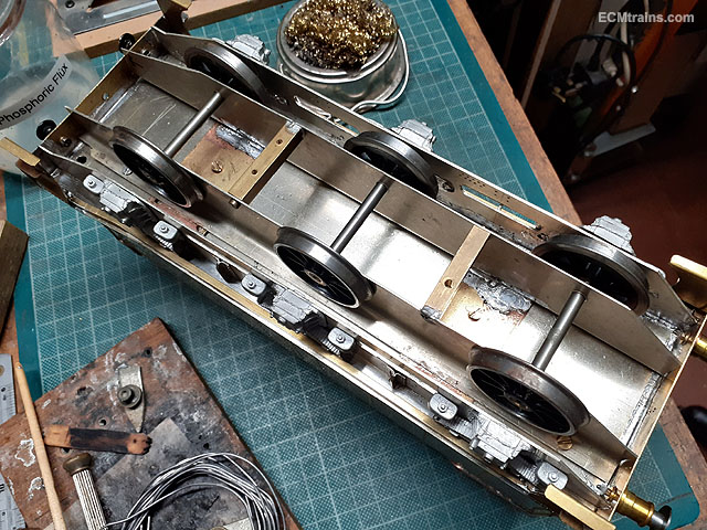
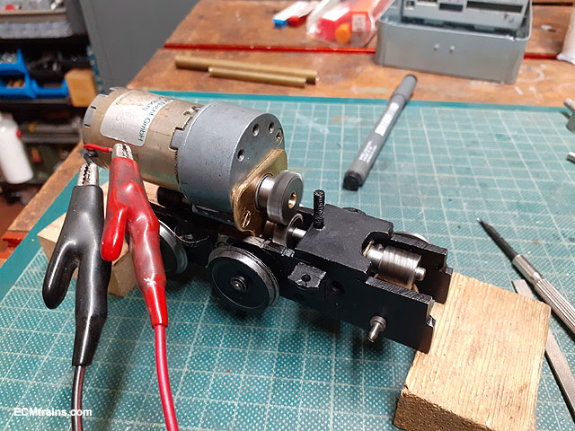
The motor mounting bracket was drilled for the motor and bolt mounted on that block of brass between the frames.
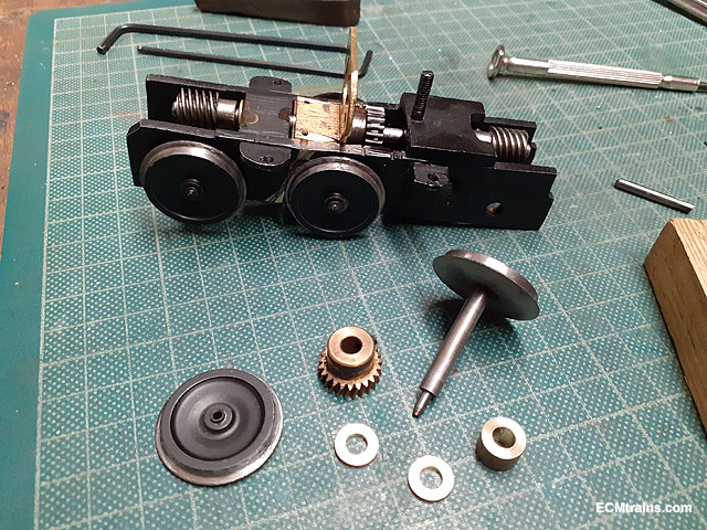
Axles being setup with spacers to keep the gears on centre.
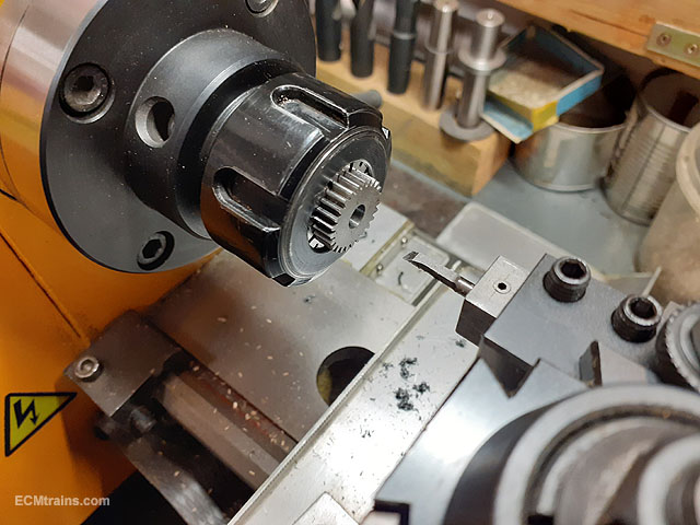
After setting up the drive gears the motor was installed to find the motor gear wheel had been drilled out off centre, this causing a massive wobble! The photo shows the gear wheel held in a collet chuck on the lathe and the centred hole being bored out oversize to take a brass sleeve to fit the motor shaft.
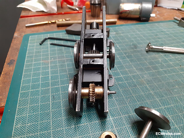
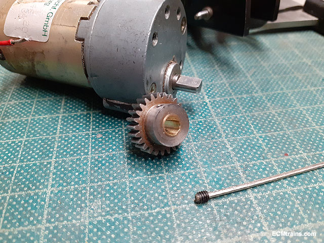
Drive gear finished with brass sleeve pushed in with a bit of Loctite.
The sleeve has a hole drilled in it to allow the grub screw to pass and lock on the motor shaft flat.
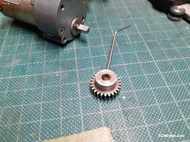
Runs smoothly now.
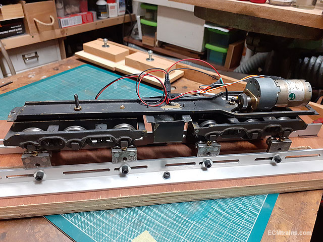
Setting up the front bogie for electrical pickups- first a slot was machined in the top of the bogie, with a screw installed in the chassis to stop the bogie rotating to much when mounted and damaging the wiring!
Soldering in two cross frames to hold the pickup board.
Cleaned up and mounting holes drilled and tapped.
.6mm NS wire was used for the pickup wires.
Pickups complete.
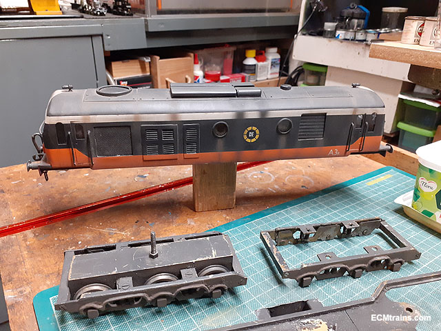
Wiring complete, with a DCC 8 pin socket installed.
Chassis under test on completion.
I forgot to take a photo with the body on!
Eoin.
-
13
-
1
-
-
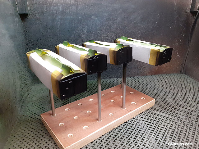
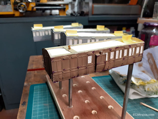
With a break from modelling over Christmas and my place turned upside down due to a housing development going on beside me, I've got very little done on these models! Though back into it now......
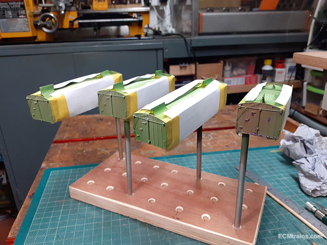
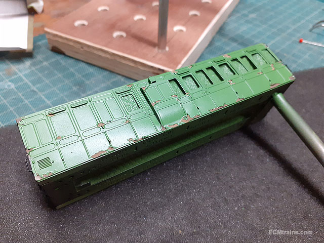
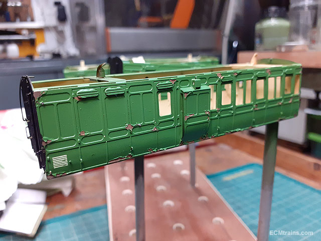
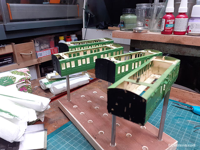
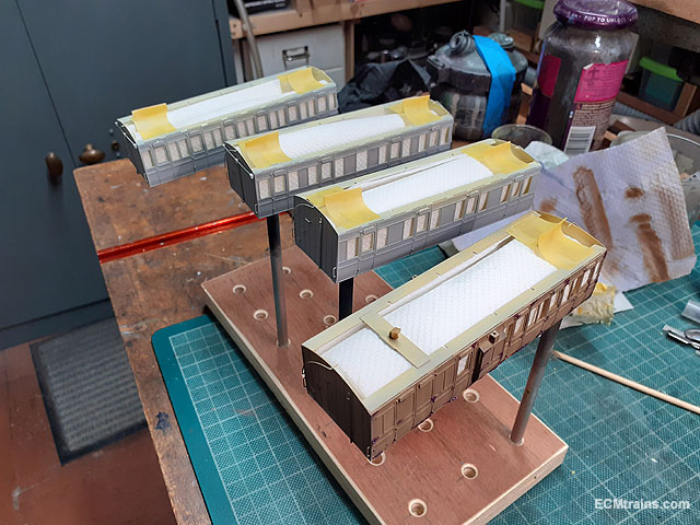
All masked up and ready for a bit of green.
Maskol was applied for the badly kept coach!
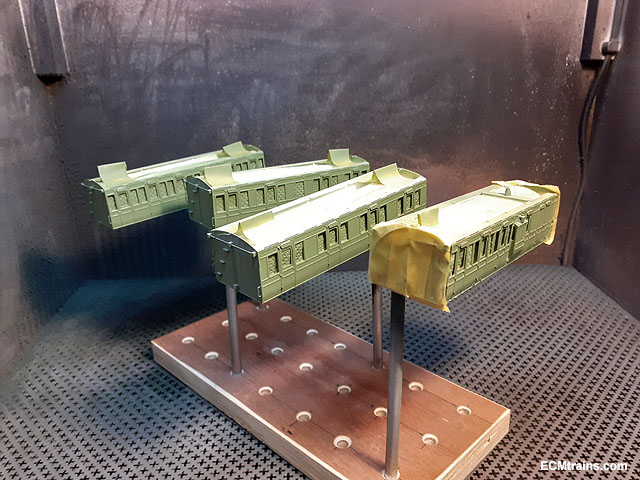
Base green undercoat applied.
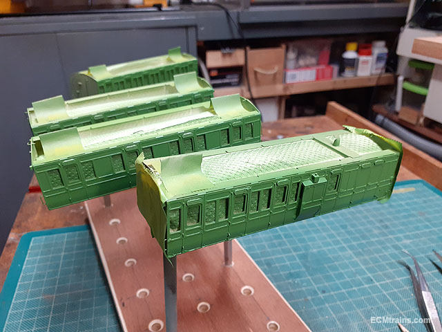
Two satin top coats applied.
Humbrol discontinuing their enamel paint range is a pain in the ass! All my colour mixes from over the years are now redundant and I have to start all over again.......
Eoin.
-
4
-
2
-
-
A chap- Jay Kovac posted this on fb recently, its 1:13.7 scale live steam and runs on gas
Stunning model.
There is a video of it running on fb also;- Irish Garden Railways
Eoin
-
9
-
1
-
-
Is there a DCC spring wire in one of the problem points? this would keep the siding track live!
Eoin
-
1
-
-
A bolt epoxy glued into the coach floor to extend down through the bogie with a nut under to hold the bogie on, some plastic card would need to be glued to the bogie top and bottom with a hole through for the bolt to pass, also you may need to adjust the coach downstand spigot with a file to get the height right. When the height is set use your favourite shade of nail varnish to lock the nut in place and allow a bit of play for the bogie to wobble side to side, nail varnish is better then threadlock as it open easier and wont break the epoxy holding the bolt in!
Eoin
-
4
-
 2
2
-
-
21 minutes ago, Broithe said:
Mine are the ones for posh people.
I think I can claim poshness as I have four of them even tough no hooks

Eoin
-
1
-
-
No hooks on mine!
Eoin.
-
1
-
-
@Broithe yes they are very handy, and yes the plastic does not like sharp impact, I have four of them with two suffering the problem you have.
Eoin
-
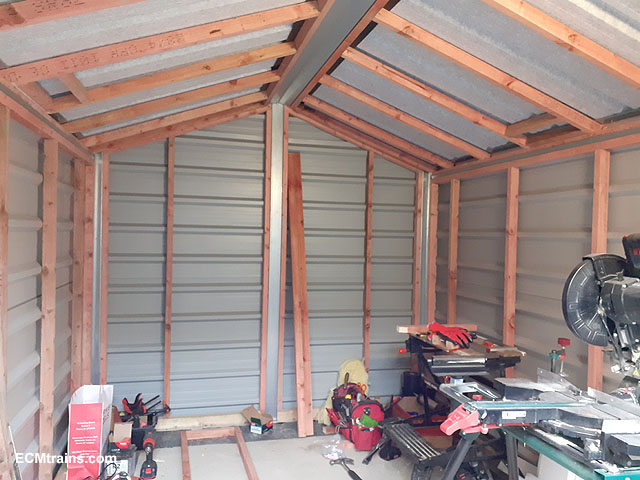
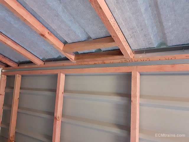
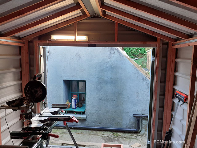
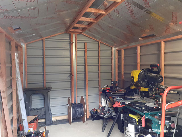
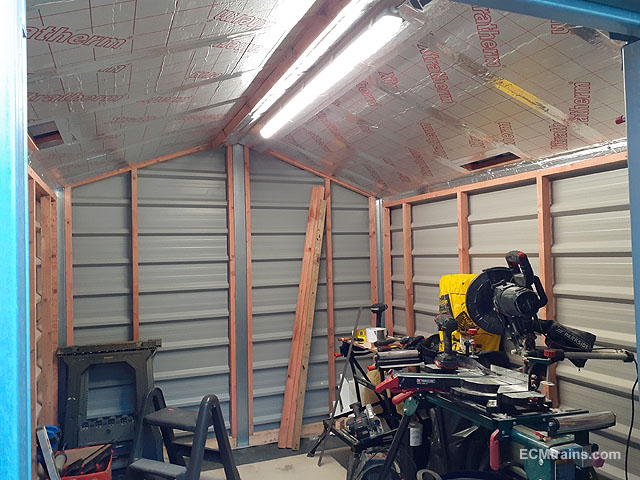
I got a bit done on the internals of the 'Lathe Shed'
50x35mm treated timber studs installed.
The shed roof steel sheets were raised up with 10mm thick plastic washers at the eaves! The grey material on the roof sheeting is a drainage sheet, it's stops condensation dripping off the ceiling, but because the sheets were screwed down to that steel eaves beam the water in the sheet drained onto the beam- this would cause the timber to rot over time.
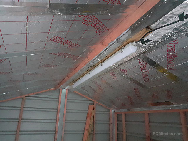
50mm roof insulation installed, ridge pelmet test fitted to see where the light fitting would end up, height wise.
Pelmet modified, fitted and insulation installed.
Light!
Eoin.
-
4
-
-
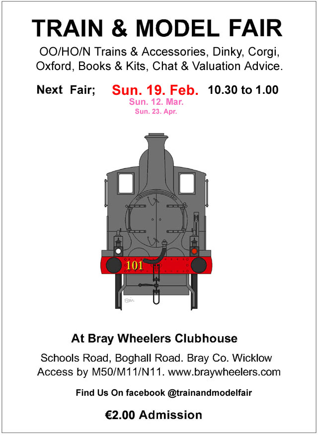
The February Fair Date;-
-
3
-
1
-
-
-
Mayner does a etch Fish Van Kit;-
Eoin.
-
1
-
-
2 hours ago, Peter said:
Hi folks,
I'm just wondering if Des Sullivan is active on the forum? If he is, does anyone know his username? I'm trying to get a couple of packs of n gauge transfers.
Cheers, Peter
You'd have a better chance by contacting him through his website email, he does take time to respond......
Eoin.
-
2
-


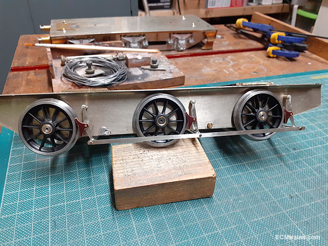
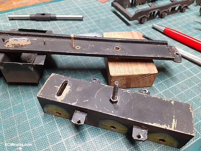

Class 850 / P1 Gauge O Works
in ECM Model Trains
Posted
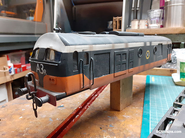
This model has been on the workbench for some time now, it's a Brendan Kelly/Hamill built model. Now that a number of projects are complete I can dedicate more time to get it finished.....
After having a good look a it and a bit of photo research a plan of action was worked out. The model has been prematurely painted as it's lacking a number of critical parts;- cylinders, valve gear, coupling rods, brake gear, cab opening details, cab roof rain strips, electrical pickup system, footplate frame details and buffers. Although it looks fine with paint on, there are a number of locations on the body that solder could be removed to improve the detail- so it was decided to remove the paint and start there.
Sand blasted
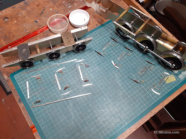
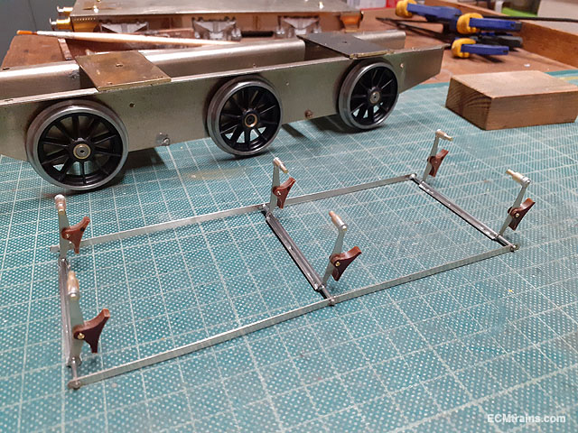
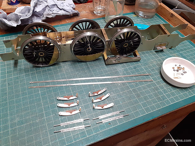
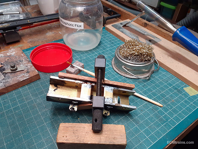
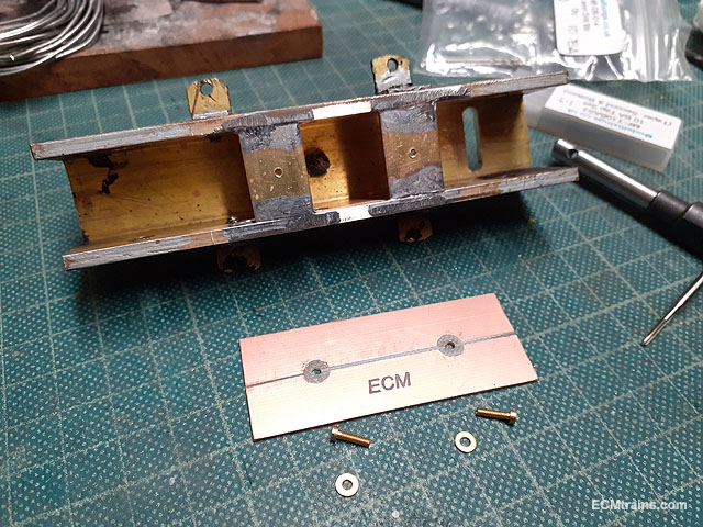
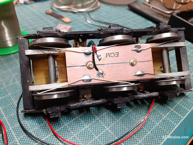
Bits were acquired and the electrical pickup parts are prepared.
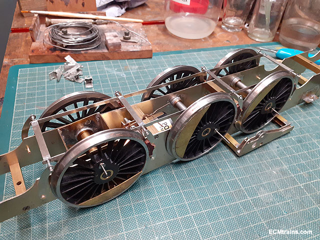
Solder clean-up almost complete.
This is a screen capture of the CAD drawing, the drawing was done to work out how to make the cylinders, crosshead, rods, brakes, and a few other bits, the drawings of parts are extracted out to the right, for CNCing from metal sheet.
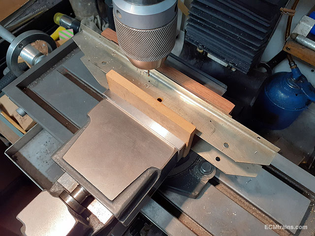
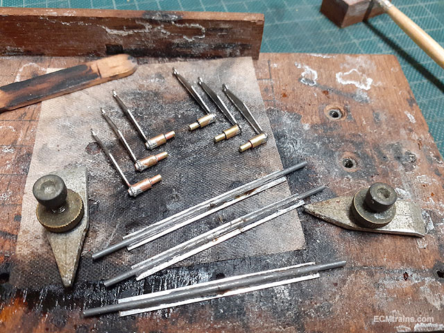
These bits are the tools for making up a new steam dome, there are tools for both Gauge O & OO. The long round bars are the boring bars for turning the base of the dome to fit on the boiler. The short round bars and screws are for mounting the dome in the lathe chuck to form the top curves. The square bars are for holding the carbide tools while sharpening them on the grindstone. There is another square bar yet to be made for holding the work piece in the lathe tool post while the base curve of the dome is being cut.
More later......
Eoin.