

murrayec
-
Posts
2,668 -
Joined
-
Last visited
-
Days Won
68
Content Type
Profiles
Forums
Resource Library
Events
Gallery
Blogs
Store
Community Map
Posts posted by murrayec
-
-
It would seem that the link above is not available to the public anymore!
But this popped up in youyube;-
Eoin.
-
 3
3
-
-
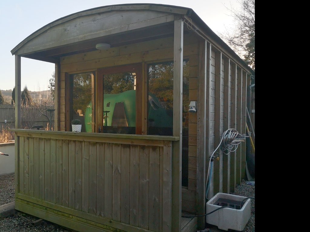
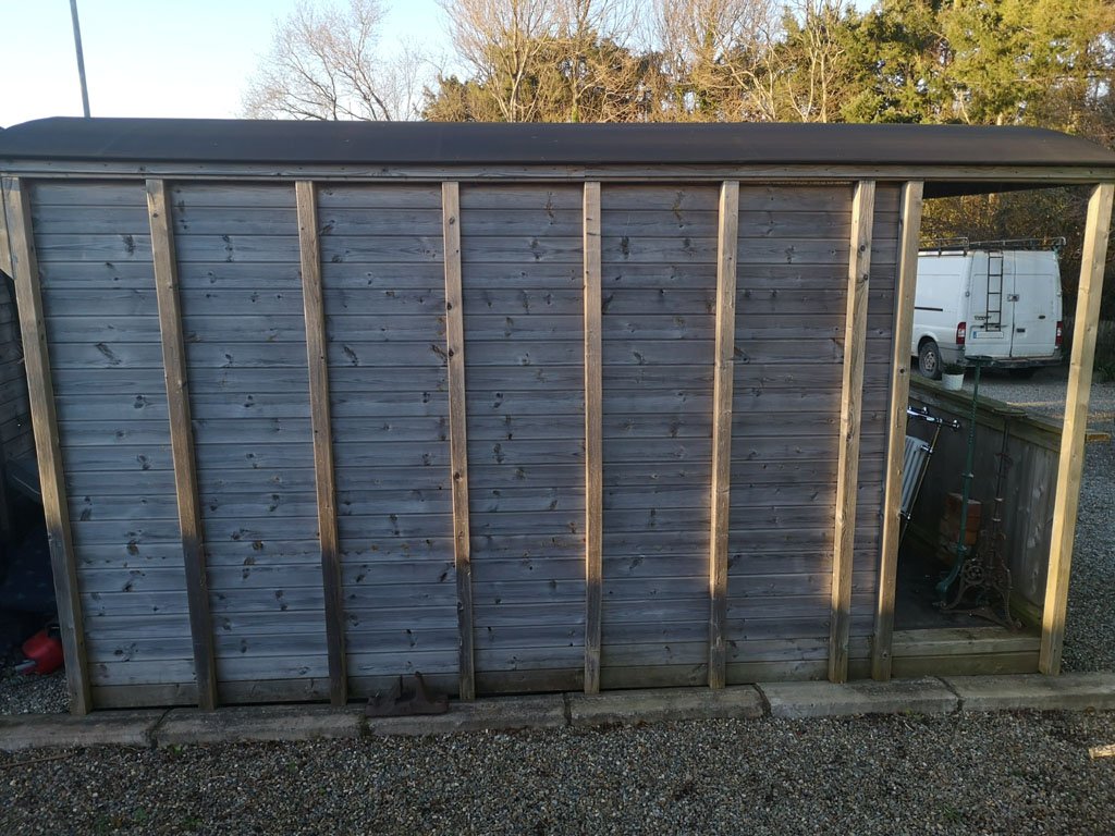
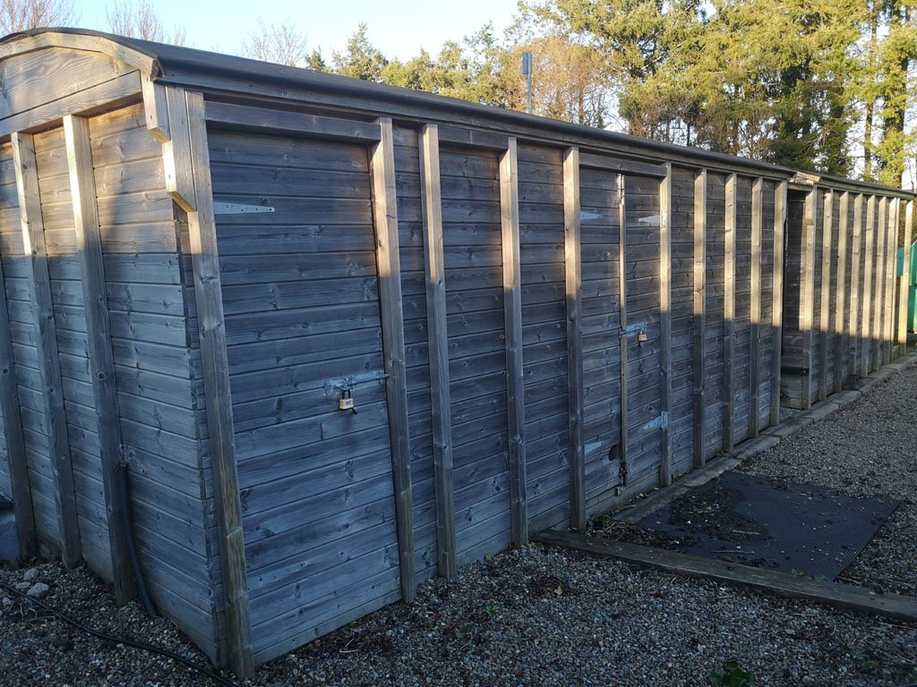
@Gabhal Luimnigh Here are a few photos of the sheds I mentioned above, I know it's different to what you have in mind but it gives some ideas, especially the ground level detail;-

Eoin.
-
3
-
 1
1
-
 1
1
-
-
Check out the resources on here for dimensional ideas;- https://irishrailwaymodeller.com/resources/proto_drawings/
Eoin
-
1
-
-
@Gabhal Luimnigh Not sure about the availability of the IRRS drawings- Anthony McD' looked after the drawings but sadly he passed away a few years back, though contacting them will answer the question of availability?
Line drawings with principal dimensions can be found in Ian Allan's publications like;-
'Narrow Gauge Rolling Stock' by Desmond Coakham.
'The County Donegal Railways Companion' by Roger Crombleholme.
I know they are a different gauge but a great starting point, also I sure more published drawing recommendations can be offered on here!
I also know a man who built 2 storage sheds in wagon fashion, if he is agreeable I could get a few photos of what he did if you like?
Eoin
-
1
-
-
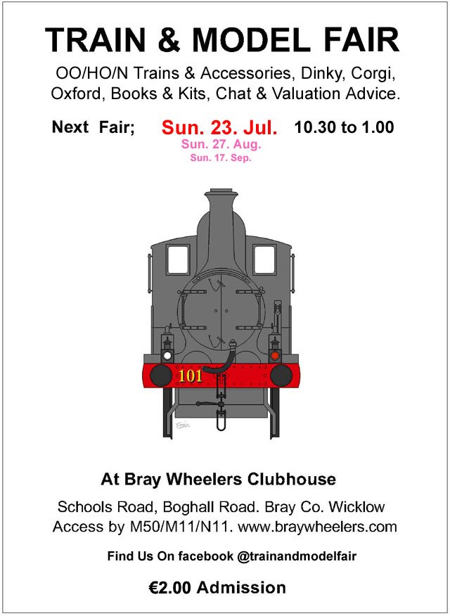
The first 2024 fair date;-
This years flyer is sporting 'Bat'
Happy New Year
Eoin
-
4
-
-
@LNERW1 I for one, would be delighted if you post up photos of the locos & stock.......
Eoin
-
2
-
 2
2
-
-
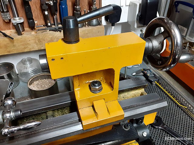
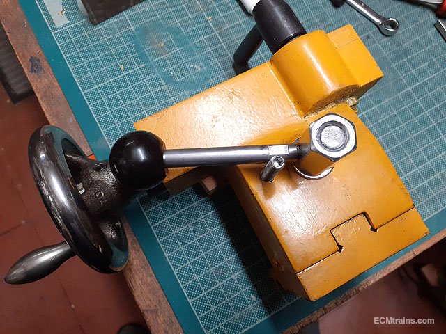
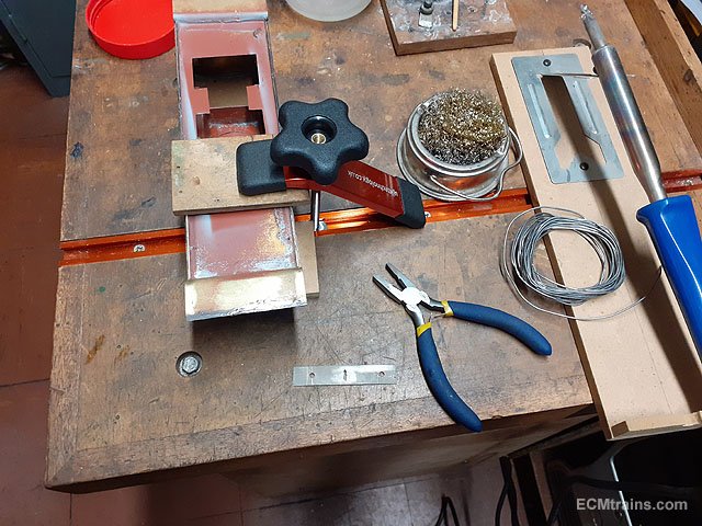
Modifying the Clarke Mini Lathe Tailstock;-
The standard Mini Lathe tailstock comes with a basic system to clamp it down to the lathe bed- a nut n bolt requiring a spanner to operate! There are options when purchasing the lathe, one is a lever-cam tailstock clamp, but Clarke do not have this option. Others do, also kits to convert are available on-line.
The use of a spanner every time to clamp & unclamp is a pain- lever action would be much better.
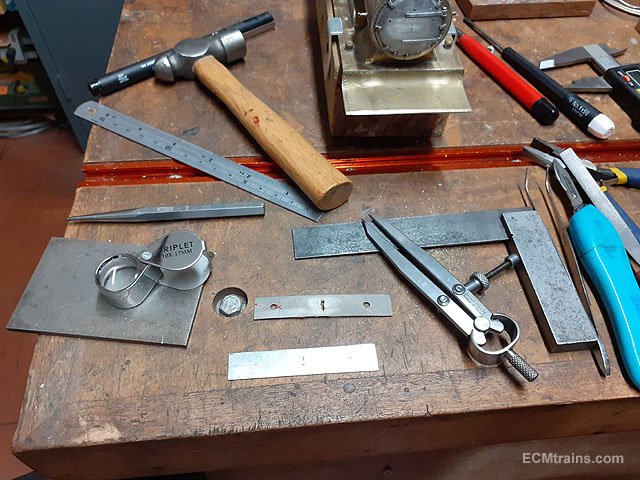
I found a chap on Youtube who did the conversion with;- M10 threaded bar, M10 bolt, M10 coupler nut, M6 capscrew, 4mm MS plate, and a length of 8mm dia MS bar for the lever handle.
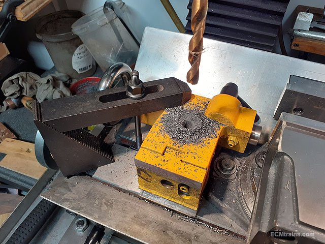
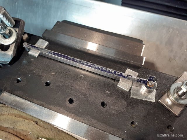
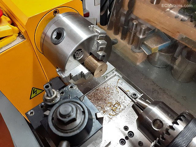
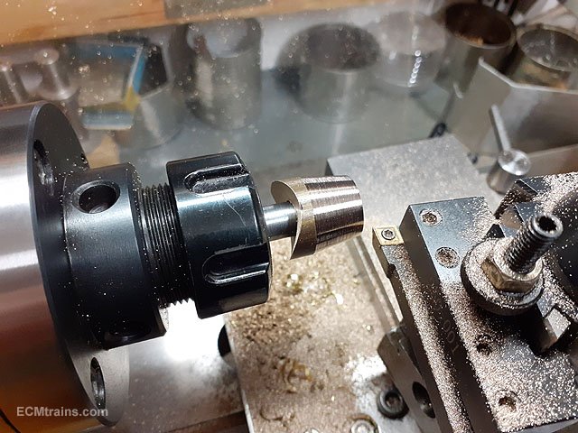
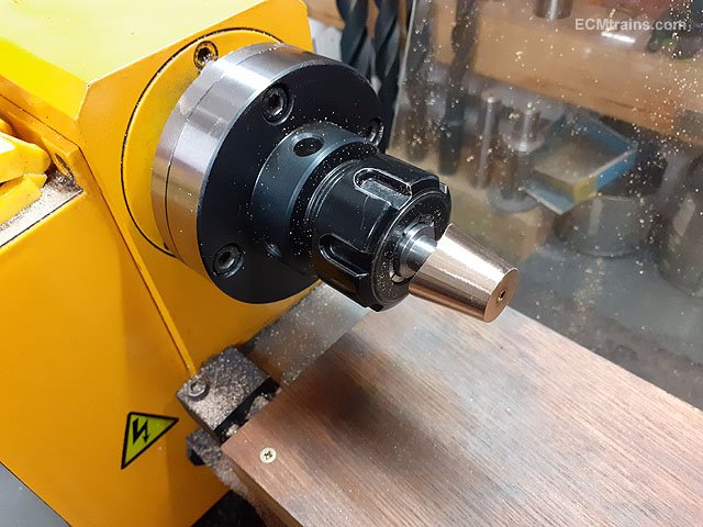
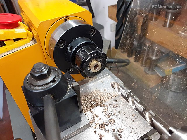
The existing tailstock clamp setup.
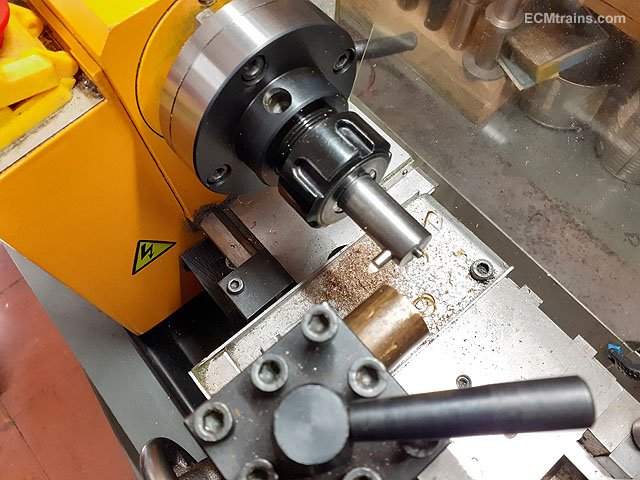
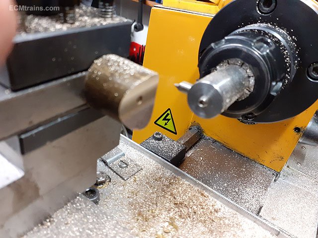
Drilling the 10mm dia hole for the cam bolt to pass through to the rear of the stock where the lever will be fixed.
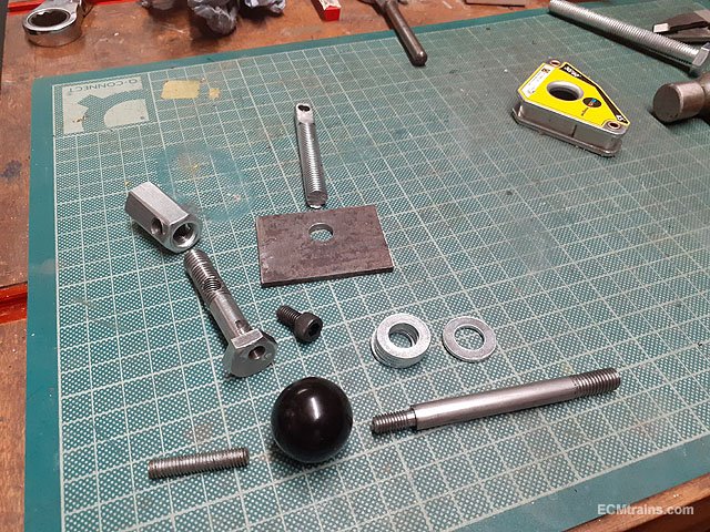
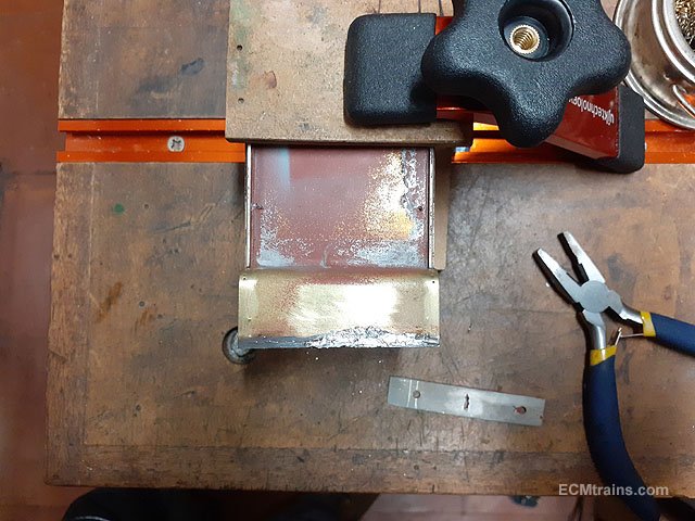
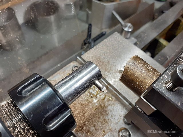
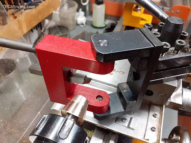
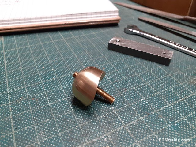
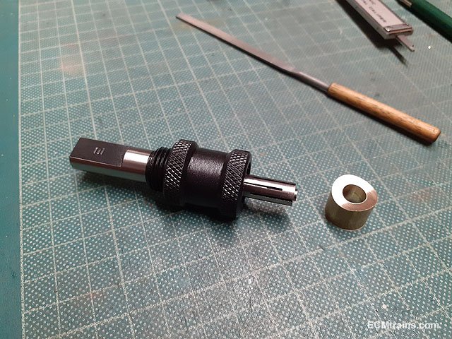
All the bits, the cam bolt has the M6 capscrew threaded in its head 3mm off centre to create the cam, the coupler nut holds the cam bolt in the stock body which is cross drilled and tapped M8 to take the operating handle.....
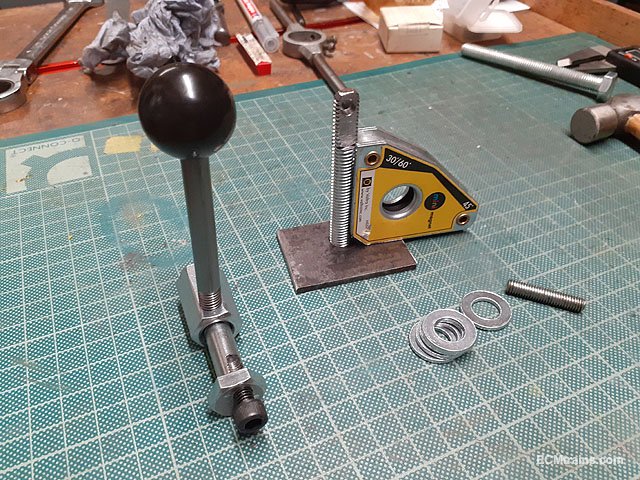
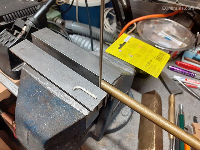
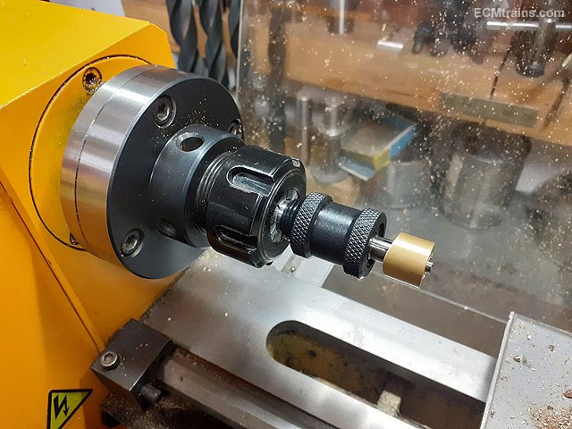
........like this. The clamp plate and the M10 modified threaded pull bar needs a weld on the underside. This pull bar is cut to size so that the cam rotates anticlockwise from 4 o'clock up to 1 o'clock where the mechanism locks, thus locking the tailstock to the lathe bed. The washers are used to pack the clamp bolt in the stock to line up with the pull bar.
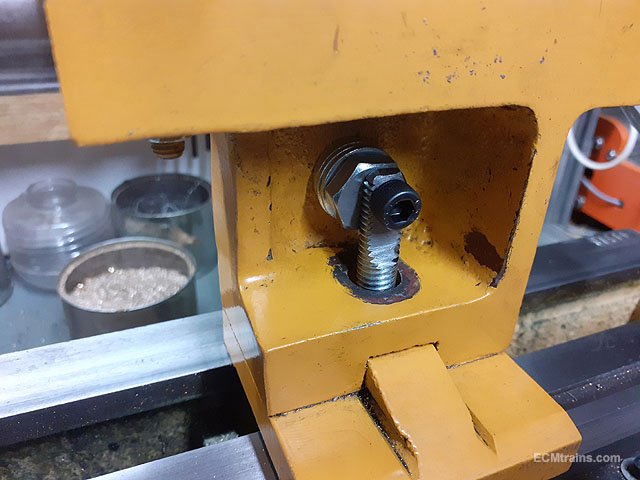
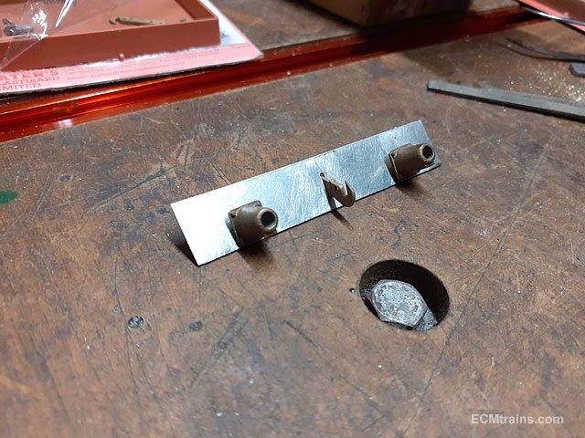
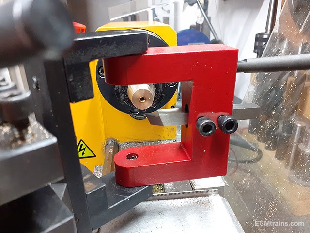
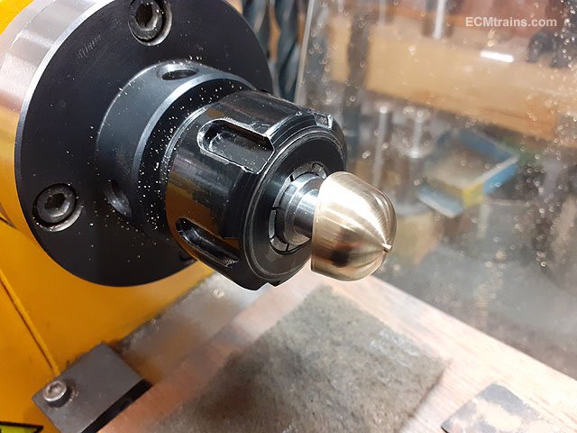
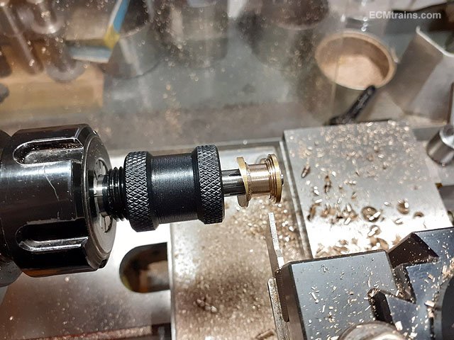
The cam arrangement with the M6 capscrew and washers fitted.
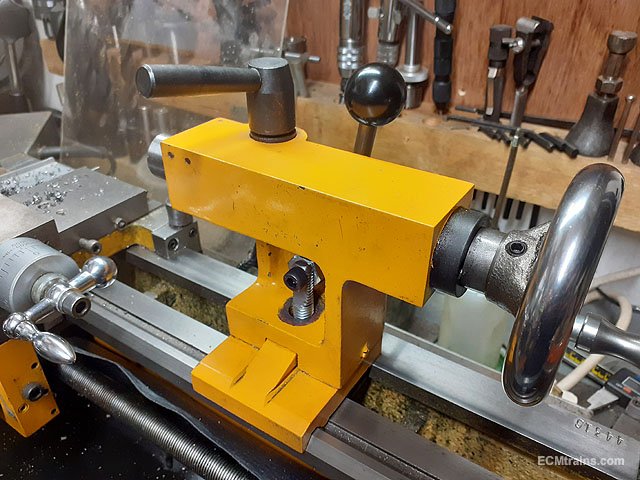
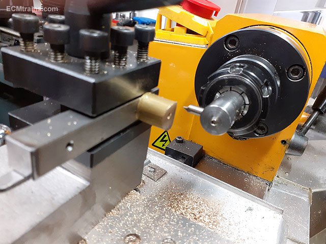
A M6 grub screw was drilled and tapped into the stock body to hold the handle in easy reach when the tailstock is unclamped. Flats were milled on the lever handle for a 7mm spanner to tighten it up.
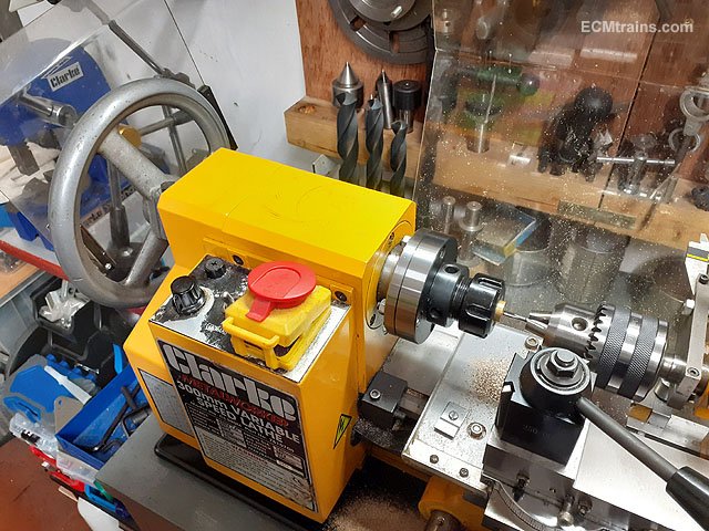
Up and running, it works beautifully, holding the tailstock rock solid.
I wont need that spanner any more.
Eoin
-
6
-
-
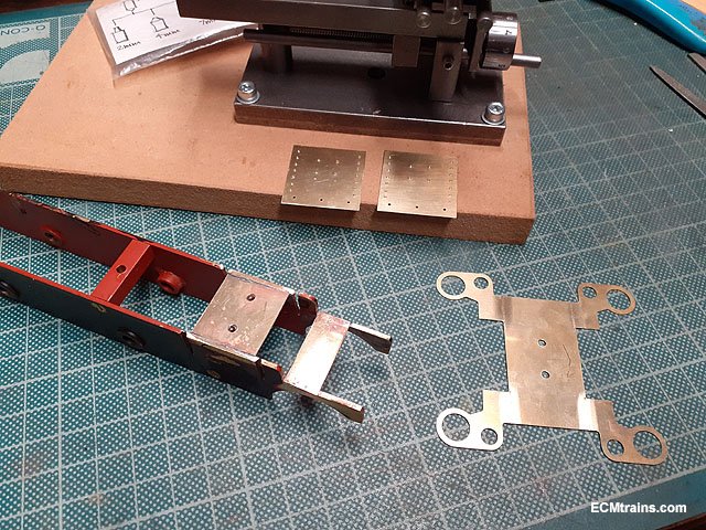
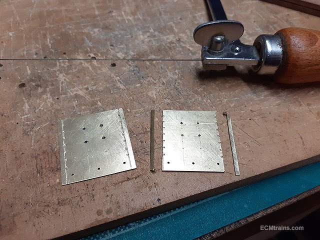
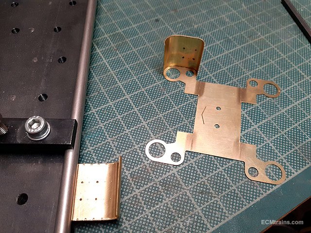
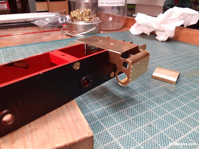
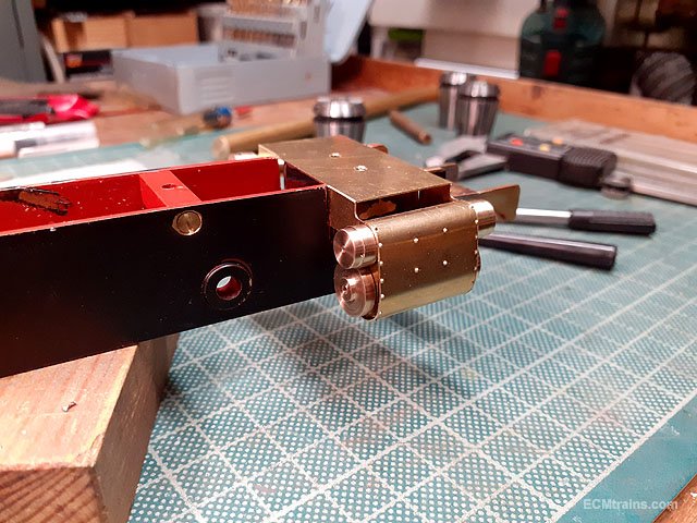
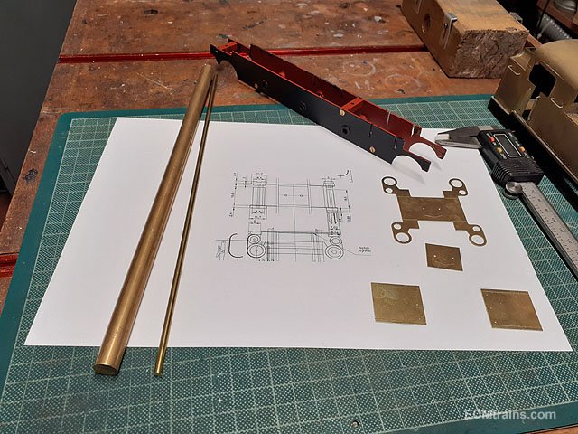
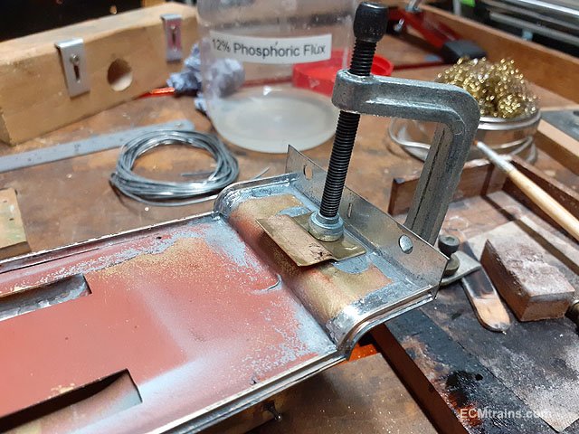
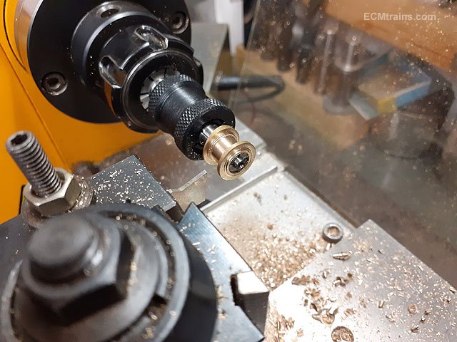
Time to make up the cylinder parts.
A stretcher plate was made up and soldered between the frames to mount the cylinders on the chassis and the cylinder covers had their rivets popped.
Two 8BA nuts are soldered to the underside of the stretcher plate for fixing the cylinder assembly.
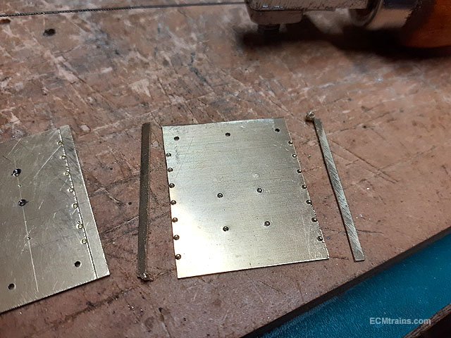
The cylinder covers had extra meat on the sides so that the sheets would not distort during the riveting process, this extra was cut off using a piercing saw.
A bit of cleaning up required but the rivets are right on the edge with no distortion.
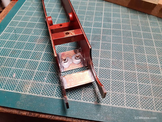
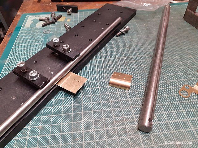
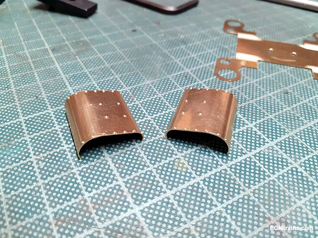
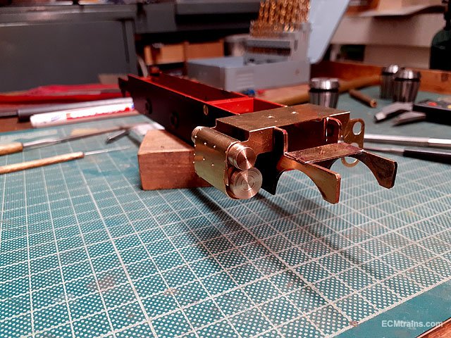
A bit of bending
Done.
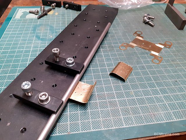
The cylinder frame was folded up and the covers are adjusted to fit.
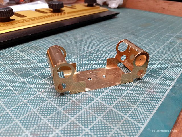
Having a look
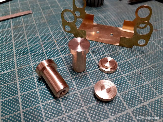
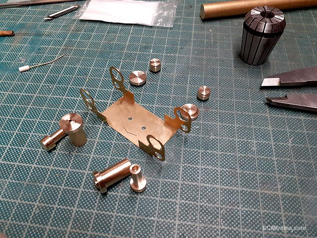
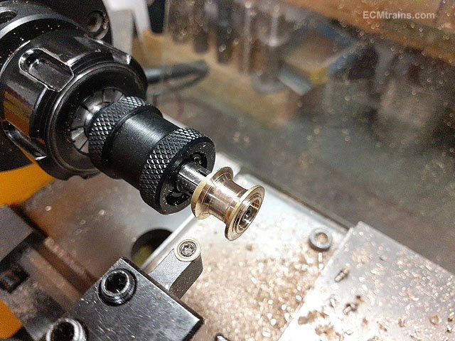
Next was the cylinder parts, turned up on the lathe.
The full bunch, complete and ready to test fit.
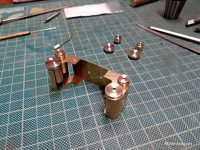
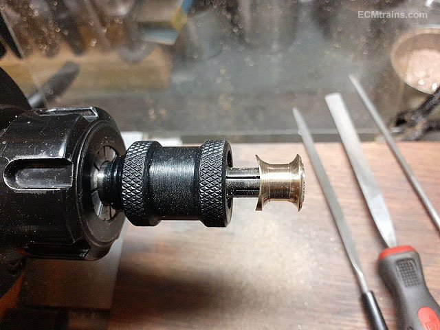
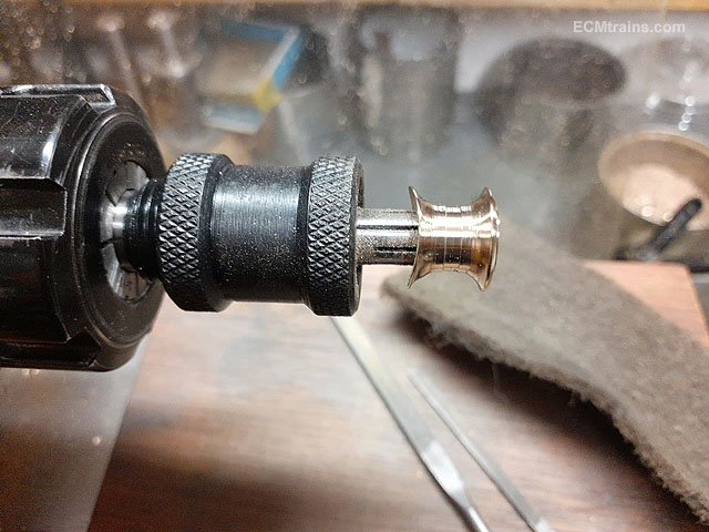
A bit of broaching was required but everything works!
A few more bits to process and then the lot can be soldered up.......
Eoin.
-
6
-
3
-
-
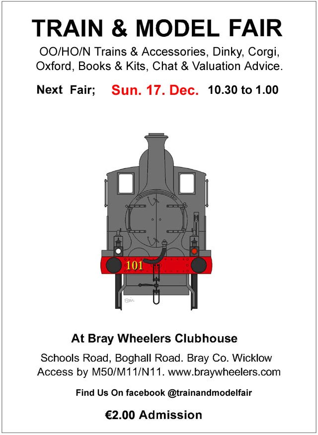
December Fair Date;-
-
4
-
-
On 18/11/2023 at 10:02 AM, Fiacra said:
Apologies for such a basic question, but how does one go about removing the bogies from a MM mk2d? I thought they might disconnect with a bit of force, but that starts pulling the whole chassis away from the body, so it must require a more nuanced approach.
Thanks for any help!
Hi,
The bogies pop off when levered up from one end, it needs a bit of force though
Eoin
-
1
-
-
After a brake from major modelling works for the last 6 months, due to family situation and house building works, I'm now back at it!
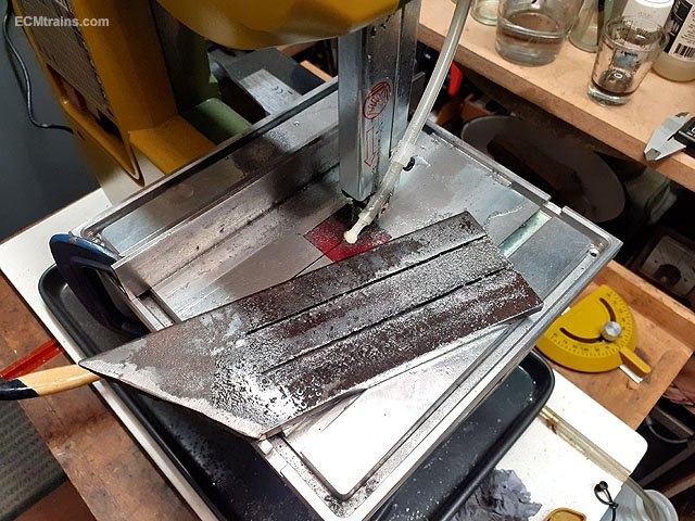
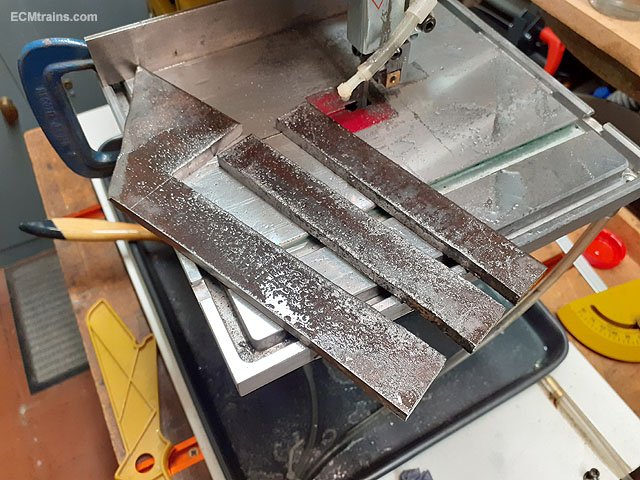
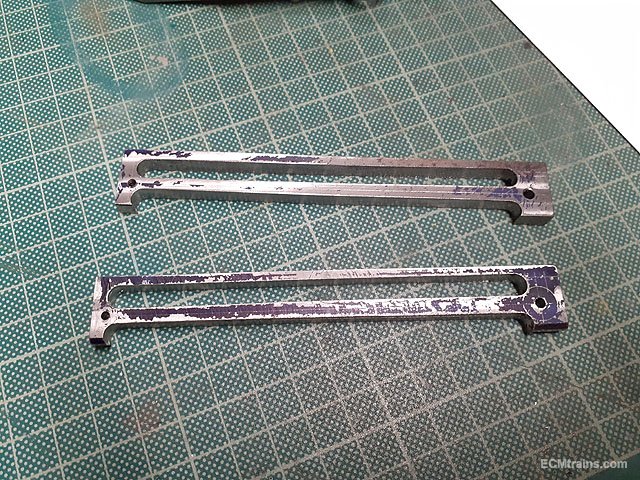
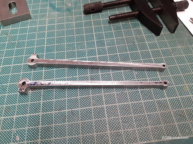
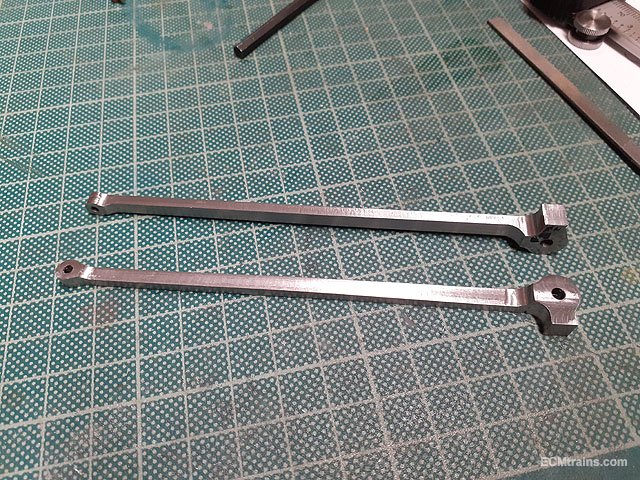
This is the machining of the drive rods, it's similar to the coupling rods but with a taper twist!
Two lumps of 6mm thick MS were cut out on the band saw.
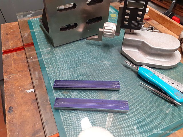
The rough shape of the rods were marked up to aid machining, I was a bit short on the length of the metal which made clamping a bit of a nightmare, but it worked out OK in the end.
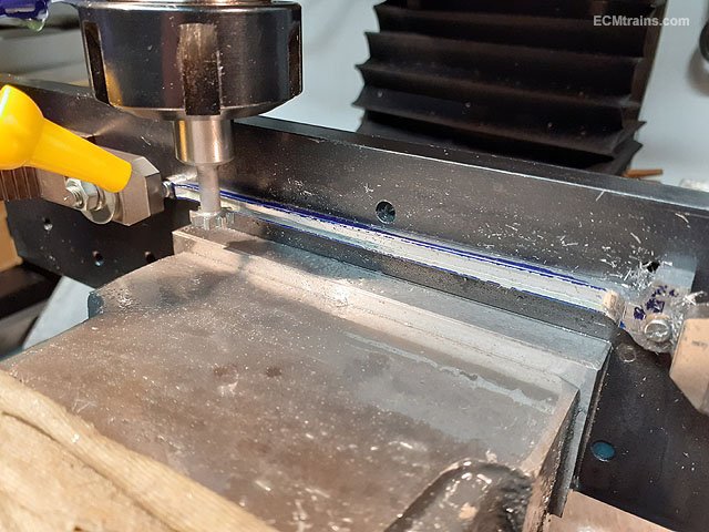
Setting up the blanks for drilling the holes, which are drilled through into the plate under. The holes in the plate are then tapped 8BA for bolts to locate the blanks on the plate. The small end of the rod is drilled to a tight fit on the 8BA bolt and the big end is drilled out 3mm but held by a 8BA bolt, this allows the blank to swing from side to side at the big end allowing for the taper to be machined.
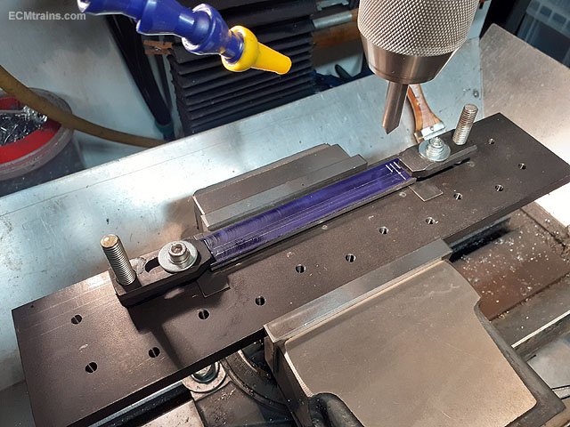
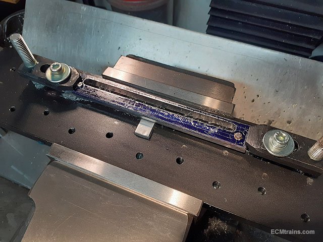
The upper edge milling complete, done while the blank is clamped forward (towards the camera) creating the upper taper. The clamping is about to be released to push the big end back the other way, clamped again, and the lower taper will be machined.
Both tapers done.
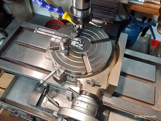
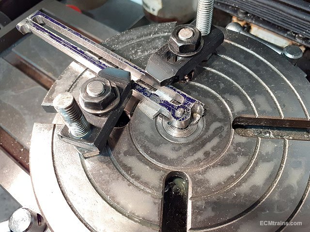
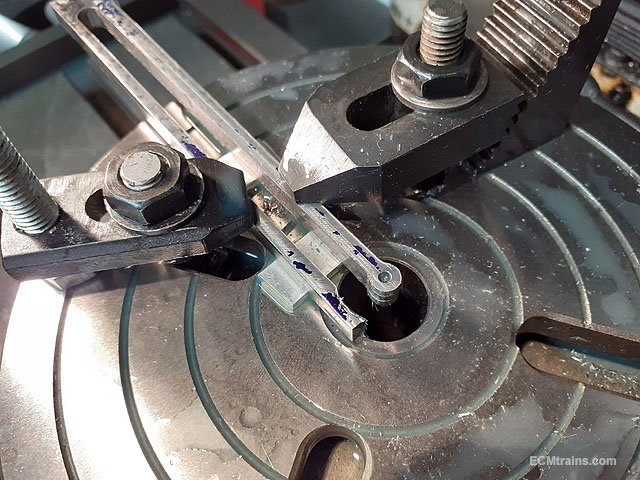
Next the parts are clamped down to the rotary table to machine the rod ends.
Big end done.
Small end done.
After cutting off the excess metal at the big end with the band saw the oil boxes were machined on the clamping plate.
Rod profile shape complete.
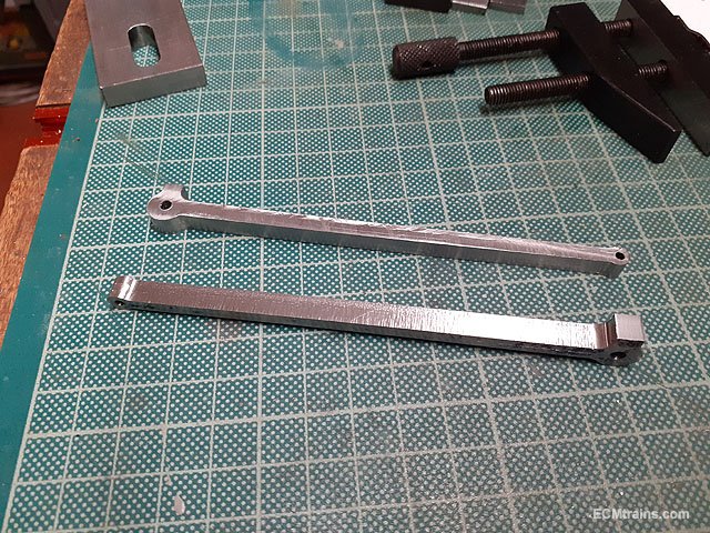
Next is the setup to thin the rod shanks, this was done on the clamping plate vertically in the vice, an 8mm end mill was used to side cut 2mm off the shanks, leaving 4mm radius curves out to the rod end bosses, the big end is 6mm thick and the small end is 4mm thick.
Done.
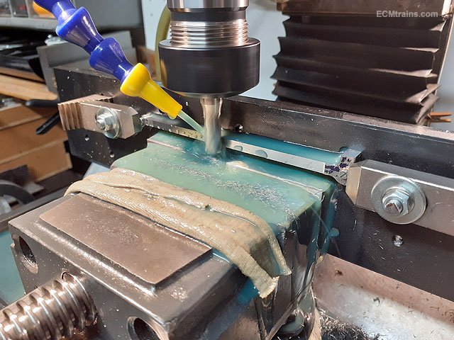
Now the flutes are machined using a 2.4mm x 9mm dia woodruff mill cutter, this is done as per the taper cutting above so that the flute follows the taper on the rod edges. The flute is cut 1mm deep and tapers out flush with the rod end bosses.
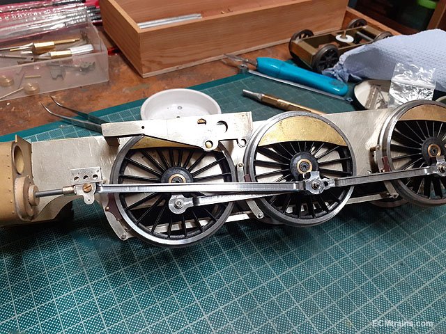
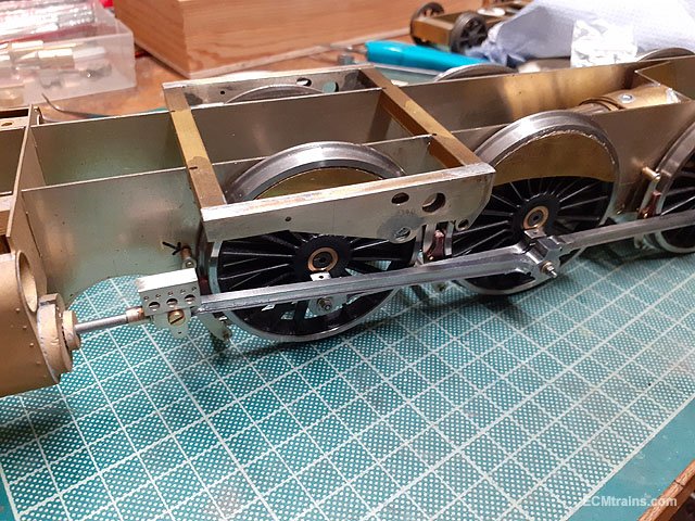
Rods complete and been fitted to the chassis, some cleaning up of machine marks is needed at a later stage.
Some of the cylinder parts previously made are now fitted.
Body on.
Now that these rods are complete the crosshead slide bars can be fitted and sized, also the slide bars end brackets can be finalised n soldered on to the motion plate, then the rest of the valve gear...............
Eoin.
-
7
-
5
-
-
Novembers Fair Date;-
-
2
-
-
Octobers Fair Date;-
-
3
-
-
Excellent work n design Ken.
Eoin.
-
1
-
1
-
-
Hi James,
The Hornby Elite is known as a problematic controller, I would suggest trying the locos on a friends controller of better quality if you can! This would eliminate your controller from the programming/test of the locos and see what happens then.
You should consider upgrading to a better controller- Roco Multimaus is a good starter, Roco Z21 would be next but more expensive, and there is more......
Eoin.
-
1
-
2
-
-
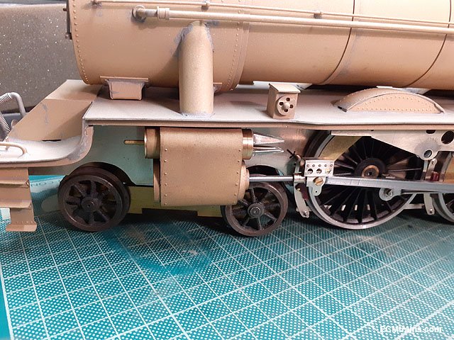
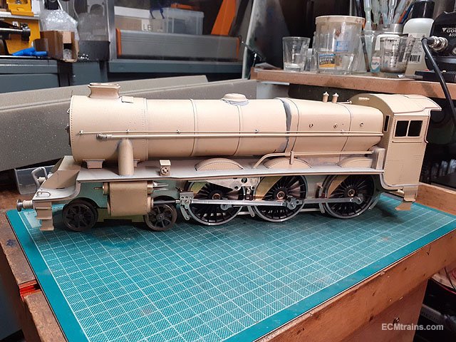
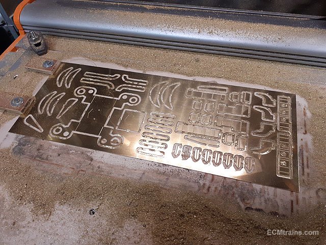
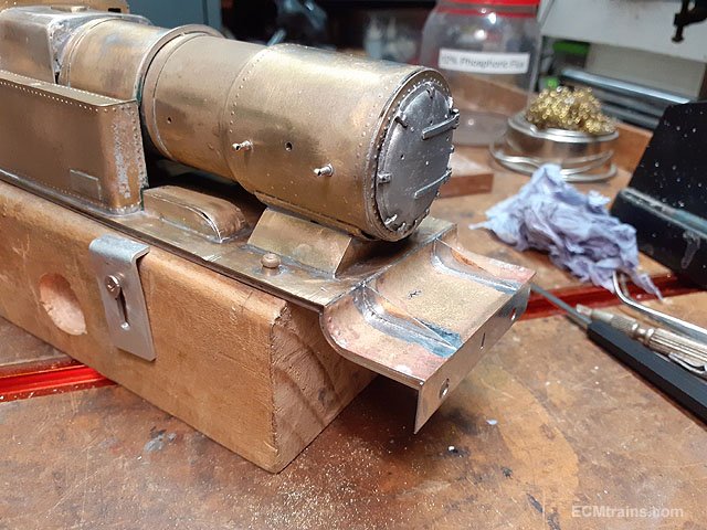
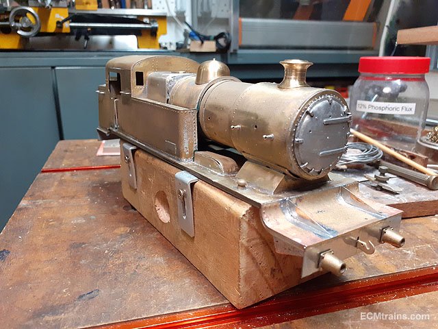
Work on 850 continues;-
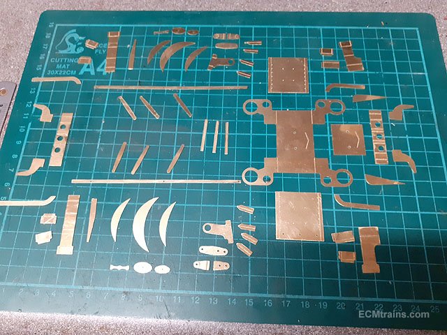
Parts cut out on the cnc machine and cleaned up.
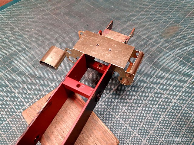
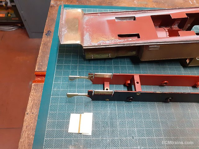
When starting to set up the cylinders I realised that the chassis first needed its fixings to the body so I could work out the space I had to work with- the front of the cylinders are rather close to the front footplate down-turn. Also, the front valance parts need to be in place.
The front of the chassis will be held by a tab soldered to the underside of the footplate with a cross piece across the chassis frames to slide into the tab, the rear will be screw held to the body under the bunker.
The dodgy front buffer beam was removed.
One can see here, how off line the front footplate is.
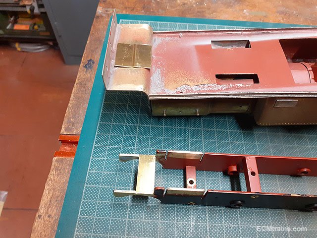
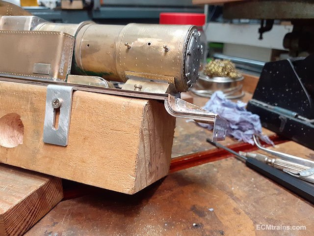
A new buffer beam being setup in tin-plate and the footplate has been corrected.
Beam holes drilled and hook slot cut out, now ready to be soldered on.
Front valance pieces were made from OO track rail to match that on the body. I did cut brass parts out for this but decided to use the rail instead.
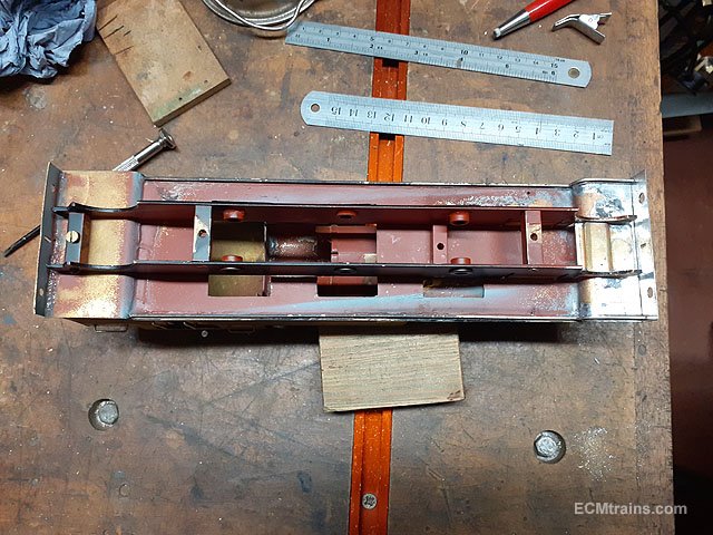
Footplate chassis frame parts are soldered on.
Same with the front valance parts.
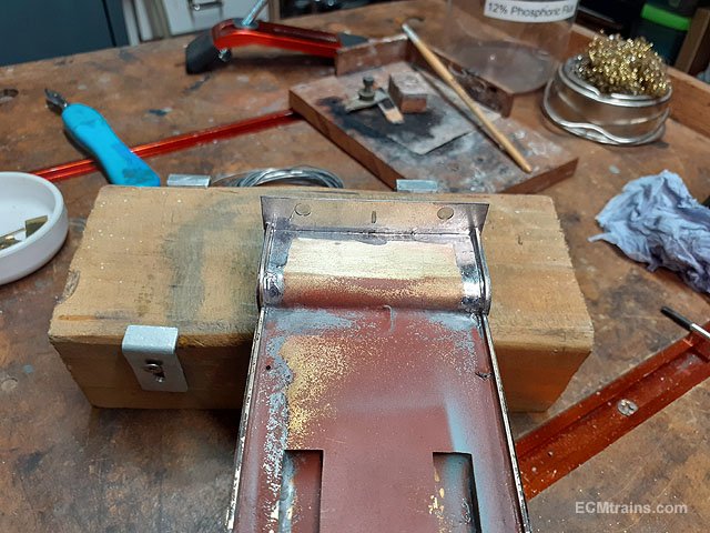
Chassis mounting tab pre-thinned ready to be solder on the underside of the footplate.
Clamping arrangement for soldering.
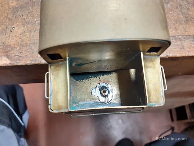
After sorting where the rear screw will be, a hole was drilled in the floor of the bunker for a 6BA nut to be soldered in.
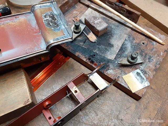
Chassis fitted.
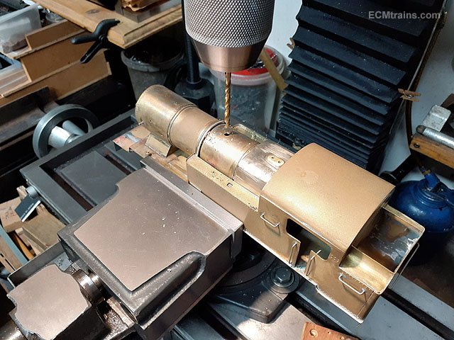
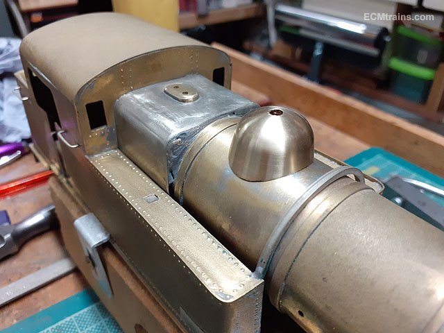
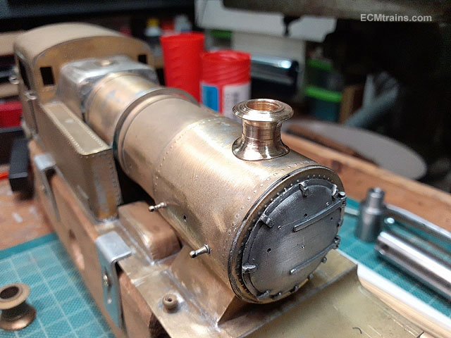
Drilling holes for the boiler fittings- steam dome, snifting valve and chimney.
Done for now.......
Eoin
-
9
-
3
-
-
September Fair Date;-
-
1
-
-
The August Fair Date;-
-
4
-
-
@DJ Dangerous Paul Spooner - the man for automata! If he were a railway modeller he would have automated working crew in all his locos!
I have built one automata railway wagon with a man dancing a jig as the wagon is drawn behind a loco! It was based on Spooner ideas. I may show it sometime later!
Eoin
-
2
-
-
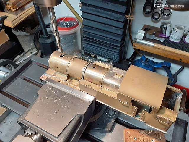
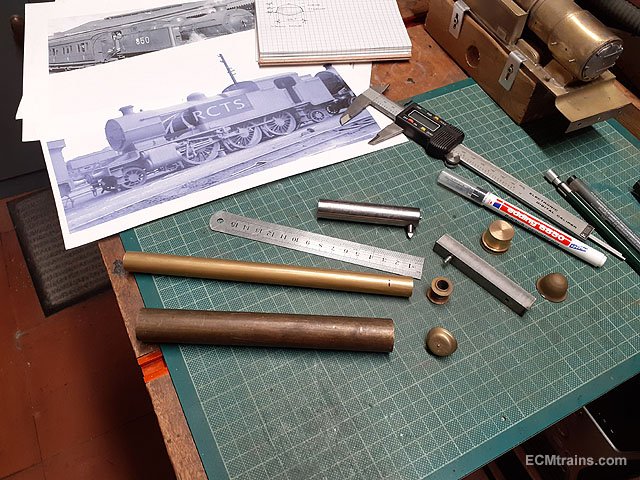
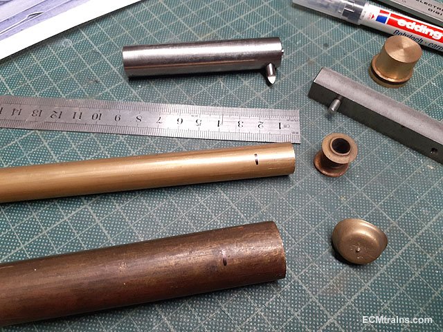
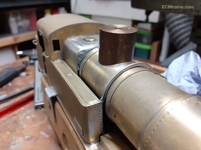
Having a go at the new steam dome;-
After working out the sizes (I also decided to make a new chimney- slightly smaller then the one removed), two slugs of brass were cut from bar- 22mm dia for the dome and 15mm dia for the chimney.
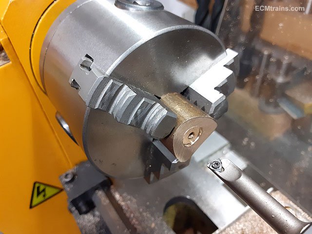
The dome slug in the chuck just about to be tapped M4 for mounting in the toolpost bar to cut the boiler curve on the base of the dome. The radius is 17.5mm
Now mounted on the toolpost bar, set at 90 deg and ready to fly cut.
Cut- slightly out of focus! The mounting bar required 3mm packing to get the work-piece centred on the axis of the lathe. The first light cuts show if your on centre, then one packs out until the cut is centred on the tapped hole.
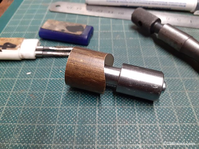
Checking fit.
A recess is bored out of the base for the work to be mounted lock-face on the mandrel.
Now the work-piece is mounted on the chuck mandrel.
Ready to cut the side.
I estimated the sides to be at an angle of 10 deg. so the topslide was set over to 10 deg and the cutting was done with the topslide to get the taper.
Taper complete.
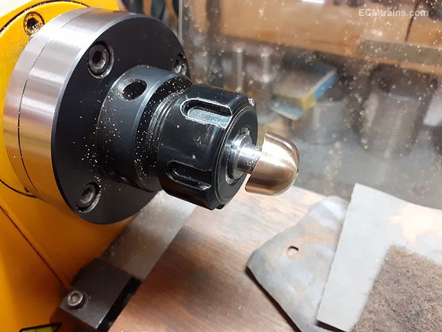
This is the tool setup for cutting the top curve, it's a Ball Turning Tool mounted in the toolpost with the cutting tool set to cut a 19mm radius curve, the lathe is run backwards in this set-up as the tool is cutting on the backface of the work.
Curve done, cleaned up with files and emery paper.
Test fit.
M4 brass screw fitted.
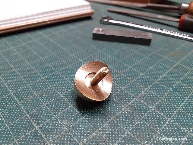
I engraved a bead line around the base of the dome with the point of a calliper/divider.
Then back into the chuck to turn down the M4 screw to imitate a top nut on the dome. The screw is Locktited in first!
Next the chimney, this is my setup for threading on the lathe, the slug is in the chuck after being drilled through, I disengage the drive motor, mount that handle to the left in the lathe mandrill and rotate the work with the aid of the handle while pushing the tailstock along the lathe bed- tapping the work.
Fly cutting the curve base of the chimney. The radius is 19.5mm.
The work is then drilled through with an 8mm drill. One has to have a hole in a chimney.....
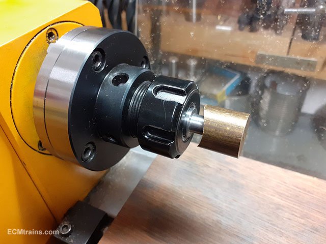
To turn the outside of the chimney the work is mounted on an expanding mandrel, it expands when tightened up and holds the work for light cuts.
Mounted in the chuck, the tail stock can be used here to support the work on the right but it gets in the way in what I'm doing, so light cuts are a must with so much overhang!
Rough cuts with a parting tool.
Finishing cuts with a round tool.
Filling down the sides, top one is done with the bottom yet to be.
Complete.
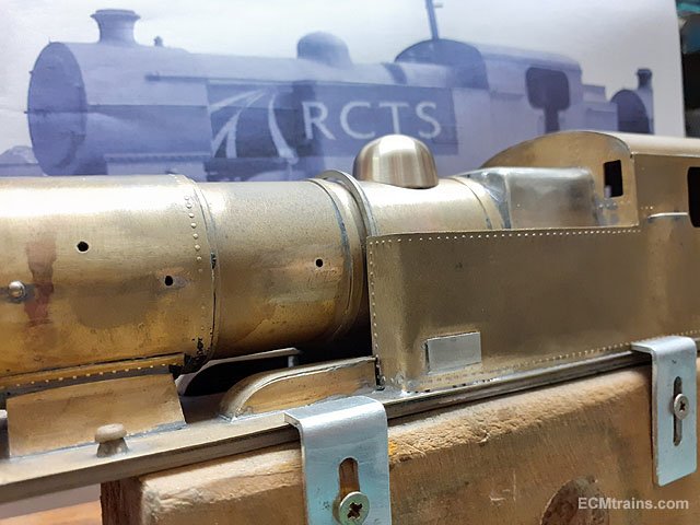
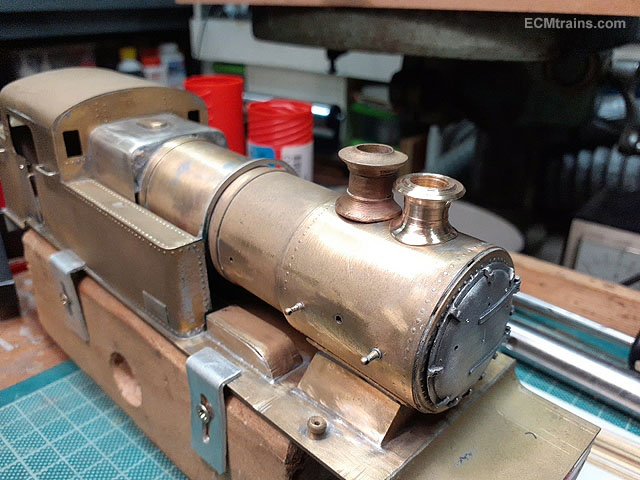
Test fit.....
.......and comparison with he one that was removed.
More later
Eoin
-
7
-
7
-
-
The Date For The July Fair;-
July 23, 2023.
-
1
-
-
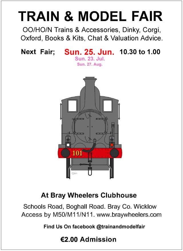
The date for the June Fair;-
-
4
-
-
Excellent stuff Ken.
Eoin
-
1
-
-
If the wheel sets have pinpoint axles? one could drill out the inside of the bogie frames and install brass pinpoint bearings......
Eoin
-
2
-
1
-


Bray Train & Model Fair
in What's On?
Posted
February Fair Date;-