

murrayec
-
Posts
2,571 -
Joined
-
Last visited
-
Days Won
67
Content Type
Profiles
Forums
Resource Library
Events
Gallery
Blogs
Store
Community Map
Posts posted by murrayec
-
-
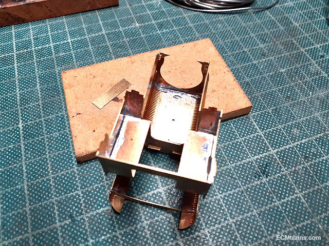
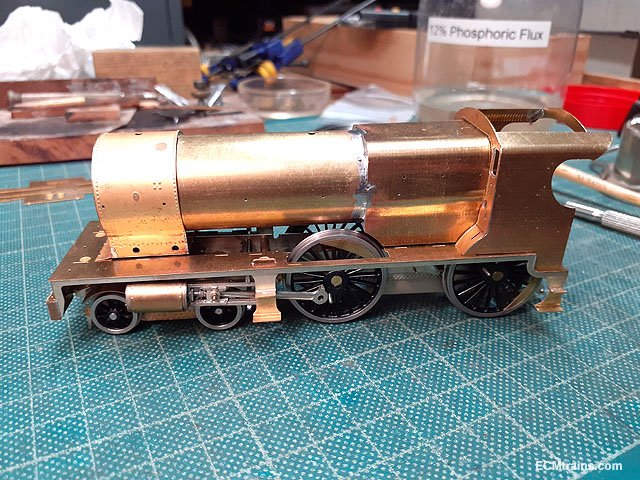
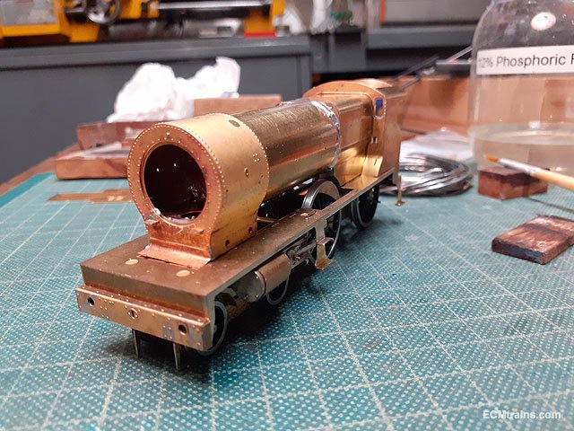
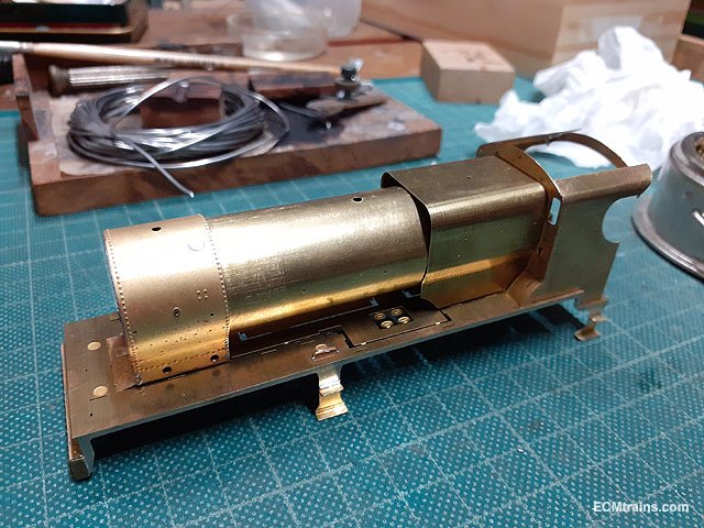
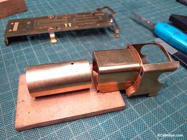
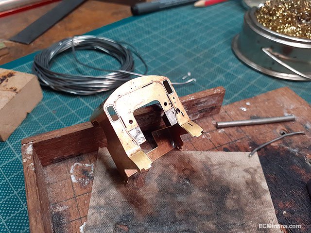
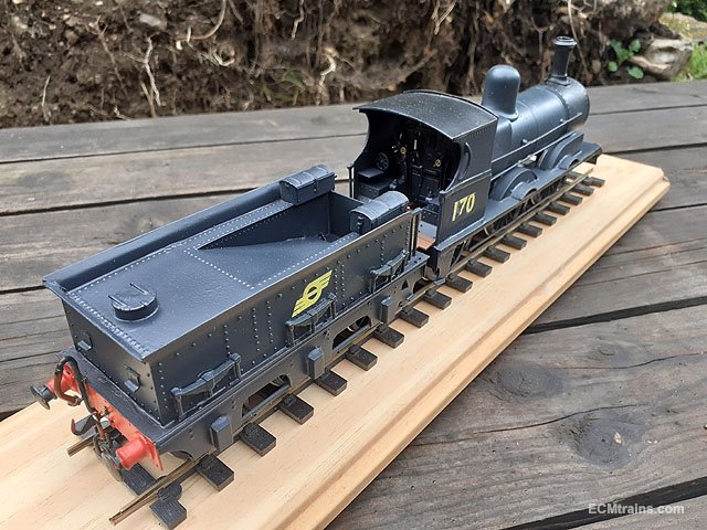
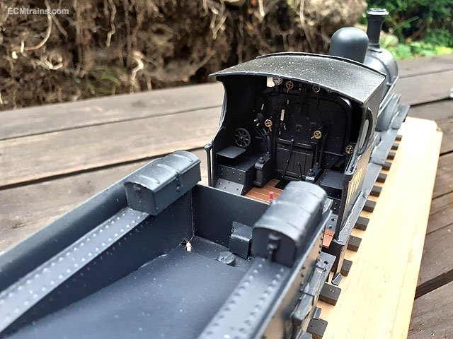
After a lot of fettling and trial fitting on the firebox cab end, then the boiler, smokebox and firebox were ready to be soldered together;-
First soldered in was the front plate to the fire box, soldered on the inside and then the construction piece at the base was removed.

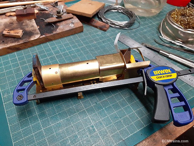
The smokebox was fitted to the running plate with a 10ba screw then the boiler fitted by tabs into the back of the firebox, and then the firebox & cab. The whole assembly was then clamped from back to front and adjusted to get it all to line up square- some paper shims were used between the firebox and cab join on the right side to aid alignment.
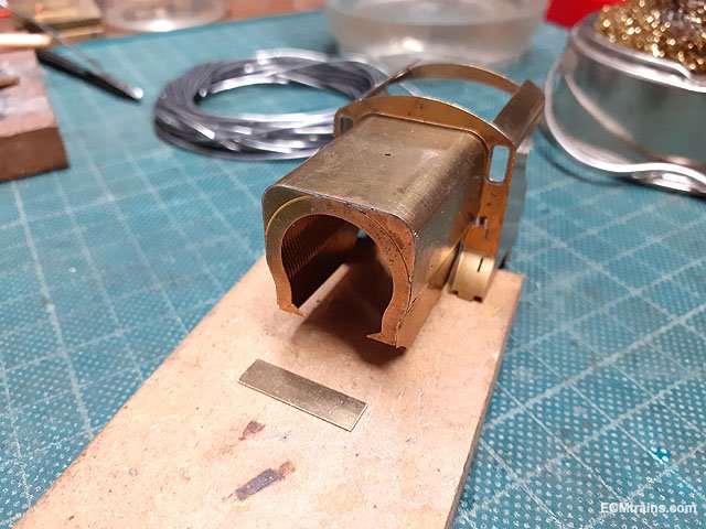
The join at boiler and firebox has to be soldered on the outside, tack soldered first and then soldered throughout. The other end is soldered through the smokebox- soldering the tabs on the inside.
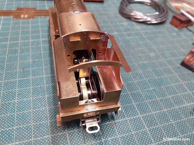
After the soldering was complete its now time to check fit the parts to the chassis and over the motor!! - after removing the fret in the middle of the running plate.
The running plate rear nut fixing is a good 1.5mm out of line with the captive screw in the chassis! So the plate does not sit down properly at the rear- this will need a bit of attention!!
The firebox slides over the motor OK but a bit of jiggery-poke is required to thread it over the flywheel as the firebox front plate is a tight squeeze on the weight- though it fits.
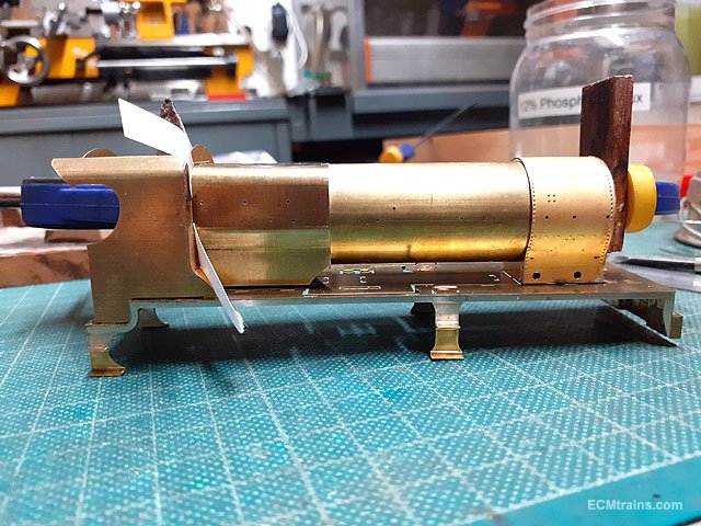
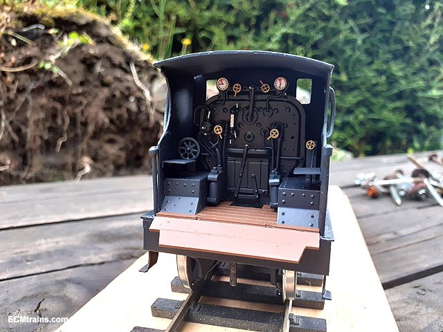
The boiler assembly needs a bit of a clean up and then the body detailing bits start.
Very satisfying to see it at this stage.......
Eoin
-
 5
5
-
 2
2
-
-
On 11/9/2021 at 10:20 PM, jhb171achill said:
........ A Ford "Thames" (or maybe VW?) ........
That looks like a Morris Cowley to me
Eoin
-
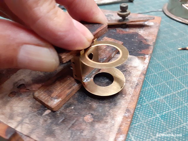
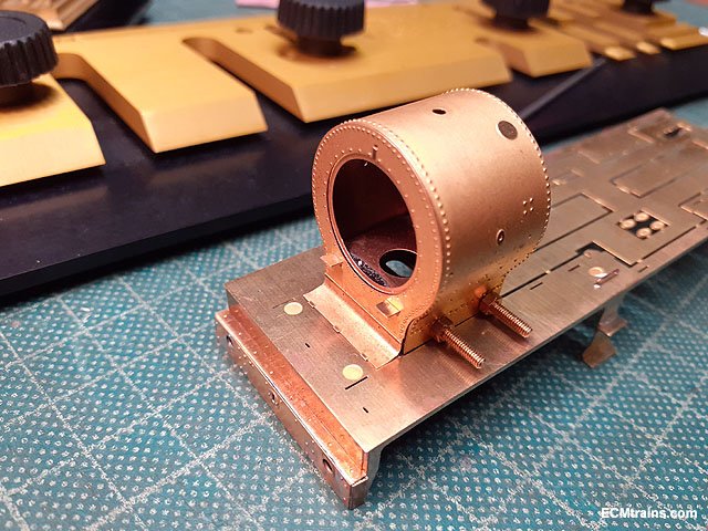
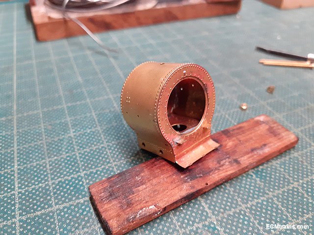
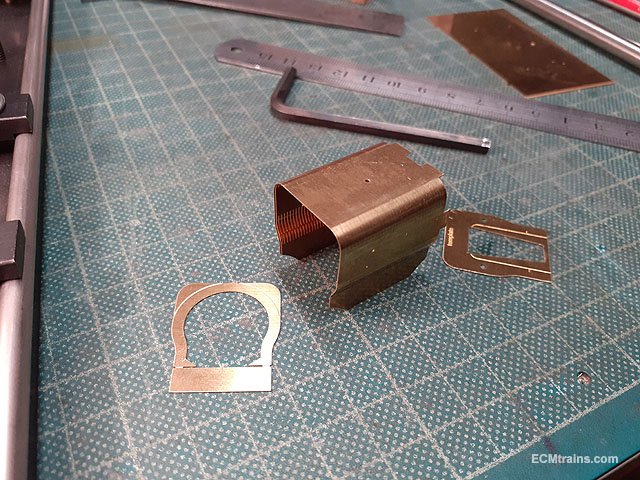
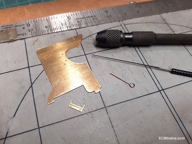
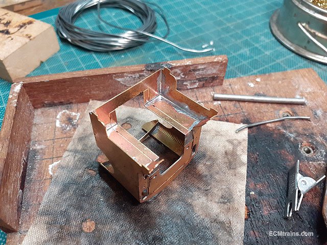
Smokebox;-
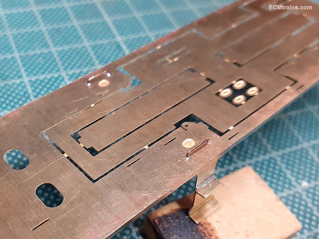
All the parts removed from fret and cleaned up.
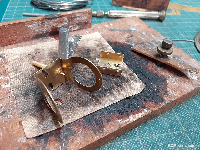
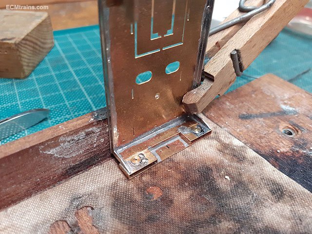
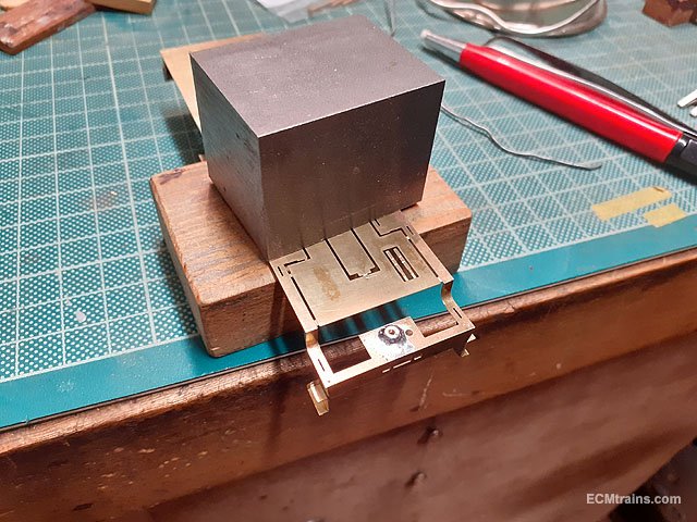
Main structure folded and ready to solder the captive nut on- this is the body to chassis mounting nut. The structure is partly folded as a stretcher part slots in after the nut is soldered, the stretcher has tabs front n back hence 'partly folded'.
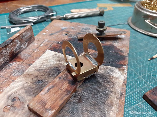
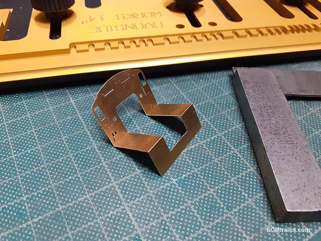
Nut soldered and stretcher in I soldered the sides first, if one was to force the front & back closed to solder first the base bows and the smokebox will not sit level on the footplate- so sides first.
Then front and back, ensuring they are perpendicular to the base.
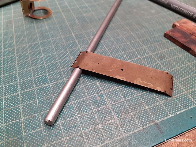
The reverse curves on the wrapper are bent over a 6mm rod to the rough shape.
The wrapper was then curved over a 16mm rod and then bolted to the main structure with 10BA bolts- the bolts pull the wrapper in at the bottom, the shape can be assessed while doing this and adjustments can be made by removing the bolts- I like this idea.
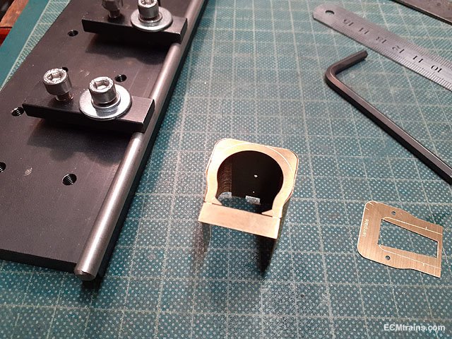
The base of the smokebox front needs a 2mm dia curve outwards which slots into a half etched recess in the running plate, this was a bit tricky getting things to line up- the curve starts just under the holes for the front grab rail.
Just a test fit before I start soldering.
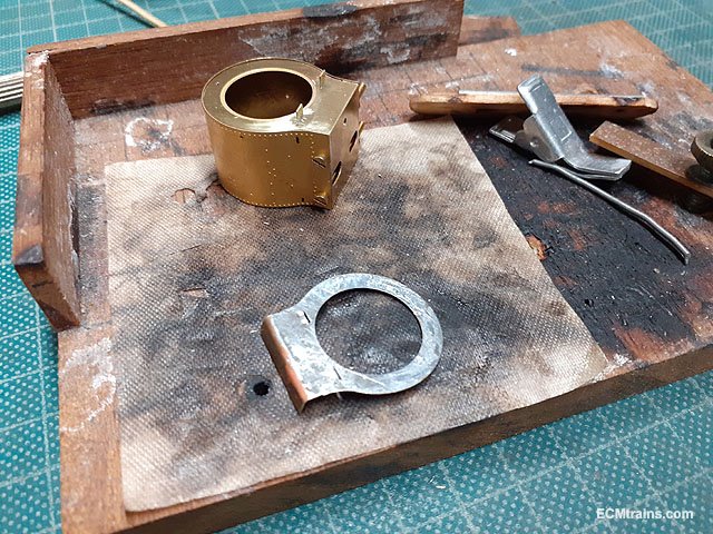
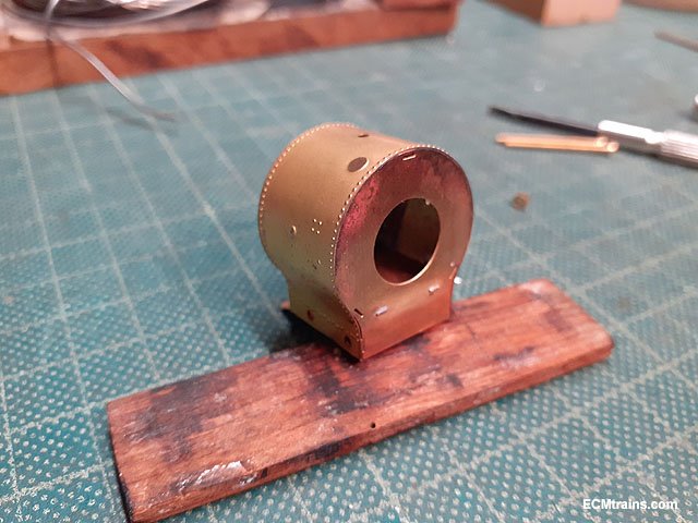
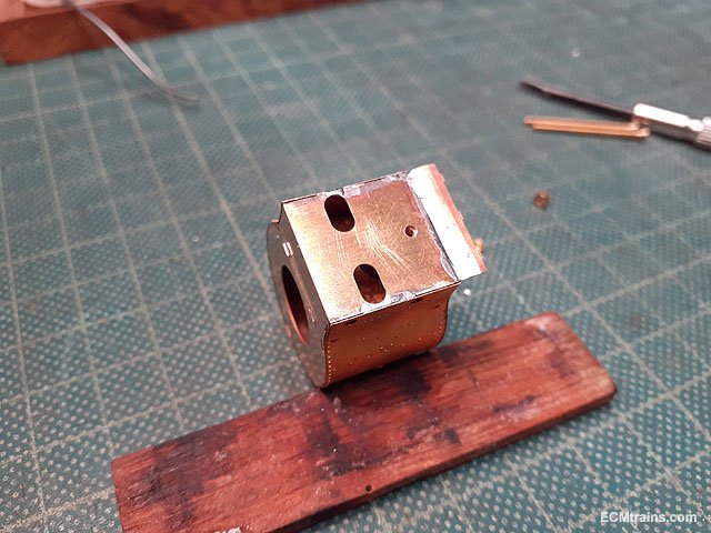
The unit will be soldered on the inside through the holes front and back, the front cover will go on at the same time while soldering on the inside so the front has solder applied to the back face in readiness.
Some pushing and clamping was required to get the return curves up tight to the structure, working on short sections at a time, moving to the other end alternately until the unit was soldered up- reward! = burnt fingers!
Needs a bit of a cleanup and maybe a few soldering touch ups at front bottom sides!
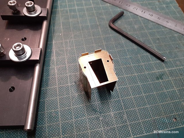
Joy rigged on the running plate to assess fit.
A bit of fettling to the firebox junction with the cab is required and then I reckon the smokebox, boiler and firebox can be soldered into one unit!!
Eoin
-
6
-
1
-
-
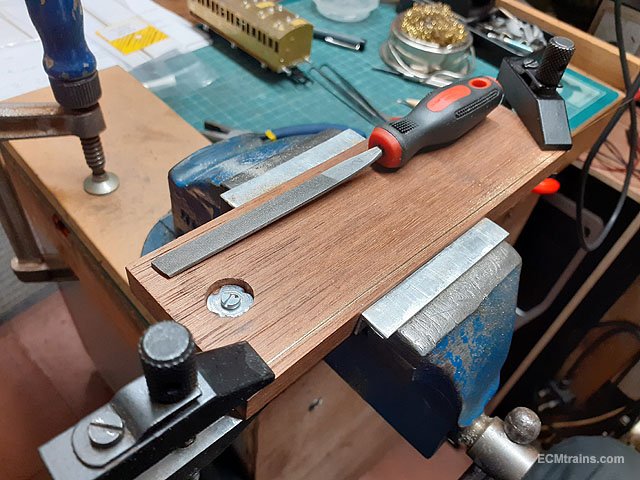
Hi JB,
Expo tools;- https://www.expotools.com/index.html
All manner of tools, clamps n vices, and materials
The website has the whole catalogue but it can be hard to find specific items so if you order from them buy the printed catalogue which makes things easier.
Eoin
-
3
-
-
I believe Robert is correct here ''less is definitely more'' I also trialled with this and after several goes came up with .7mm packing under the outside rail and the points, worked best....
Eoin
-
 1
1
-
-
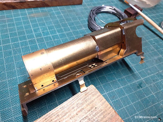
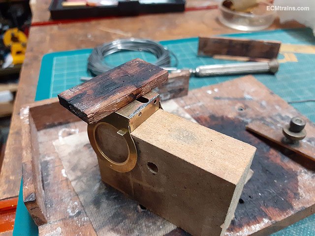
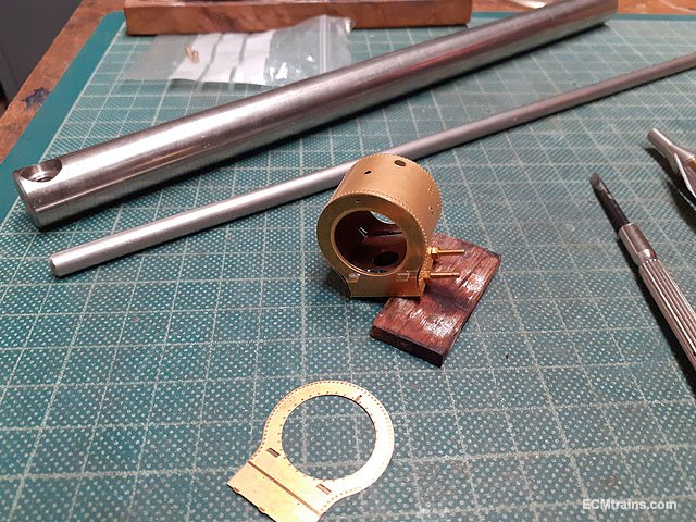
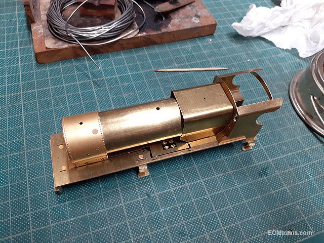
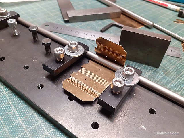
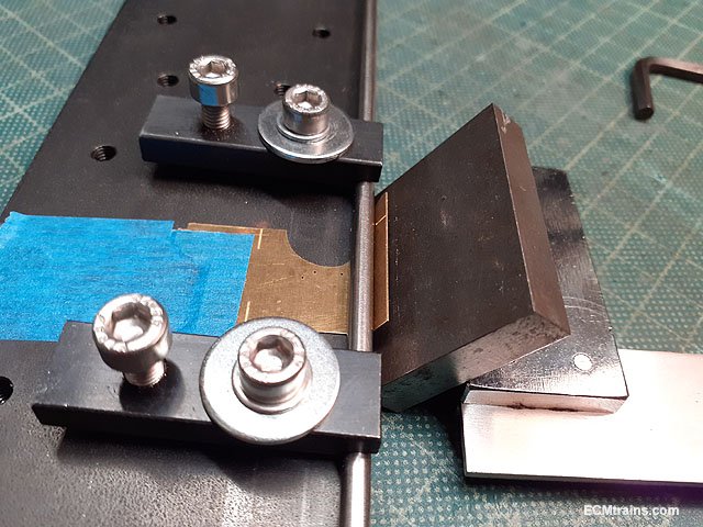
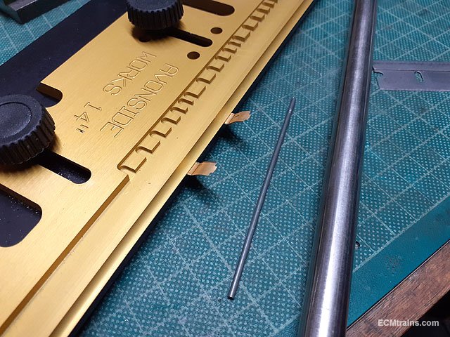
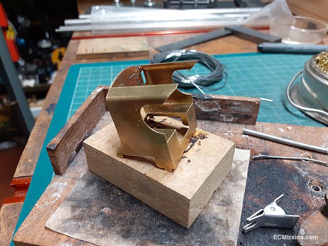
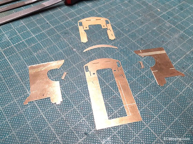
Boiler & Belpaire Firebox;-
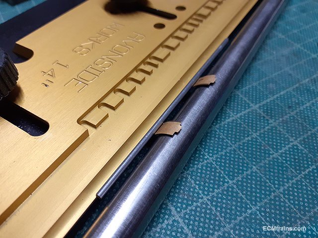
Clean up of the parts, drilling holes for ejector piping in boiler and to mark the location of the firebox stay covers- Merlin has 3 on both sides.
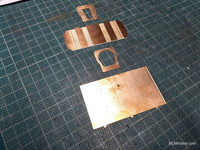
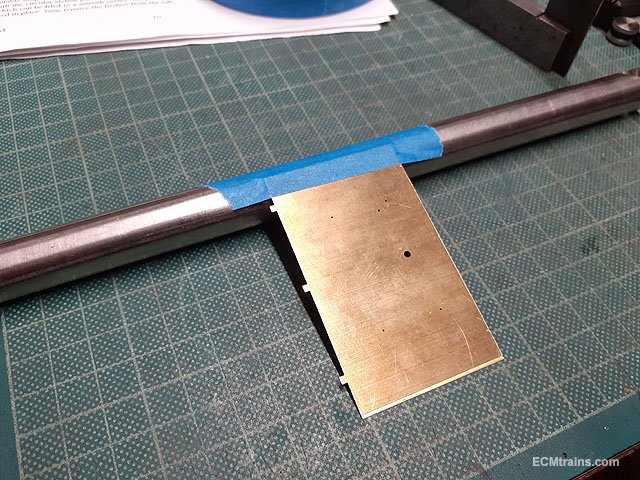
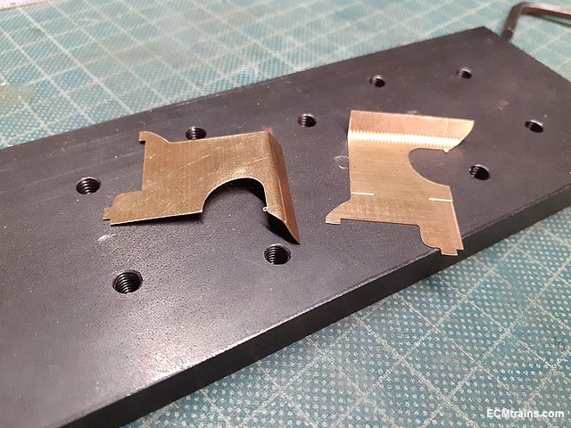
After measuring up the firebox plate I found the half etch relieving lines for the folds were bang on! So I set about folding the lower curves first using 4mm and 6mm here.
Top curves were done with the 6mm bar.
Folded.
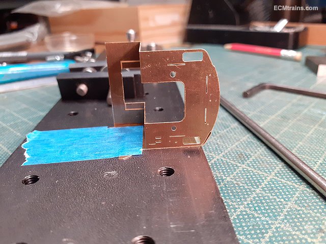
Checking the fit on the front plate and the back template- the template is only for construction.
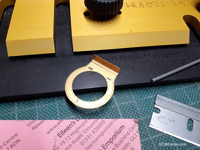
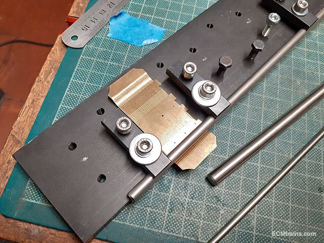
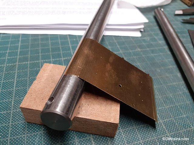
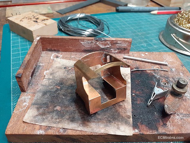
I started the rolling of the boiler on a 16mm bar in the bench vice, taping the sheet down square on the bar first.
Both ends done.
Then rolled the sheet to size.
This was far enough.
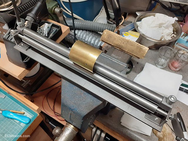
Binding with rusty binding wire- solder wont take to rust, so I keep roll of rusty wire for this! The clamps held the join in position while tightening the wire. The soldering is done on the inside of the join with the part held in the fingers to put pressure on the tube to ensure a good join- using wood between the part and the fingers.
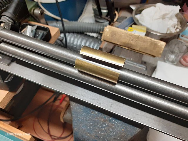
Soldered up on the inside.
A bit of fettling is required to fit the firebox square to the cab.
Next will be the stay covers onto the firebox and I will assemble the smokebox parts before soldering all up- just in case some adjustments are required.
Eoin
-
6
-
1
-
-
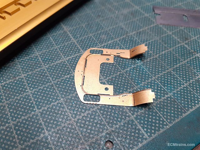
Continuing on with the cab;-
The holes for the cab side wind deflectors are drilled 3.5mm and broached to take 3.7mm pins to imitate bolt heads, all other holes in the cab parts are also broached to this size. The deflectors will be soldered on at a later stage as they will be in the way while clamping and soldering the cab structure.
The inner cab part is folded up to form the splasher tops and backs.
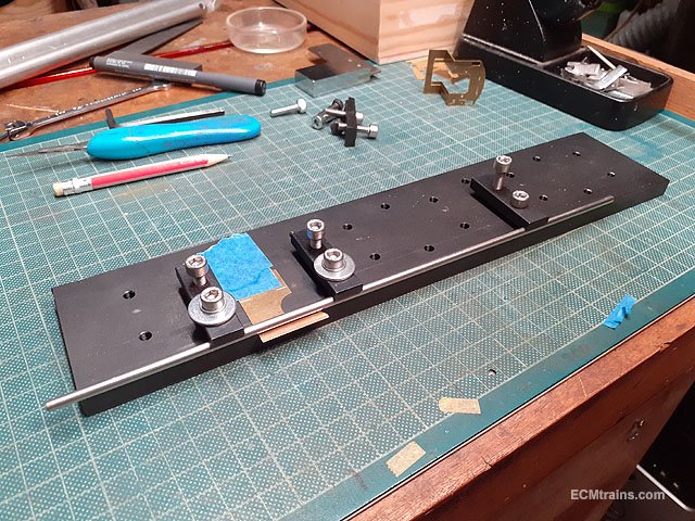
The cab sides are jigged up for folding the roof curve.
Once in the correct position the top portion is folded with a flat piece of metal up to about 45 Deg.
Checking for fit on the cab front, the tape is there to hold the part in position just in case it needs to be re-jigged and folded a bit more. This is fine, a bit of pressure on the roof portion will push it home when soldering.
Both sides done.
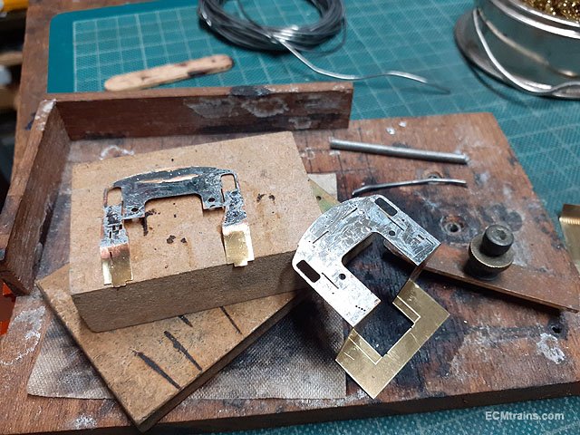
The front cab overlay forms the front of the wheel splashers so I decided to get rough folds in it to make the soldering job a bit easier.
After setting the correct location the part was clamped, a 2mm bar to create the turn out was held on top, then a 12mm bar was slid in under, and the part was folded over to give the rough shape.
The inner cab and overlay parts are prepared to sweat solder them together. A light coat of solder was applied as these parts form a rebate on the edges for the cab sides and roof to sit into- to much solder would fill the rebate!
This was the clamping arrangement after lining up the parts through some of the 3.7mm holes with pins, as the soldering progresses the clamps are removed while applying pressure with a stick to ensure the parts fit snug together.
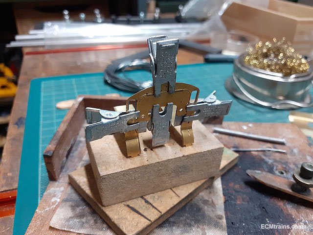
Sides tack soldered on and all is checked with a square.
Then the roof rib is soldered in and the whole assembly is soldered up.
The wheel splasher fronts are adjusted slightly and held down with a stick while soldering to the cab side that forms the splasher sides. The pre-folding was pretty close but a lot of pressure was needed to get a good fit.
Testing on the footplate..... it fits!
Eoin
-
2
-
-
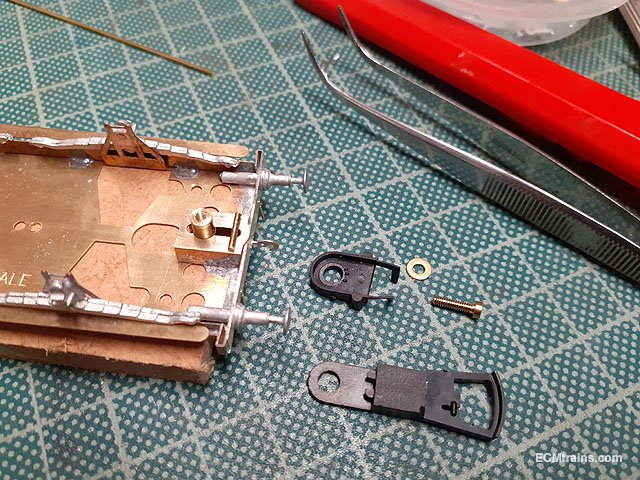
8 hours ago, popeye said:
Sometimes I cut the coupling where the red line is in the picture and make a
new hole where the red spot is. It might keep it away from the axle.
I use different methods depending on how much room I have.
That's most likely what I will do, with the new mounting plate and a new hole as you suggest keeps the coupler away from hitting the bogie.
Eoin
-
1
-
-
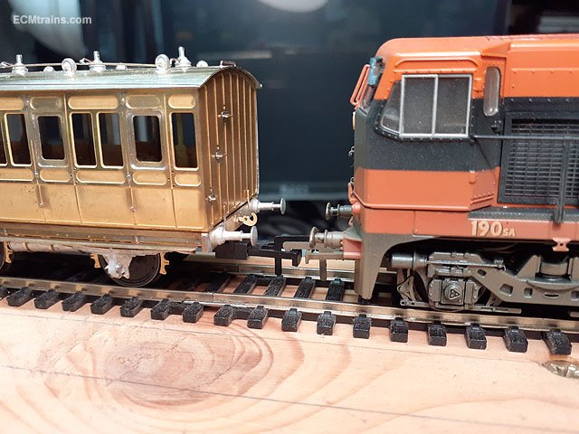
3 minutes ago, popeye said:
I usually keep my couplers nearly level with the buffers and they work fine, it also
keeps everything close together.

Yes, the coach in the photos was the first attempt on positioning the couplers. I have now cnc'd out a revised brass mounting bracket to pull the couplers back in closer to the buffer line- though the Dapol assembly conflicts with the bogie frames now! so the second coach at this stage of the build is the test bed to come up with a solution......
Eoin
-
2
-
-
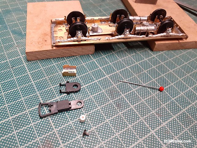
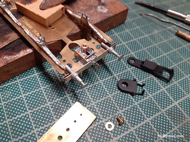
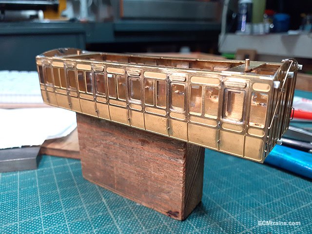
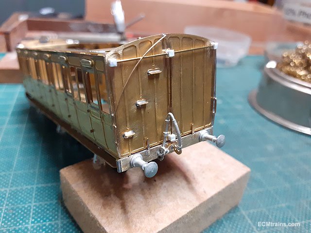
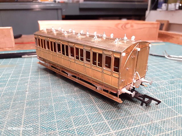
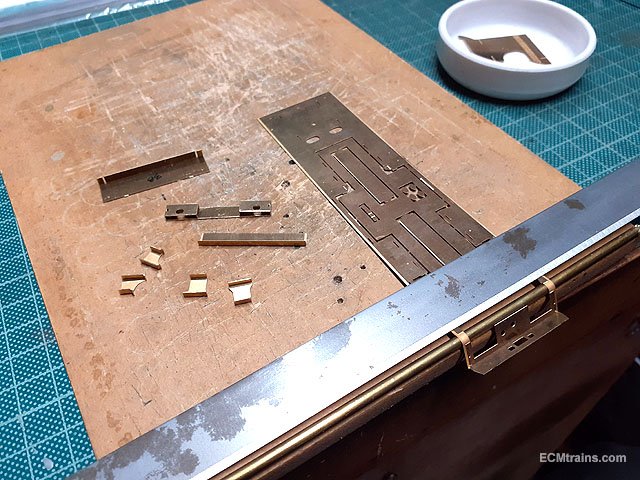
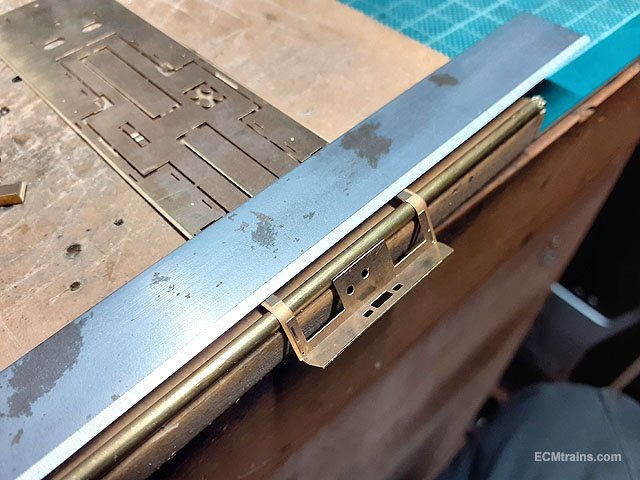
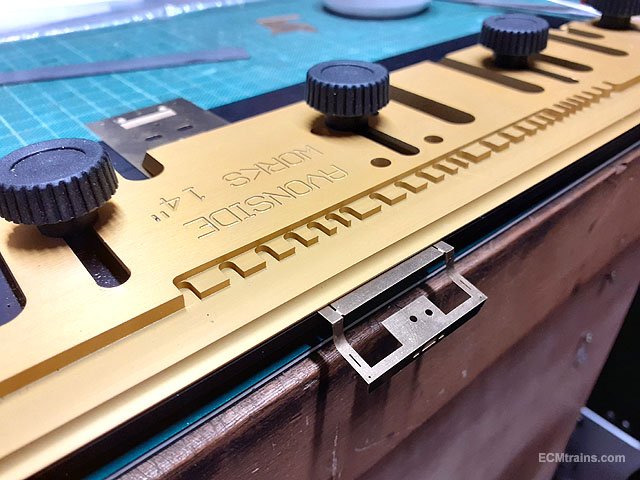
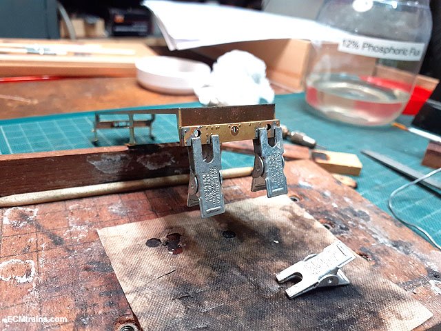
Chassis & body brass work coming to completion;-
Setting up to install Dapol NEM pocket fittings, the chassis mounting part is folded up and a 3.15mm styrene mounting spigot prepared to joy rig the pocket to access the correct level and decide what mods are needed.
The drag beam overlay parts, buffers, vac pipes and hooks are prepared for soldering.
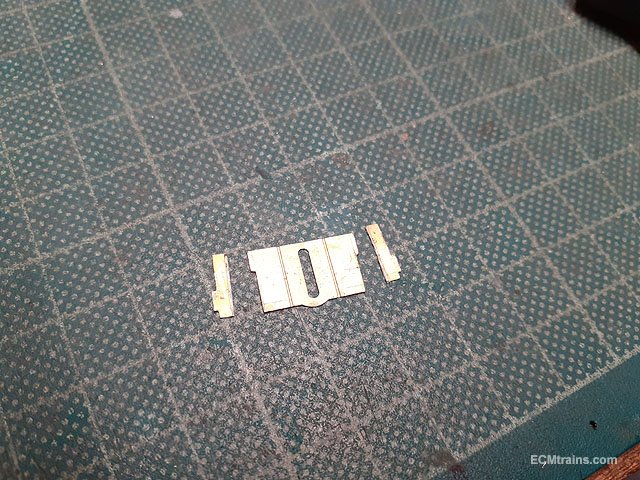
After assessing the coupler height this is the mod done to the mounting plate- 3.4mm cut off the upstands to set the correct coupler level.
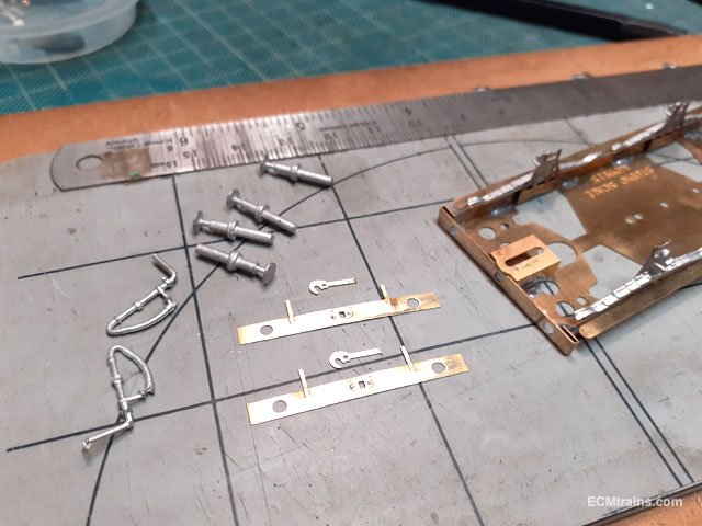
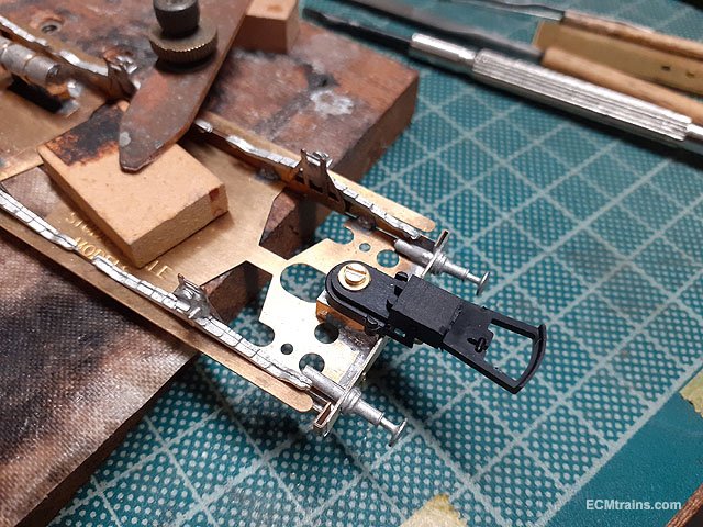
After the drag beam detail overlay, the buffers, the hook, and the modified plate are soldered on, a brass 3.15mm spigot tapped 10BA to mount the coupler and a 1mm wire stop to hold the Dapol spring plate on centre were made up.
Parts soldered on and a 10BA screw prepared for the fixing.
Mounted.
Verified.
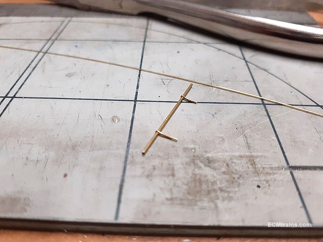
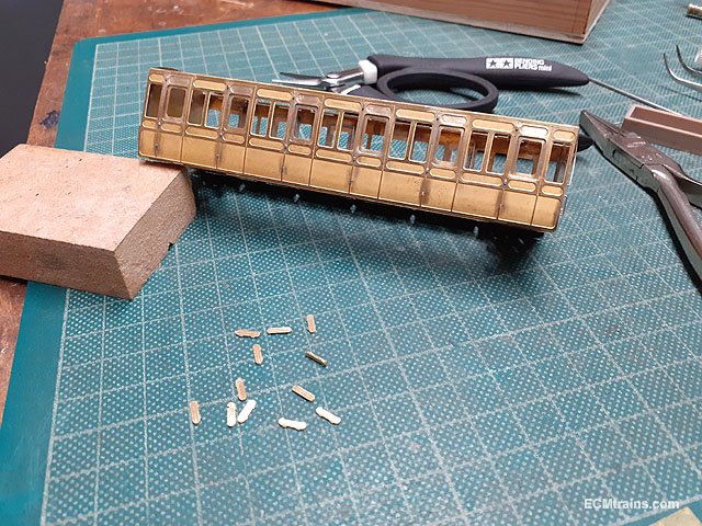
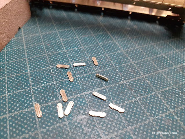
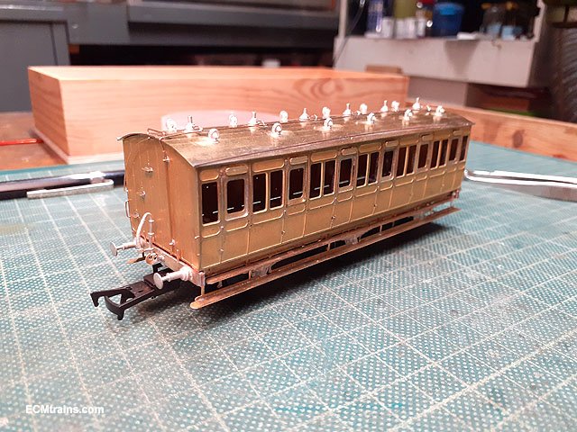
The gas light roof pipe was next- to keep the roof removable the pipe needs to separate from the end down pipe so I decided to use a .4mm bore pipe to do this. The pipe is held with two .3mm split pins soldered on the coach end, so I made up a batch of pins by half filing .3mm brass wire n folding over to create the pins.
Pins fitted to the down pipe, which will thread through .4mm holes drilled in the end plate and soldered on the inside.
Gas down pipe and end handrails ready to be soldered on.
Done. The solder wicked through the split pins and soldered the pipe in the pin heads.
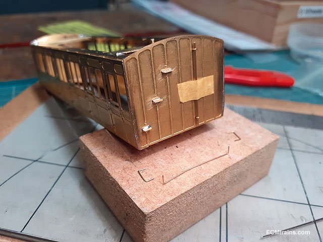
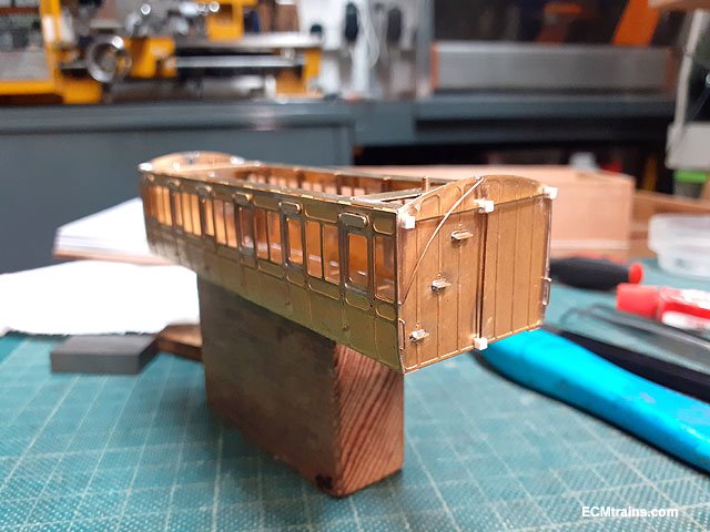
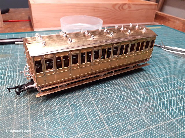
Next is the coach air vents, these parts are folded and stuck in place with epoxy glue.
After folding, the parts need a rub with a file to remove the fret part which helps the folding process but leaves tabs on the top edge.
Stuck on.
Emergency brake parts are stuck on with epoxy glue also.
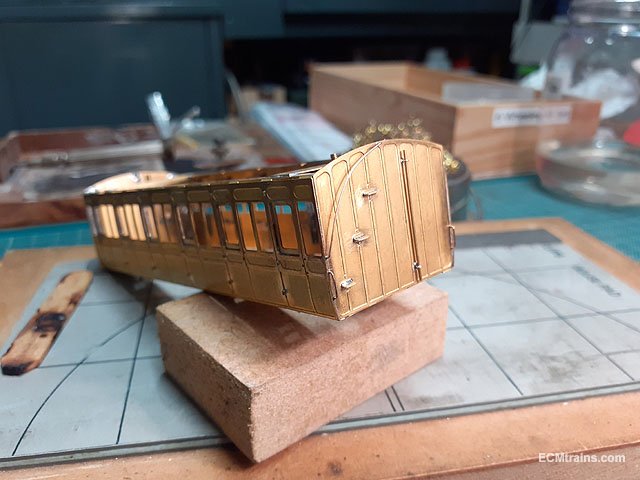
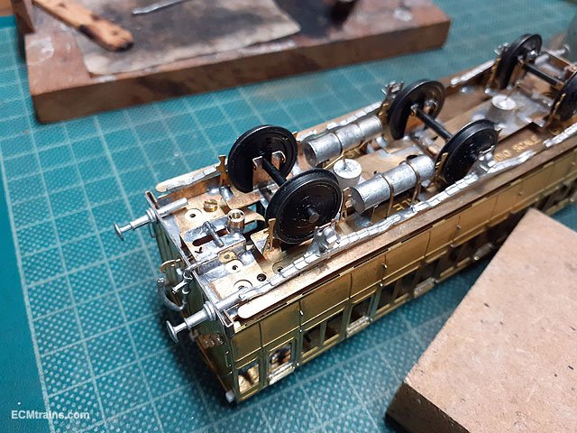
The vac pipes are now soldered on with 70deg solder to the side of the coupler chassis bracket. The upstand pipe is supposed to lean over like that!
And finally the last parts to the chassis- the lower side step/running boards.
That completes the chassis and roof which are now ready to start painting. The body requires the internal partitions and then its ready for painting also.
Two of the four coaches are at this stage..... another two to go!!
Eoin
-
12
-
2
-
-
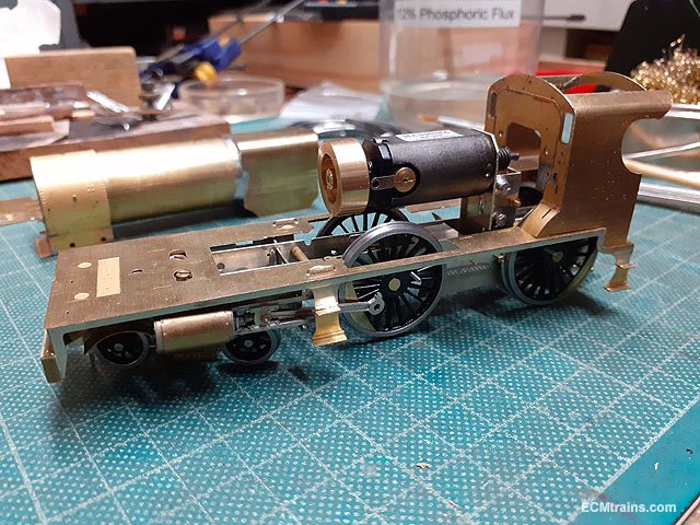
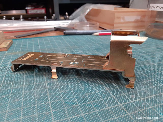
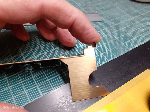
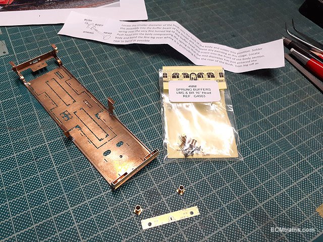
Footplate, buffer beam and steps being folded up and getting ready to solder.
The footplate cab end drag beam is folded down, then the curve is folded over a 3.15mm dia brass rod.
Then the 90 deg bend is folded down.
Checking the folds with the cab side and making adjustments.
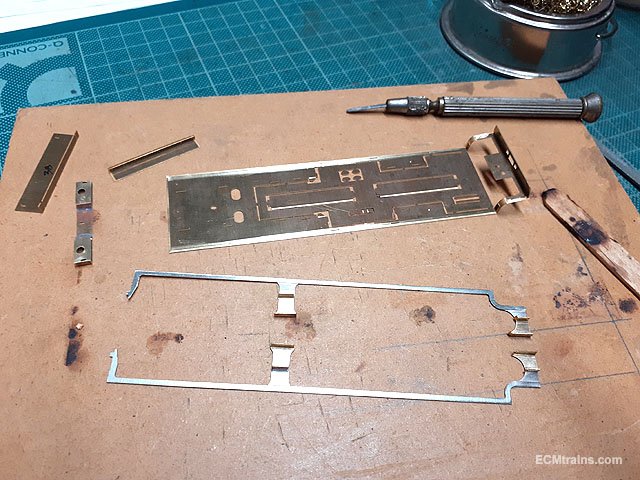
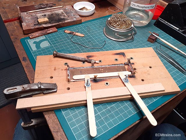
The folded up steps are sweat soldered onto the valances, the front buffer beam structure is also soldered and all is ready to tack solder together! But the jig part 38 (top far left in the photo), is supplied in the kit to hold the valances at the front while soldering them to the underside of the footplate, doesn't fit! So have to do it by eye.
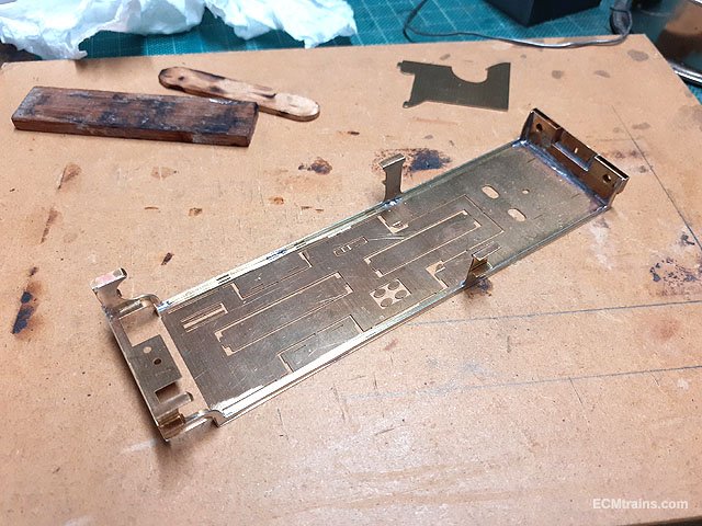
All tacked in place with some minor adjustments at the drag beam end.
Next is the detail etch cover to the buffer beam, but before soldering it on I decided to look at the buffers to see if any adjustments are needed. The fact that the buffer beam structure is a box type affair the buffer bushes at the back are not long enough to support the spring and keep the buffers out where they should be! Easily remedied with a brass tube spacer behind the spring on final assembly.
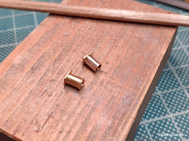
The buffer shanks have a rib on the end which needs to be filed down, one is done in the photo.
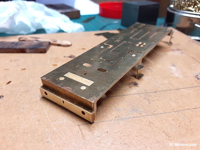
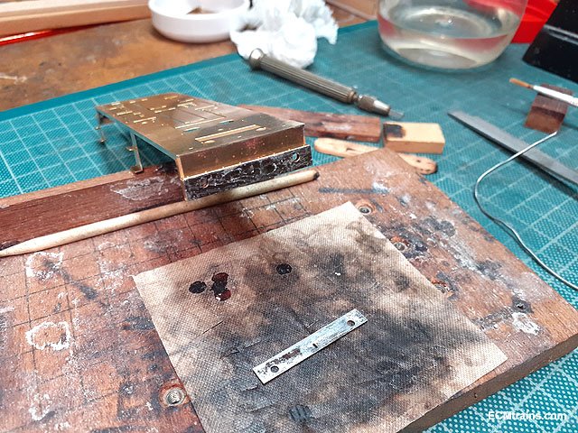
So after checking the buffer fit and making adjustments the whole footplate was soldered up.
Then the buffer detail was sweat soldered on.
The buffer bushes soldered into the rear of the beam structure.
The rear chassis fixing captive nut was soldered on.
And the front steps grab handles soldered in.
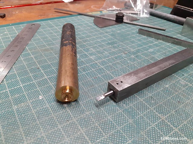
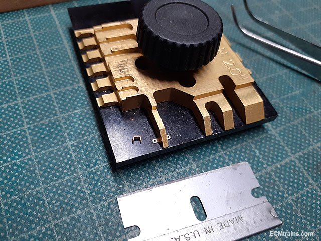
Now a bit of turning- a 16mm dia brass flywheel for the motor, flywheels like all their weight on the outside of rotation for maximum torque, so a grove needs to be cut in the front face. This is done on the lathe which is called 'trapanning' - cutting a recess in the end of a bar. A tool 3mm wide was ground to shape for doing this which is on the right of the bar stock.
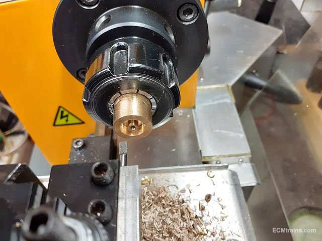
Stock cleaned up in the lathe, drilled 1.9mm for the 2mm motor shaft which will be reamed 2mm after the part is parted off as this is not a through hole and cant be reamed here. The trapanning was done leaving a 1mm collar at the motor shaft, very slow speed, loads of lube, and slow feed into the work does the job.
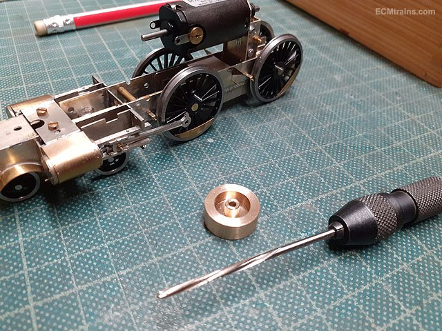
Parted off at a depth of 6mm, cleaned up and reamed 2mm......
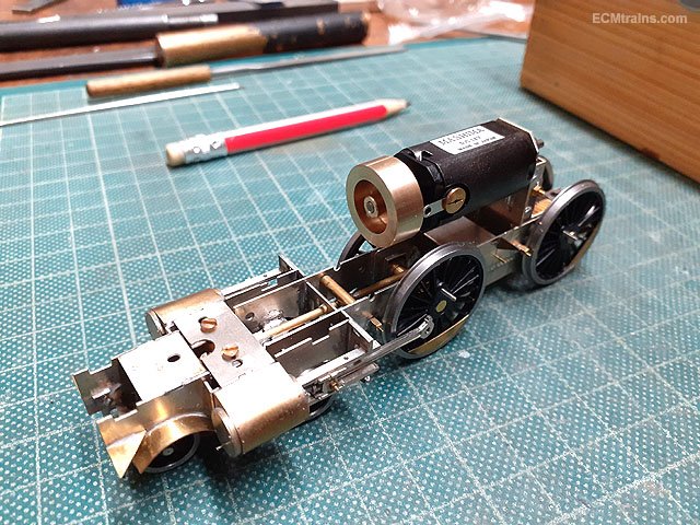
and test fitted, which will be Locktited on final assembly.
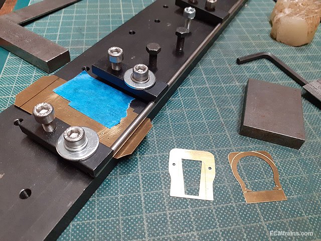
Next up are some cab parts, cut from the fret, de-cusped and ready.........
........that will be later.
Eoin
-
8
-
-
Next months Fair date is the 5th September;-

-
2
-
-
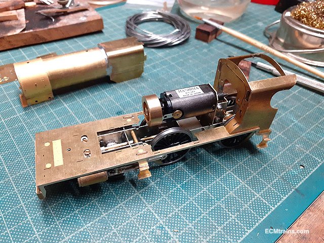
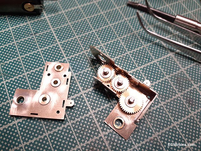
The gearbox & Motor is next, so that I can work out the space I have for the electrical pickup system under the ashpan!
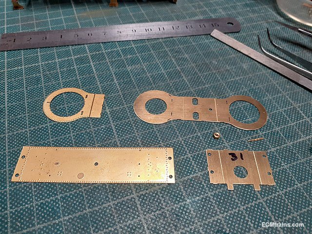
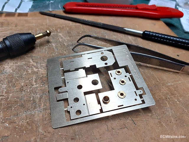
The gearbox bearing holes are sized while the parts are held in the fret.
The drive axle bearings are filed down so that they only protrude .5mm outside of the gearbox.
All folded, 2mm lay shafts cut ready to solder into the bearings. I soldered the bearings into the gearbox frame first (the folded bit), dry fitted the shafts and gears in that side, then checked the fit of the gearbox cover with loose bearings to see if all works OK. It goes together fine but the gear under the worm has to much side play so washers will be fitted on final assembly.
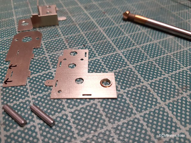
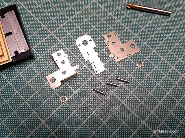
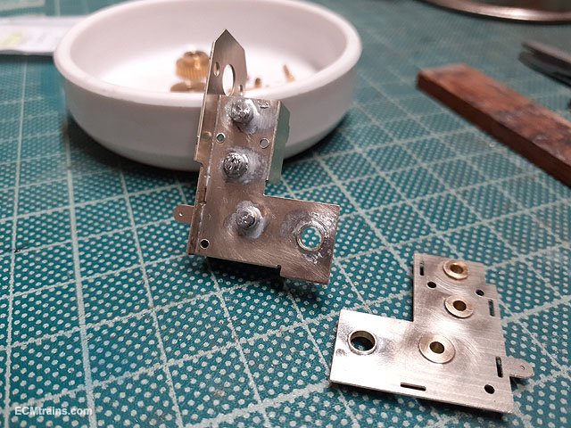
Then the cover bearings and the gear shafts are soldered in- the shafts are soldered into the gearbox frame bearings only.
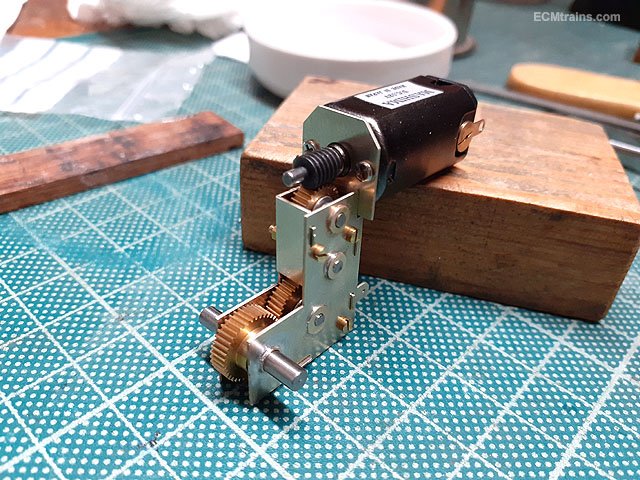
3 no. 10BA bolts n nuts are used to assemble the gearbox and then the drive axle bearings were soldered in using a 1/8'' aluminium dummy axle to check alignment and solder wont stick to aluminium, the drive axle gear also requires a washer to be installed to take up side play.
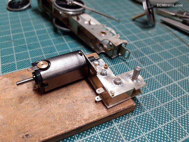
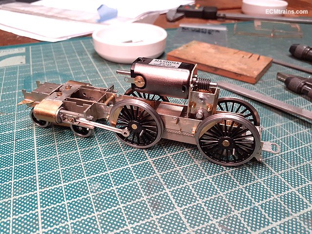
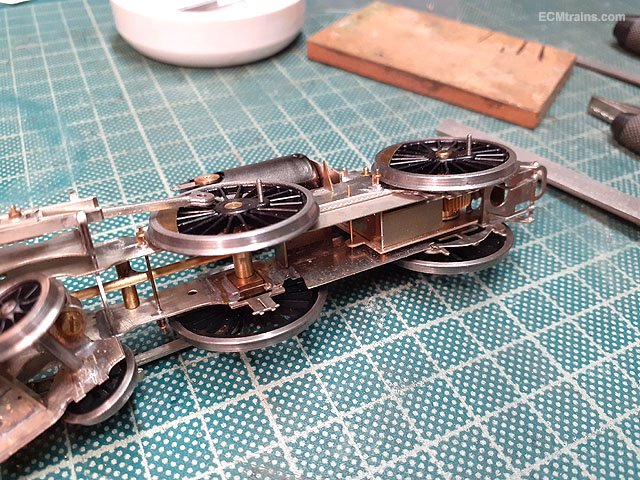
When fitting the unit to the chassis the lower gear shaft, bearing and BA bolt end had to be filed back to stop it fouling the ashpan inside the frame.
Fitted.
Now I can see what I have to play with for the pickups......
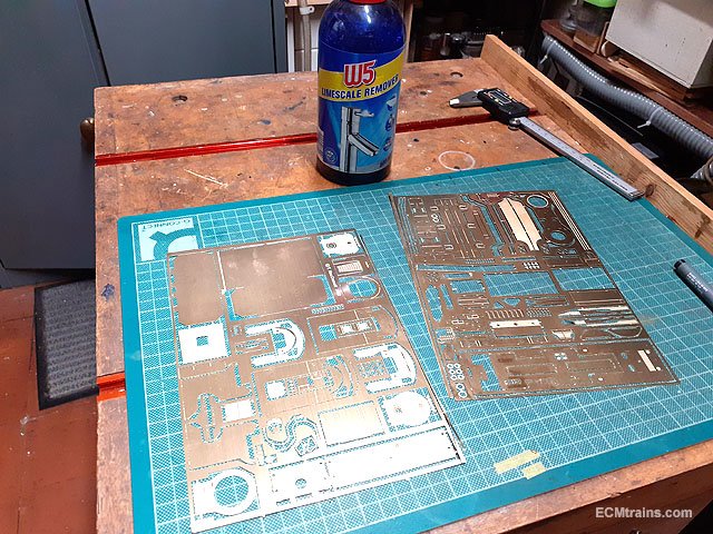
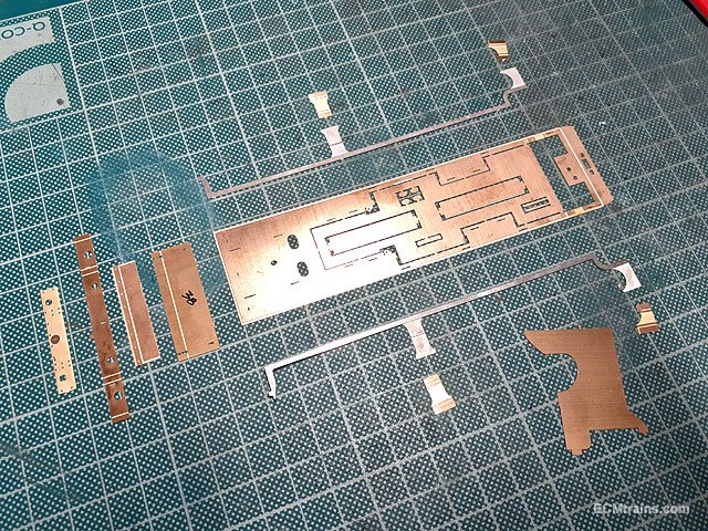
Next up is starting on the loco body, but first the etches, which were heavily tarnished were cleaned up with W5.
Footplate parts cut out and yet to be de-cusped, folded and soldered.
Thats for next time.......
Eoin.
-
6
-
2
-
-
It looks like the track on the points could be trimmed back to the board edge and then use the same sleeper connection unit to the track on the adjoining board to butt up against the trimmed points track??
Eoin
-
@gm171 kk Here is a link to my version of the coper clad sleeper baseboard junction, ignore my plug in track section that covers the board joins for your purpose- it's like George's example! the sleepers are screwed down at each side with Peco track screws to the edge of the boards, track is soldered across and then the track is cut.
Eoin
-
One of the best accessories for controlling light for photography are reflectors & diffusers, which are not to expensive, there is a range but one white reflector & diffuser can be a great assistance to control those hard shadows and soften the intensity of the room lights......
Eoin
-
4
-
-
Next Fair Date Sunday 8th August;-
If you would like to view photos of the traders tables on facebook click on the poster above.
-
You Could;-
Try another DCC chip in the tender.
Try running it on a friends DCC system.
Remove the chip and test the loco&tender on an analogue track- you will need a blanking plate in place of the chip to do this!
If you recently had the chip out or just installed it- Check the chip is plugged in the right way around.
Check that there is no wheel shorting somehow- use a multimeter continuity test to do this.
Check the pins on the socket between the tender and loco- that none are missing or bent and causing a short.
Eoin
-
1
-
-
KMCE has scratch built the armoured tank loco and the full train in 4mm 21mm gauge;-
https://irishrailwaymodeller.com/topic/7108-kmces-workbench/page/3/#elControls_125194_menu
One could be lucky to see this in the real if he comes to the Train & Model fair tomorrow??
Eoin
-
2
-
-
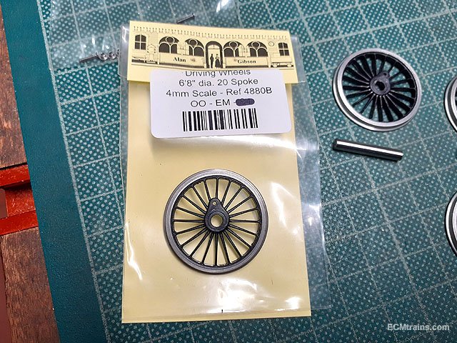
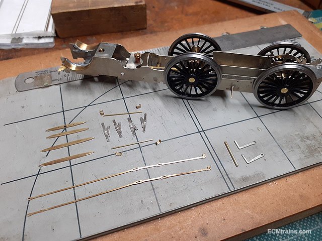
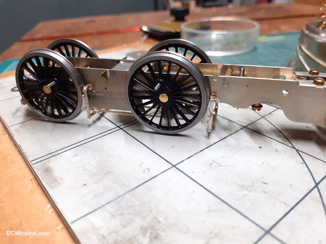
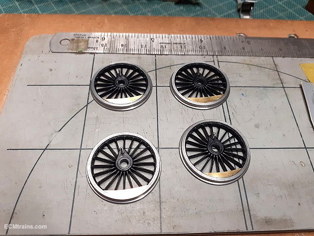
After getting the replacement wheels I decided to finish off the chassis bits before doing the gearbox & motor!
The right wheels this time, I got them from Alan Gibson in the end- after weeks of telephoning and just getting the answering machine.....
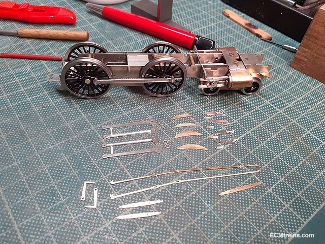
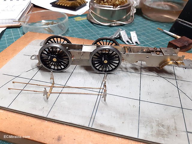
The crankpin BA screws were installed, all was assembled and wheels quartered to broach the coupling rods for free running. In the foreground is the brake parts, connecting rods & wheel weights all cleaned up, holes sized and ready for folding/soldering.
Connecting rods and brake shoes folded/soldered, yet to be cleaned up.
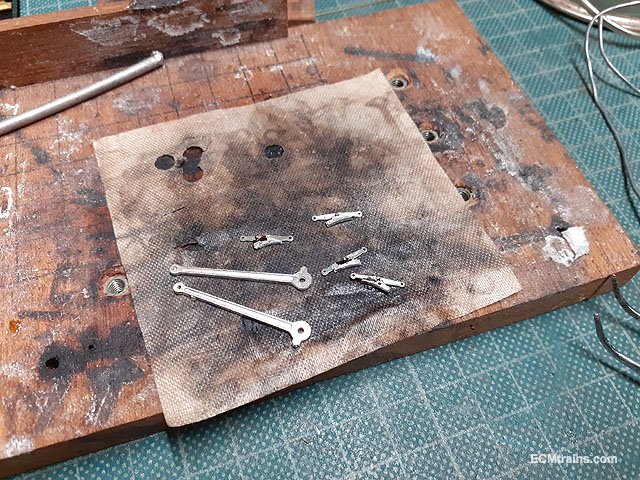
These are the break hanger brackets being folded up. Their threaded onto the .5mm wire pins through the chassis for hanging the brakes off.
Now to solder them on to the chassis.
The rear brake frame bracket are fitted onto a .9mm brass wire through the chassis brackets, I left the brackets free on the rod to be soldered when the brake pull rods are on for positioning.
.5mm wire pins soldered through the chassis frames with the little spacer brackets threaded on and soldered.
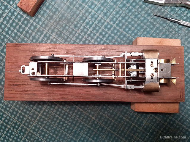
Next the shoes, pull rods and beams were joy rigged in place and soldered up- very fiddly as one wants no contact between the shoes n wheels which will cause a electrical short. Those rear brackets are now soldered to the .9mm brass pin. The back end of the pull rods and the top of the shoe hangers are not soldered so that the assembly can be removed.
And removed.
Wheel weights being epoxied on.
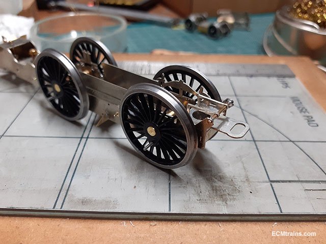
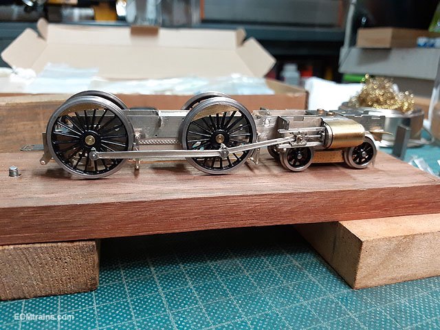
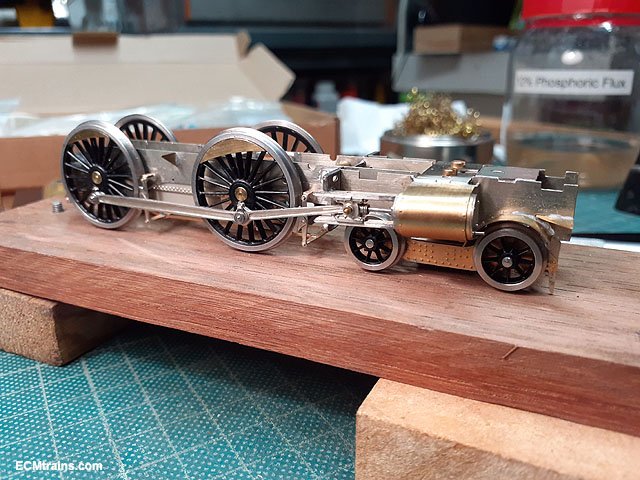
The connecting rods were cleaned up and the crankpin end generously broached as these will be at quite an angle out to the crosshead. Wheels back on and time to assemble the gear.
Assembled.
The connecting rods are at a crazy angle, causing binding on the crankpin bearing and the coupling rod, the bearing is not long enough, which also needs a washer and a bit of free space for this angle. I'll make up a bearing to suit.
Eoin
-
9
-
-
2 hours ago, Haulier said:
Would old WTT/TT's, etc be on sale at the BRAY T&M Fair ?
Not really stuff the traders carry! ask wrennie on this forum he may be able to help!! @WRENNEIRE
Eoin
-
@Georgeconna Patios! - on the 'bright side' their great for all sorts of projects! wood work and metal work which is to messy or to big for in the workshop.... every modeller should have one!
I hope that helps?
Eoin
-
1
-
-
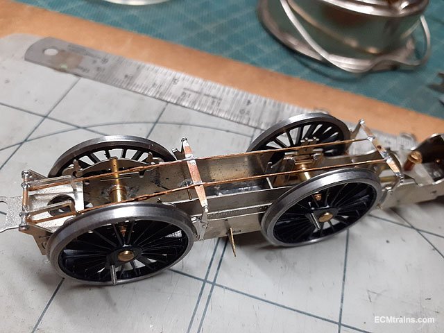
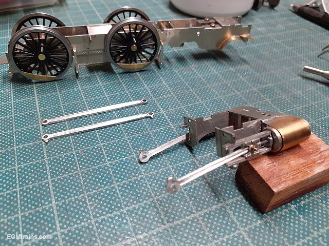
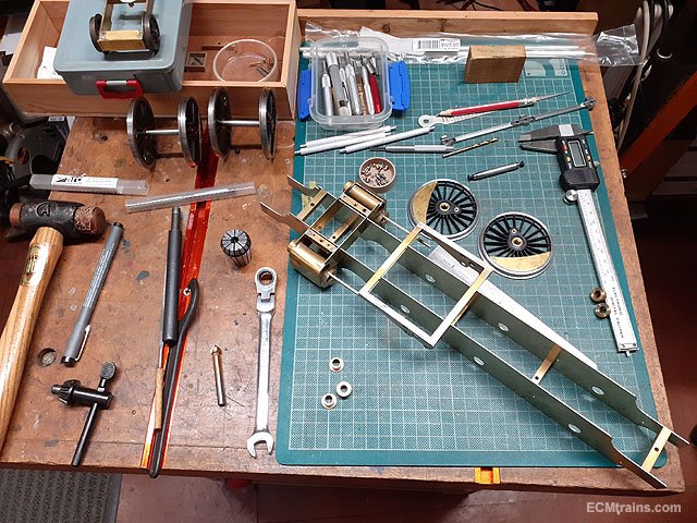
Time to fit the coupling rods and set up the chassis so that final dimensions can be set for the drive rods and crossheads to be made.
First though, as mentioned above the chassis is a bit fat and the wheels lock on the axle bearings when bolted up! So a 1mm shaving was taken off the face of all the bearings.
Bearings faced and then a set of axle jigs was turned up from 1/8'' aluminium rod to set the bearing centres while soldering them into the frames.
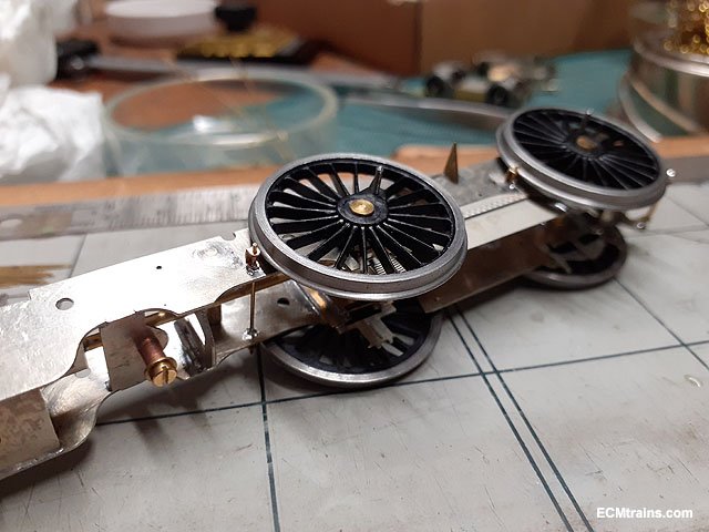
Just about ready to solder them in and I noticed the back bearings were sitting a bit low which held the centre wheels about 1.2mm above track level!
So a slight adjustment of the frames bearing holes was done on the mill.
Adjustments done and the bearings jigged up with the coupling rods, which sat beautifully level for soldering.
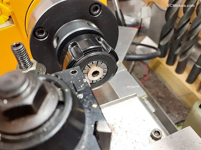
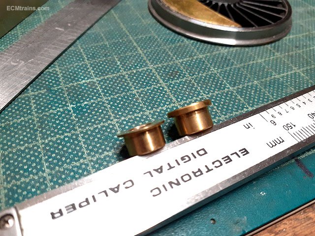
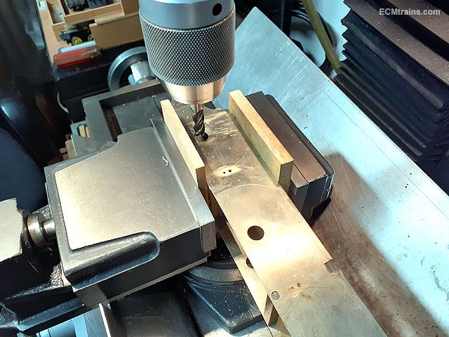
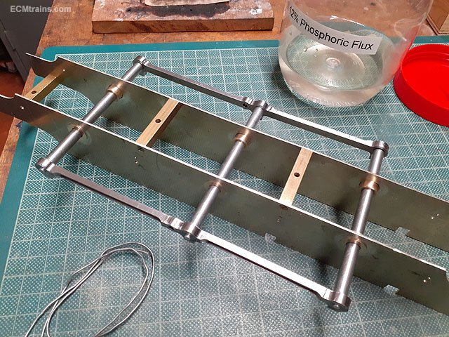
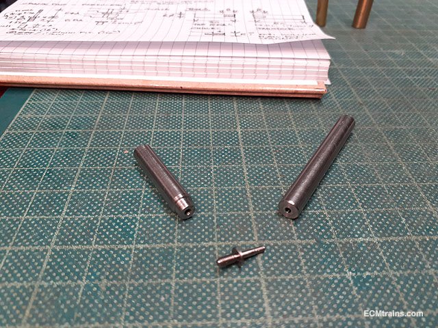
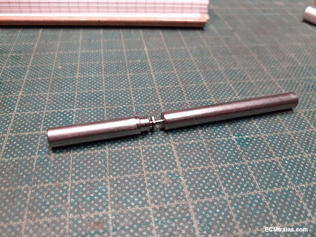
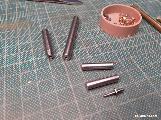
Next was to set up the centre drive wheel crankpins for the coupling and drive rod thickness at around 15mm- this is longer than what is available! Slaters do extended crankpins which will work for the other wheel setups, but the 800 has huge lumps of metal here and I'm kinda sticking to scale! So some extra long crankpins need to be machined and to do this we need two tools- a chuck tool with an 8BA threaded hole and a tailstock tool to support the end of the crankpin 10BA shank which equates to a bar with a 1.65mm hole in it to be held in the tailstock chuck- on the left is the chuck tool and on the right the tailstock tool machined from 6mm MS bar stock.
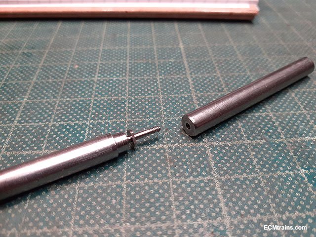
Demo of the Slaters crankpin screwed into the chuck tool.
And now the 10BA shank in the tailstock tool.
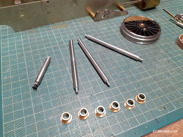
The 6mm bar stock parts cut to length and ready to be machined, thats a Slaters long crankpin below the bits.
Eoin.
-
7
-
1
-
-
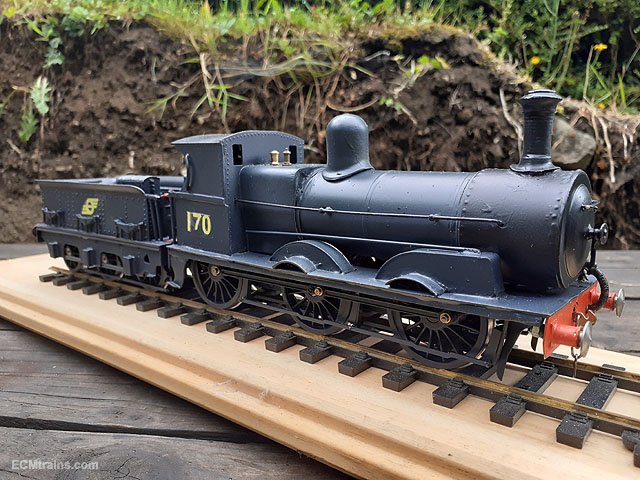
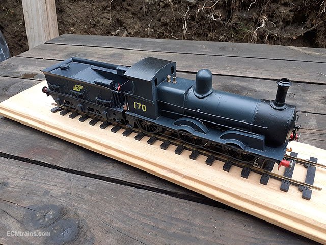
A few photos of the model just before the crew calls to collect it;-
Finished.
Eoin
-
10
-
4
-


GNRi Class V Merlin Gauge OO Build
in ECM Model Trains
Posted
Yes, I have that kind of feeling to.
When looking for photos on line of 85 I found a lot of H&W restoration photos to.....
Eoin