

murrayec
-
Posts
2,681 -
Joined
-
Last visited
-
Days Won
69
Content Type
Profiles
Forums
Resource Library
Events
Gallery
Blogs
Store
Community Map
Posts posted by murrayec
-
-
Hi James,
The Hornby Elite is known as a problematic controller, I would suggest trying the locos on a friends controller of better quality if you can! This would eliminate your controller from the programming/test of the locos and see what happens then.
You should consider upgrading to a better controller- Roco Multimaus is a good starter, Roco Z21 would be next but more expensive, and there is more......
Eoin.
-
 1
1
-
 2
2
-
-
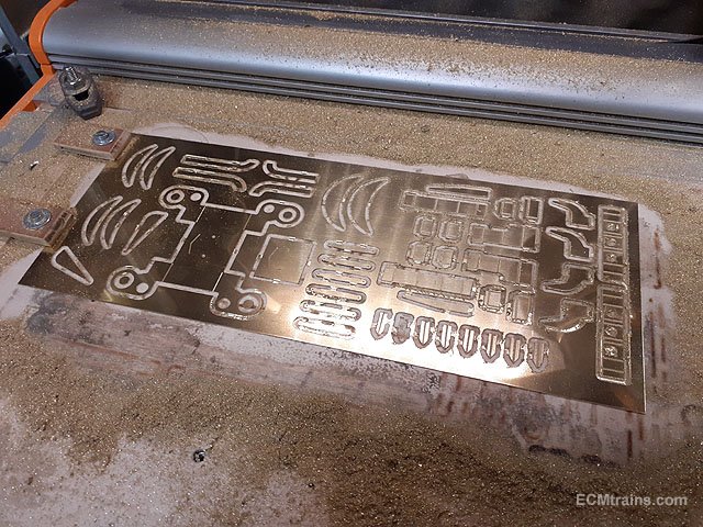
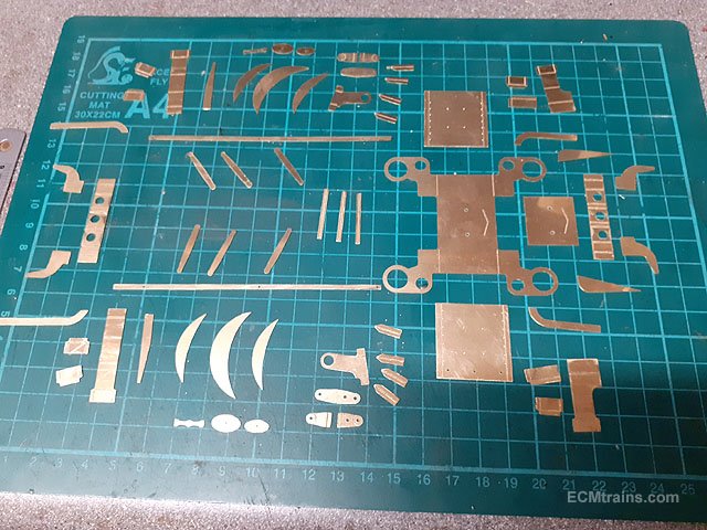
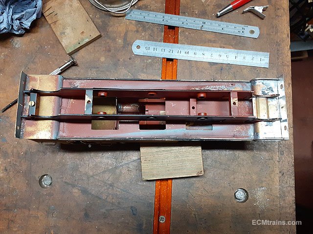
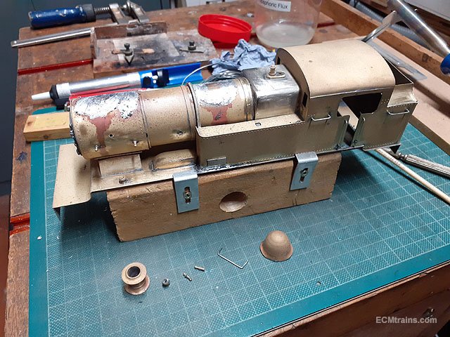
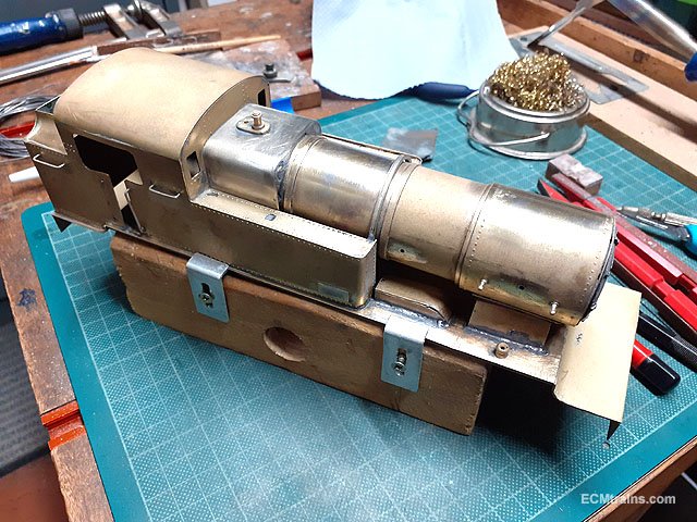
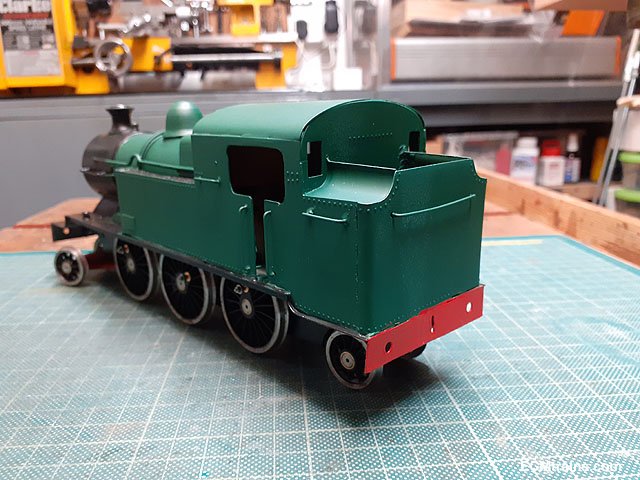
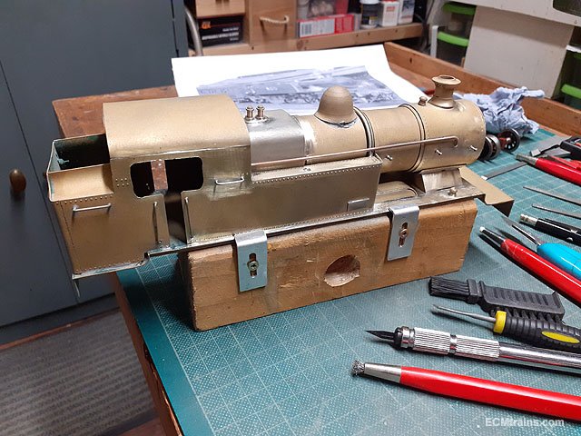
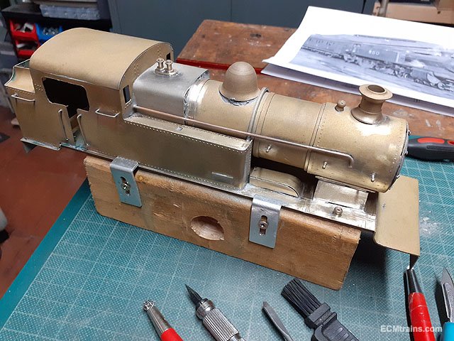
Work on 850 continues;-

Parts cut out on the cnc machine and cleaned up.
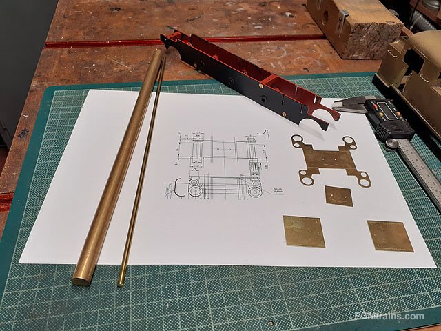
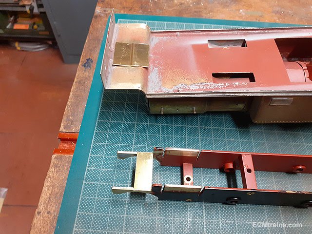
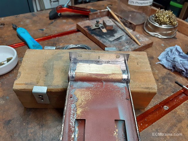
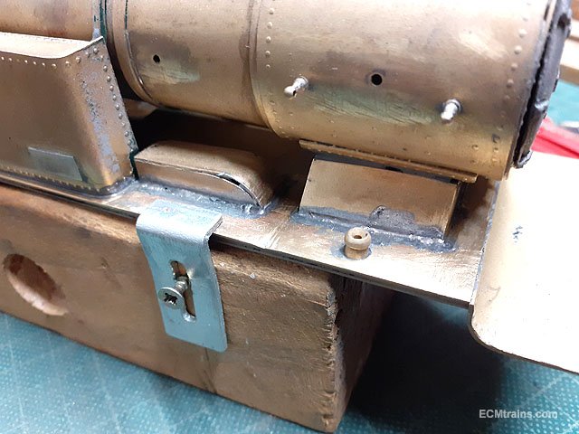
When starting to set up the cylinders I realised that the chassis first needed its fixings to the body so I could work out the space I had to work with- the front of the cylinders are rather close to the front footplate down-turn. Also, the front valance parts need to be in place.
The front of the chassis will be held by a tab soldered to the underside of the footplate with a cross piece across the chassis frames to slide into the tab, the rear will be screw held to the body under the bunker.
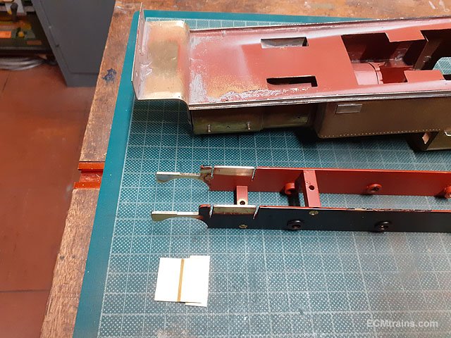
The dodgy front buffer beam was removed.
One can see here, how off line the front footplate is.
A new buffer beam being setup in tin-plate and the footplate has been corrected.
Beam holes drilled and hook slot cut out, now ready to be soldered on.
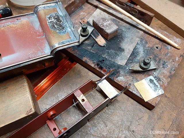
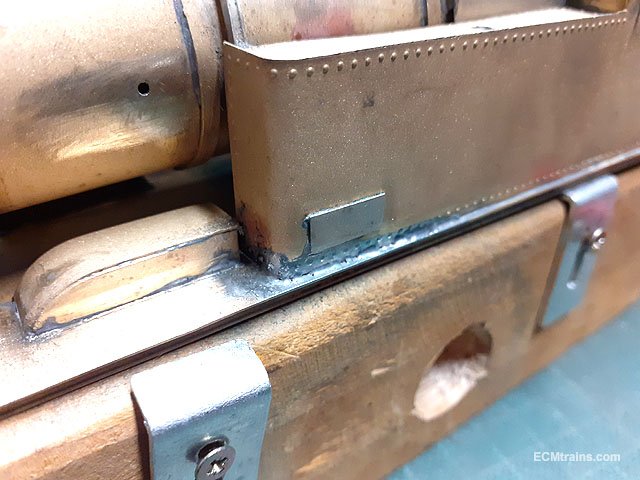
Front valance pieces were made from OO track rail to match that on the body. I did cut brass parts out for this but decided to use the rail instead.
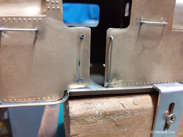
Footplate chassis frame parts are soldered on.
Same with the front valance parts.
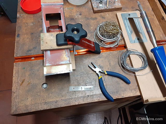
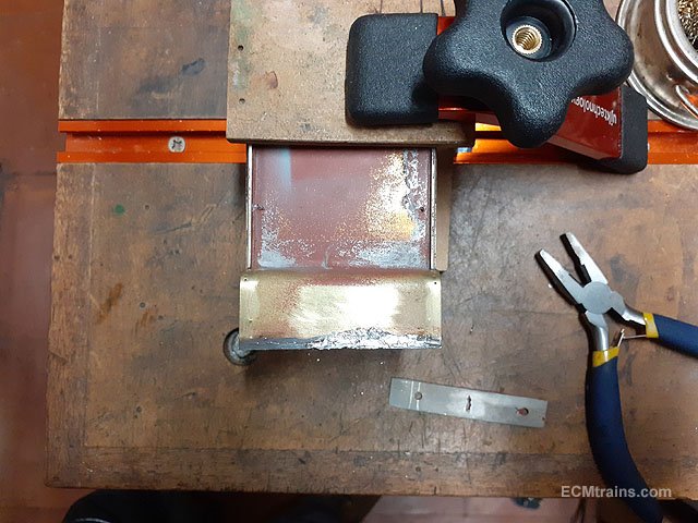
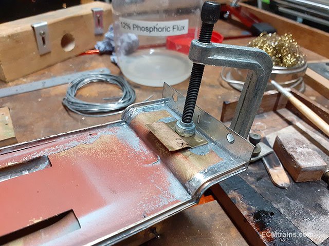
Chassis mounting tab pre-thinned ready to be solder on the underside of the footplate.
Clamping arrangement for soldering.
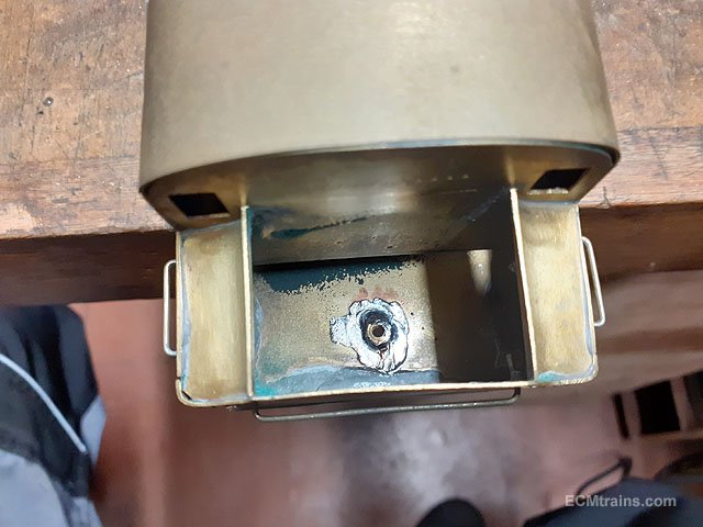
After sorting where the rear screw will be, a hole was drilled in the floor of the bunker for a 6BA nut to be soldered in.
Chassis fitted.
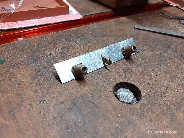
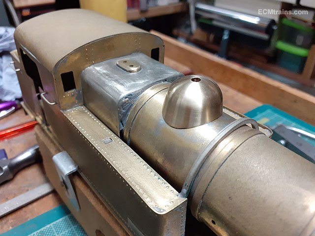
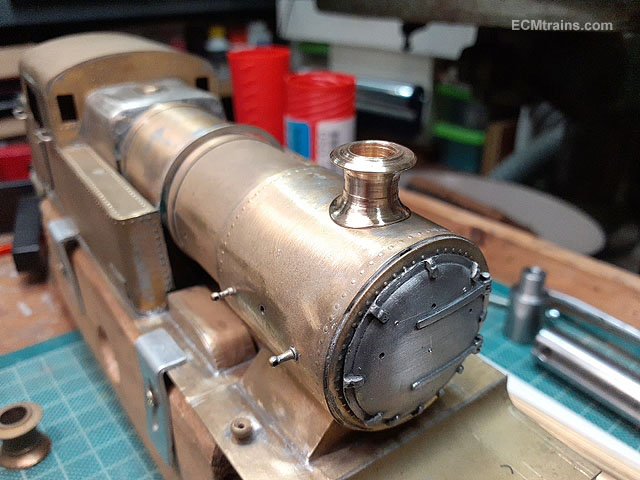
Drilling holes for the boiler fittings- steam dome, snifting valve and chimney.
Done for now.......
Eoin
-
9
-
 3
3
-
-
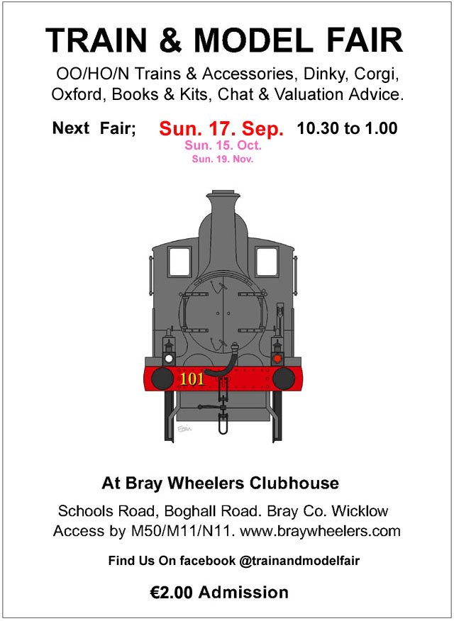
September Fair Date;-
-
1
-
-
The August Fair Date;-
-
4
-
-
@DJ Dangerous Paul Spooner - the man for automata! If he were a railway modeller he would have automated working crew in all his locos!
I have built one automata railway wagon with a man dancing a jig as the wagon is drawn behind a loco! It was based on Spooner ideas. I may show it sometime later!
Eoin
-
2
-
-
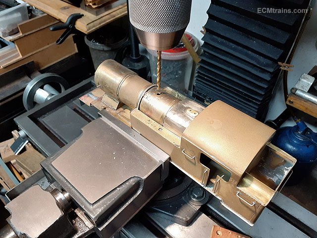
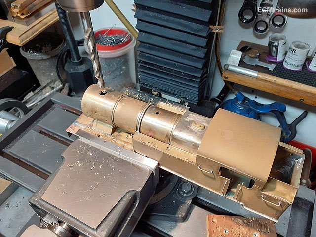
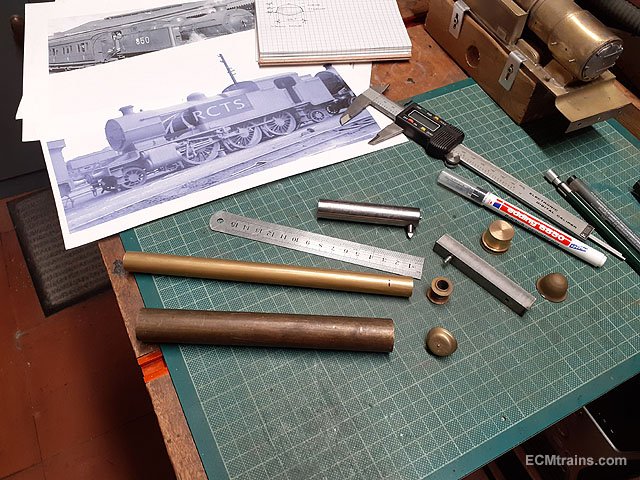
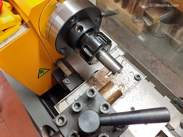
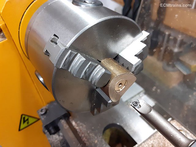
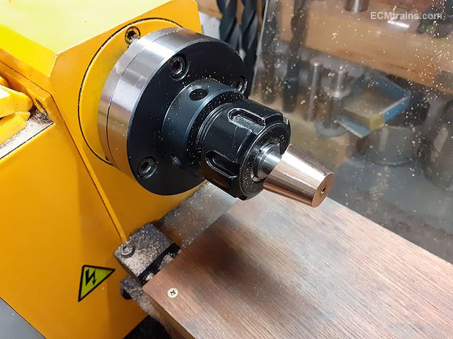
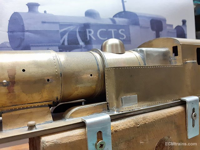
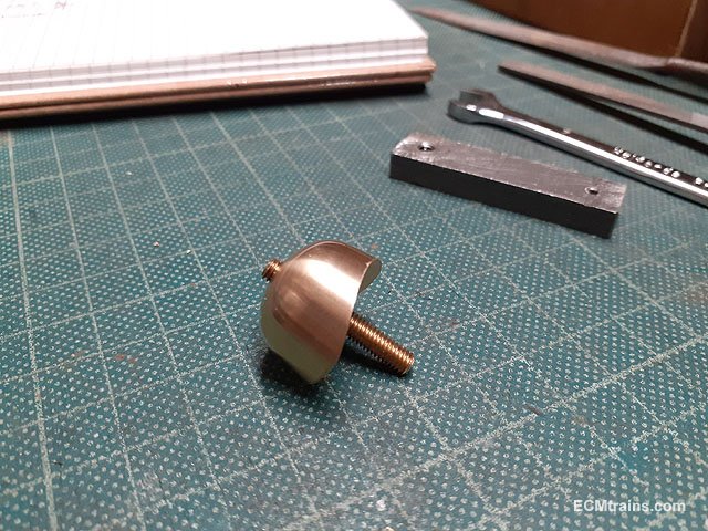
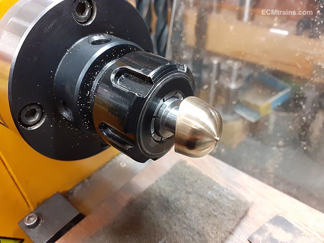
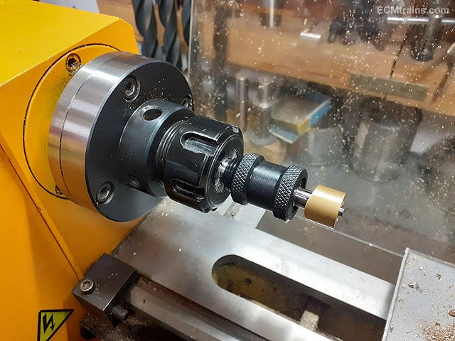
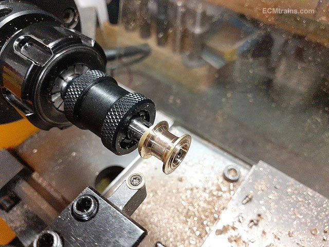
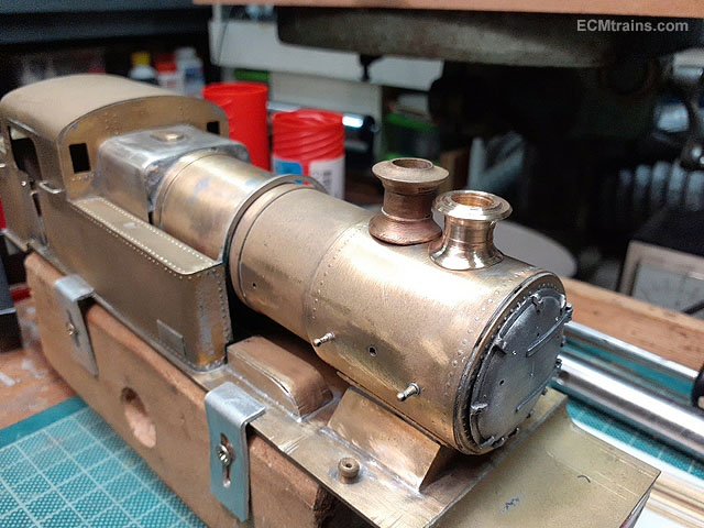
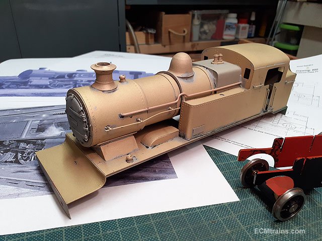
Having a go at the new steam dome;-
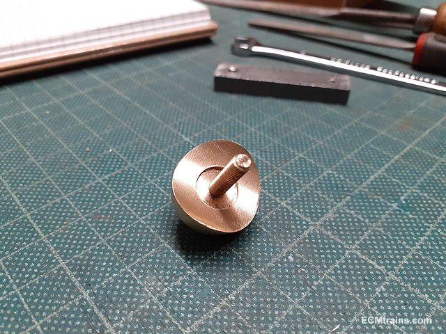
After working out the sizes (I also decided to make a new chimney- slightly smaller then the one removed), two slugs of brass were cut from bar- 22mm dia for the dome and 15mm dia for the chimney.
The dome slug in the chuck just about to be tapped M4 for mounting in the toolpost bar to cut the boiler curve on the base of the dome. The radius is 17.5mm
Now mounted on the toolpost bar, set at 90 deg and ready to fly cut.
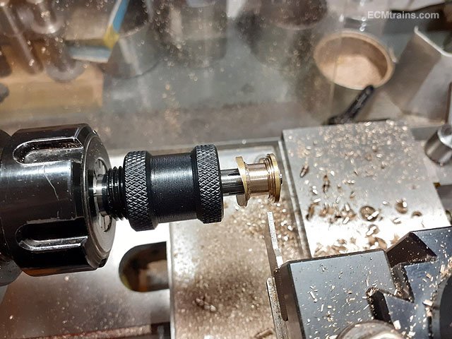
Cut- slightly out of focus! The mounting bar required 3mm packing to get the work-piece centred on the axis of the lathe. The first light cuts show if your on centre, then one packs out until the cut is centred on the tapped hole.
Checking fit.
A recess is bored out of the base for the work to be mounted lock-face on the mandrel.
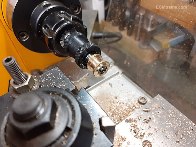
Now the work-piece is mounted on the chuck mandrel.
Ready to cut the side.
I estimated the sides to be at an angle of 10 deg. so the topslide was set over to 10 deg and the cutting was done with the topslide to get the taper.
Taper complete.
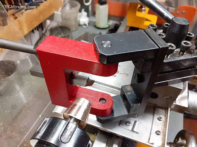
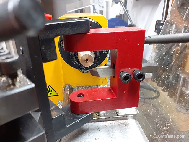
This is the tool setup for cutting the top curve, it's a Ball Turning Tool mounted in the toolpost with the cutting tool set to cut a 19mm radius curve, the lathe is run backwards in this set-up as the tool is cutting on the backface of the work.
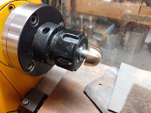
Curve done, cleaned up with files and emery paper.
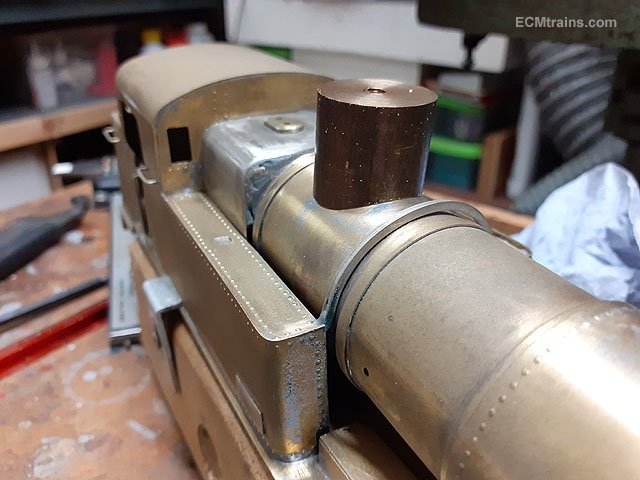
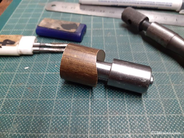
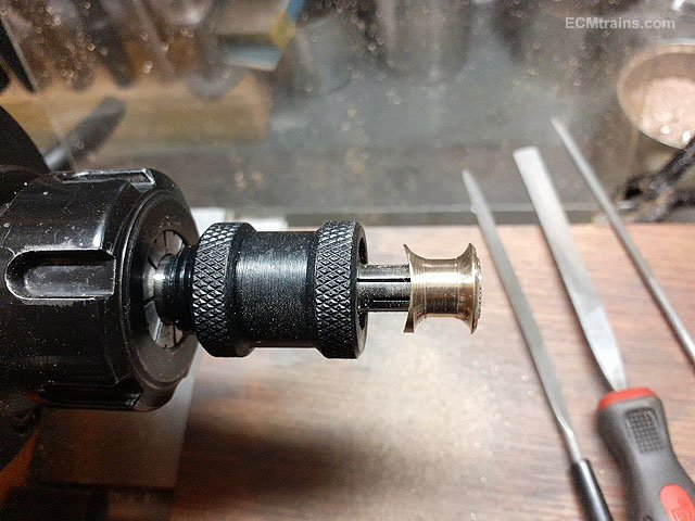
Test fit.
M4 brass screw fitted.
I engraved a bead line around the base of the dome with the point of a calliper/divider.
Then back into the chuck to turn down the M4 screw to imitate a top nut on the dome. The screw is Locktited in first!
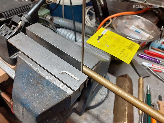
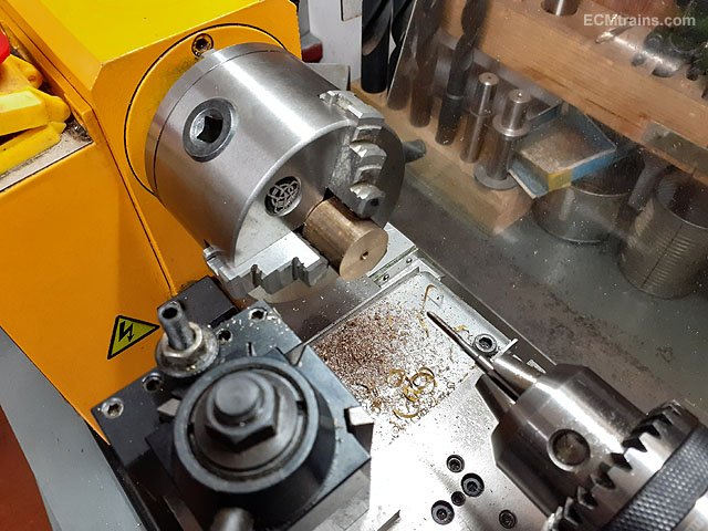
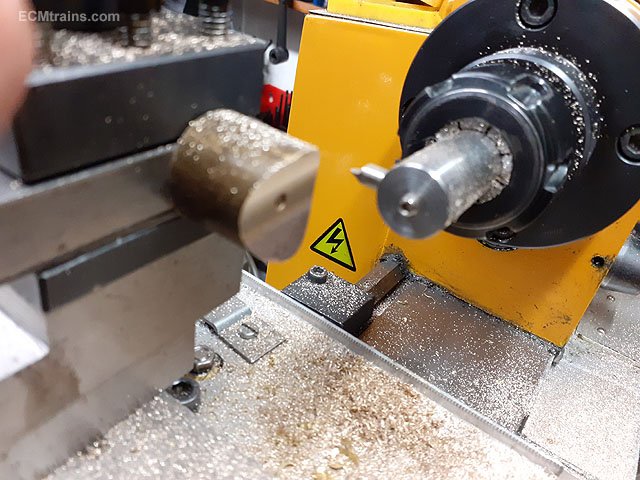
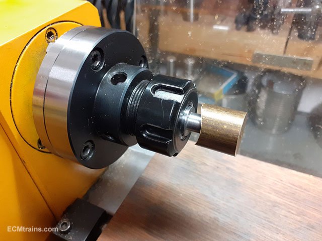
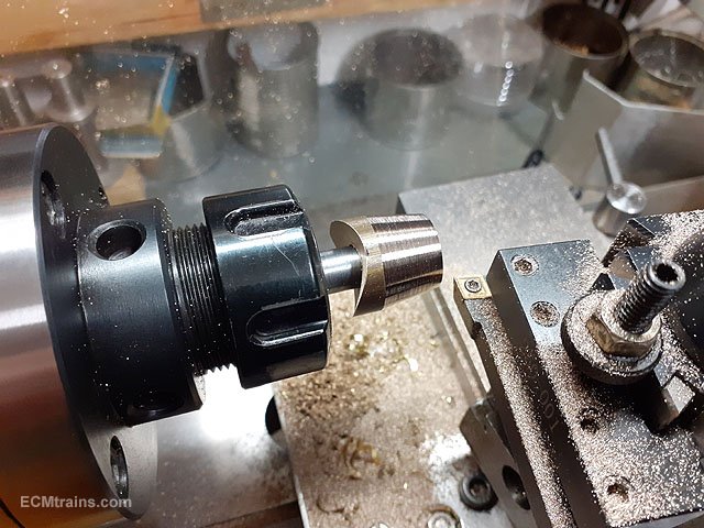
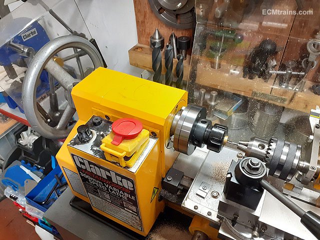
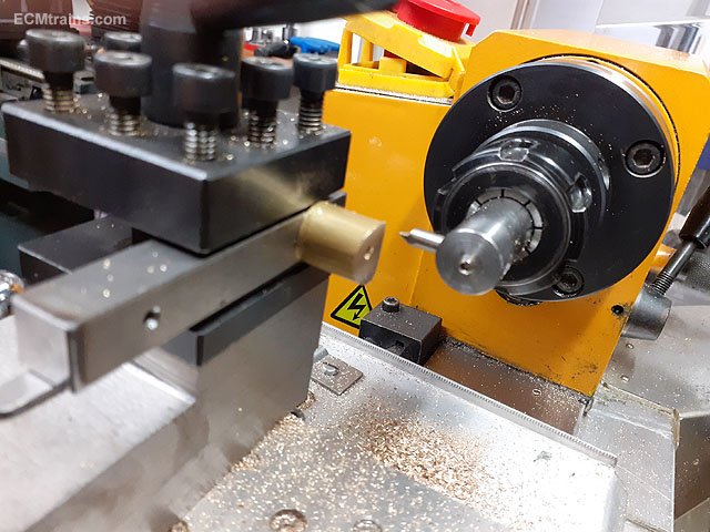
Next the chimney, this is my setup for threading on the lathe, the slug is in the chuck after being drilled through, I disengage the drive motor, mount that handle to the left in the lathe mandrill and rotate the work with the aid of the handle while pushing the tailstock along the lathe bed- tapping the work.
Fly cutting the curve base of the chimney. The radius is 19.5mm.
The work is then drilled through with an 8mm drill. One has to have a hole in a chimney.....
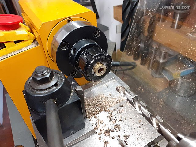
To turn the outside of the chimney the work is mounted on an expanding mandrel, it expands when tightened up and holds the work for light cuts.
Mounted in the chuck, the tail stock can be used here to support the work on the right but it gets in the way in what I'm doing, so light cuts are a must with so much overhang!
Rough cuts with a parting tool.
Finishing cuts with a round tool.
Filling down the sides, top one is done with the bottom yet to be.
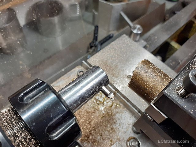
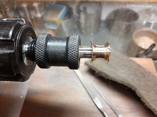
Complete.
Test fit.....
.......and comparison with he one that was removed.
More later
Eoin
-
7
-
7
-
-
The Date For The July Fair;-
July 23, 2023.
-
1
-
-
The date for the June Fair;-
-
4
-
-
Excellent stuff Ken.
Eoin
-
1
-
-
If the wheel sets have pinpoint axles? one could drill out the inside of the bogie frames and install brass pinpoint bearings......
Eoin
-
2
-
 1
1
-
-
Wow, there's a project that got lost in the attic! must do some more work on it.......
I also acquired more bits to build another one or two!
Eoin
-
 1
1
-
-
The May Fair Date;-
-
1
-
1
-
-
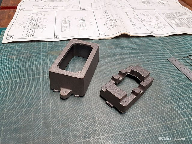
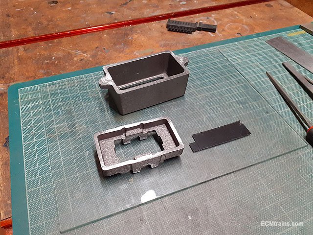
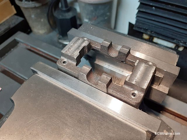
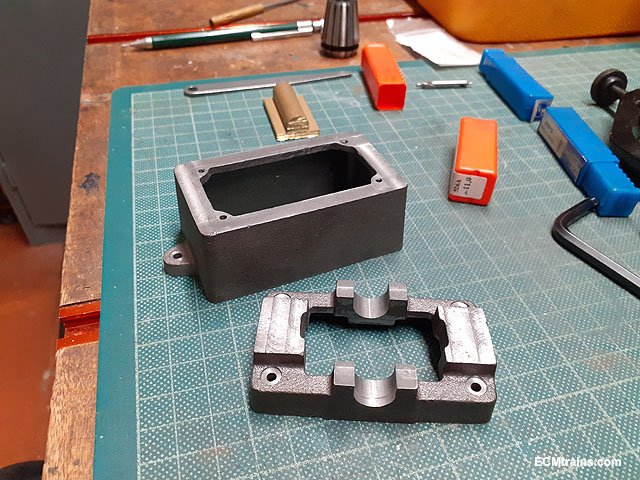
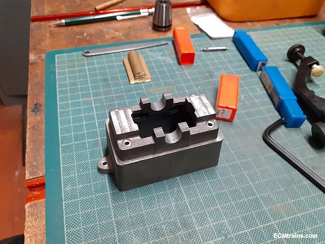
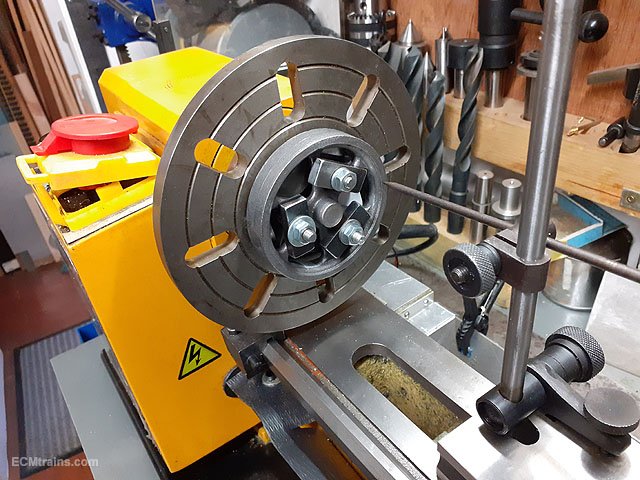
Milling, drilling & tapping the cast iron Boxbed & Soulplate parts for a Stuart 10V steam engine.
The parts from the kit.
The casting gates were cut off and the faces hand filed for mounting in the mill vice.
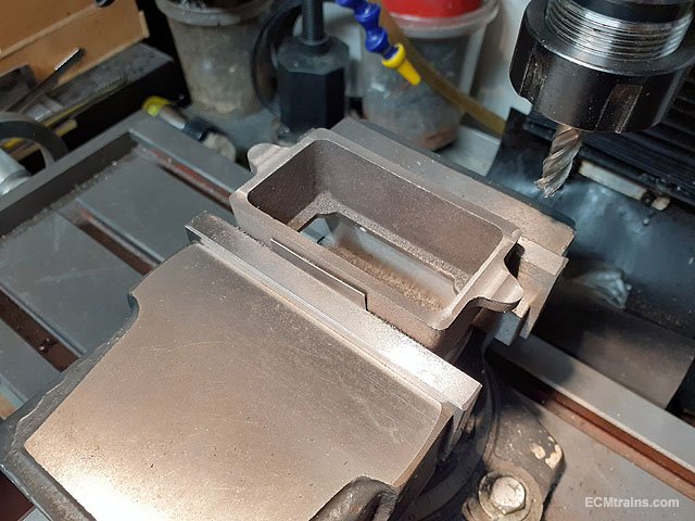
Base of boxbed milled level. Hard cardboard is used between the casting and the vice jaws, this helps to increase the hold on the sandcast surface of the part.
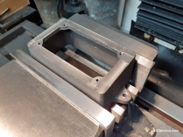
Boxbed turned over with top face milled level, drilled and tapped 7BA to take studs to mount the soleplate. The 2 base fixings are drilled out 3mm clear and the top face of the holes are spot faced 6mm dia to give a land for the mounting screw heads.
Soulplate with bottom and top faces milled, the mounting holes are drilled clear for 7BA studs with a 6mm dia spot face to the holes.
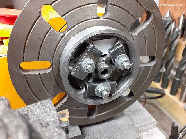
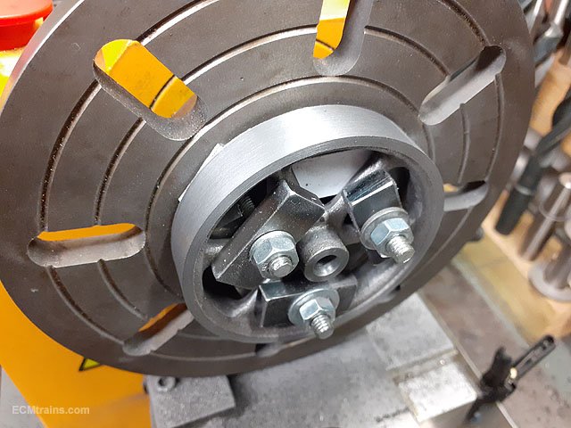
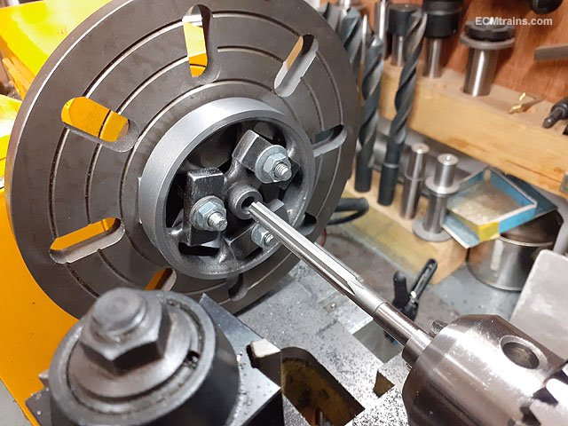
Clocking the main bearing journals to get the casting on centre with the mill spindle. The two journals are going to be milled out to size with an 11mm dia ball end milling tool.
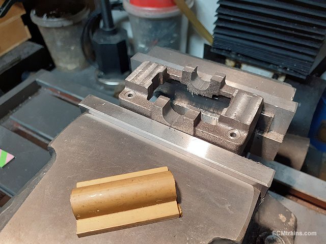
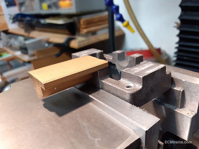
Journals milled, the brass piece is the extruded stock from the kit, for making the two crankshaft bearings that fit into the soulplate journals.
Bearing stock being test fitted in the soulplate journals, it fits- after a few side 'dusting' cuts with the ball end cutter! The cutter is 11mm dia but the bearing extrusion measured 11.1mm (7/16'').
That's these parts finished for now, the soulplate will need more tapped holes for the standard and main bearings, this will be done when the parts are ready so that drilling can be spotted from the parts.
Eoin.
-
1
-
 1
1
-
-
20 minutes ago, Georgeconna said:
Very Education Eoin. Nice little kit too.
Yes, Stuart Models have a lovely range of kits. I also have their beam engine kit which I'll keep for another rainy day!......
https://www.stuartmodels.com/products/set-of-castings/
Eoin.
-
1
-
-
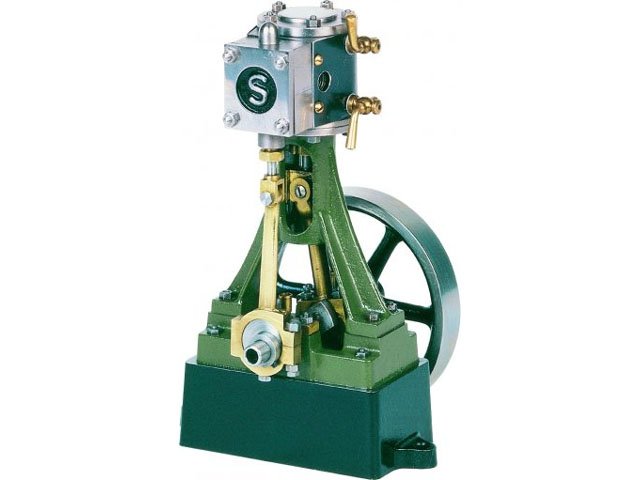
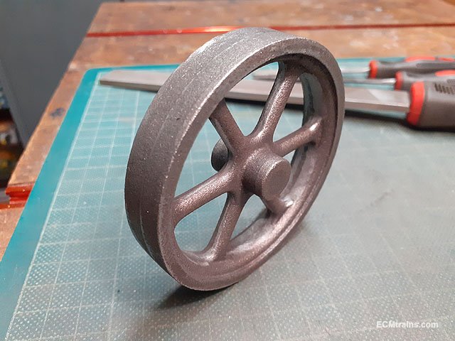
Turning a cast iron flywheel for a Stuart 10V steam engine.
This is a live steam working model.
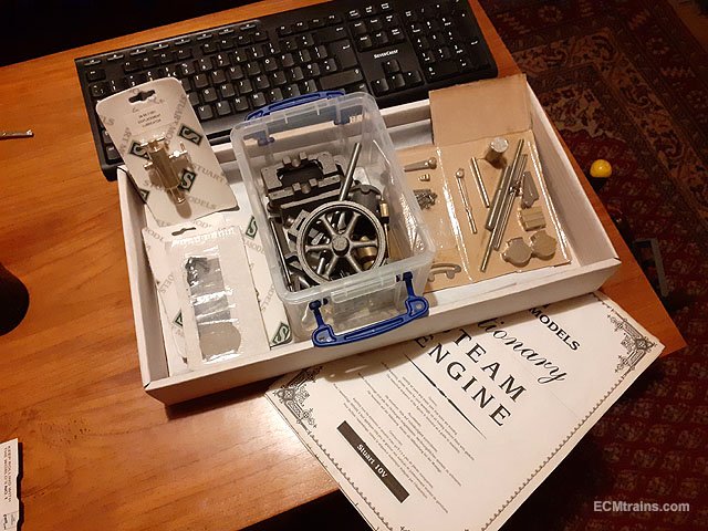
This is the kit of unmachined parts, all the materials are supplied to build the complete engine, drawings come with the kit but no machining instructions. I also got the reverser kit, oil lubricator and a few other bobs! These kits can be purchased ready to be assembled but that takes the fun out of it........
A 64 page booklet can be purchased from Stuart Models or TEE Publishing describing the machining process, it is fairly comprehensive but does miss out on a few things.
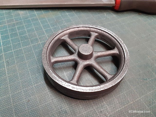
The flywheel;-
The casting spru was cut off on the bandsaw, and all casting flash n bumps were removed with hand files. Stuart Models have an excellent reputation for their metal casting.
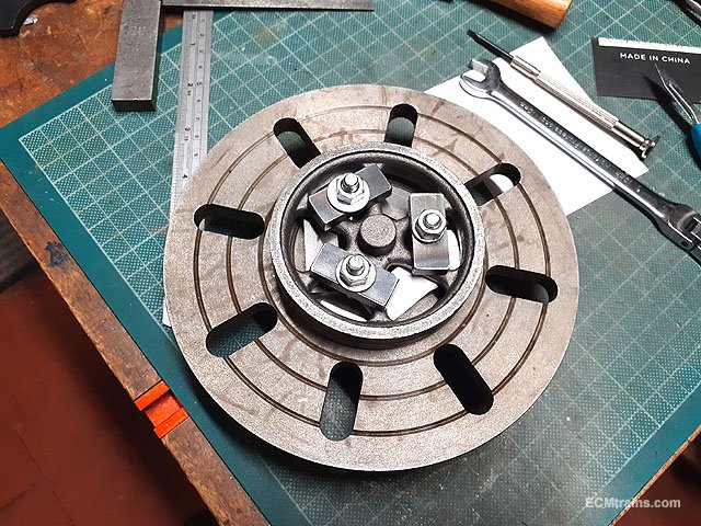
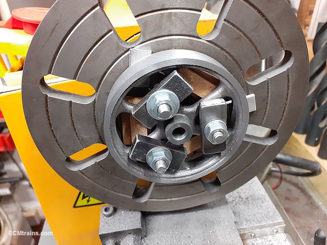
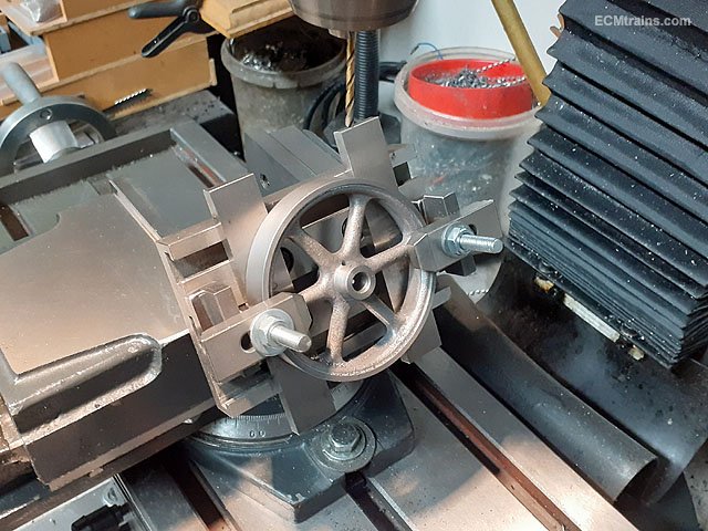
This is the lathe faceplate holding setup, its easier to do this on the bench and then transfer to the lathe. After assessing the position of the flywheel spokes 3 holes were drilled and tapped M6 in the faceplate to take M6 studs and clamping plates. The rim of the flywheel is supported in 3 places off the flywheel by 2mm thick aluminium shims. Packing is installed under the spokes so when the clamp nuts are tightened up one does not break the casting!
This photo shows the 2mm shims which hold the flywheel off the faceplate so that the lathe tool can cut the outer face without bumping into the faceplate. The rim on the flywheel is quite deep, so this allows for the shims to be recessed in from the flywheel outer face, leaving this face free to be machined in one setting.
The faceplate is now mounted on the lathe and I'm using a scribing block to through up the inner edge of the flywheel rim. With the clamping loose the flywheel can be bumped with a plastic hammer to get this edge to run concentric. The hub of the flywheel ran fairly concentric after this was done so I was happy to go with this and tightened up the clamps.
Flywheel outer face, the rim face, and the hub face were machined using a general purpose carbide insert lathe tool. Then a 7mm dia hole was drilled through the hub for reaming out to 9/32'' (7.1mm) The model is in imperial units!
Before reaming, the hole was countersunk.
Reamed 9/32'' to take the crankshaft.
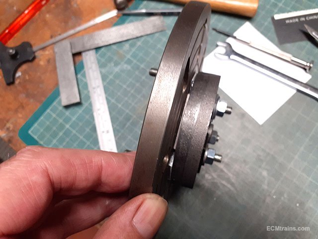
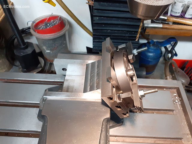
The flywheel was then rotated to machine the other side, the 2mm aluminium shims can now be seen because I'm not machining the outer face in this setting.
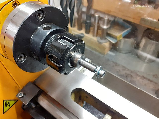
An arbour is now machined up in the collet chuck so that the flywheel can be fitted for machining the hub sides and the inner edge of the flywheel outer rim. The arbour spigot is machined to 9/32'' and just short of the width of the hub so that the M4 cap screw will pull the flywheel up against the arbour shoulder and run concentrically.
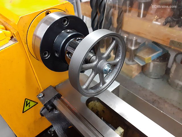
Flywheel on and running concentric.
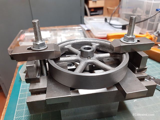
Hub face machined with the general purpose tool and now I'm using a boring tool to cut the inner edge of the rim. All arises were chamfered 45 deg in this setting, the hub arise had to be done with a hand file as the clamping washer was in the way.
The flywheel has a 5BA grub screw to fix it to the crankshaft. This is my setup for drilling and tapping the 5BA hole. The flywheel is clamped on a home spun T-Slot plate mounted at 30 deg in the mill vice.
Another look at this arrangement.
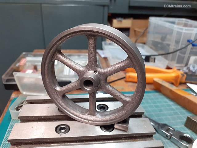
5BA grub screw fitted.
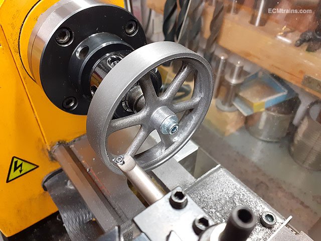
Flywheel complete.
This process can be done using a 3 or 4 jaw chuck, but on the mini lathe with the flywheel at 76mm diameter one is just at the limit of these little chucks so the face plate is a far better option.
I might scoot this over to a thread dedicated to this project....
Eoin.
-
4
-
2
-
1
-
-
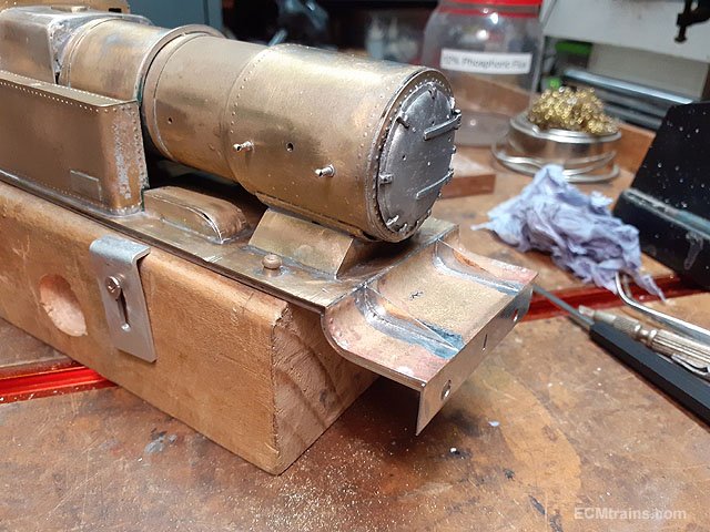
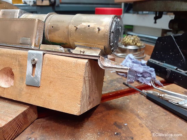
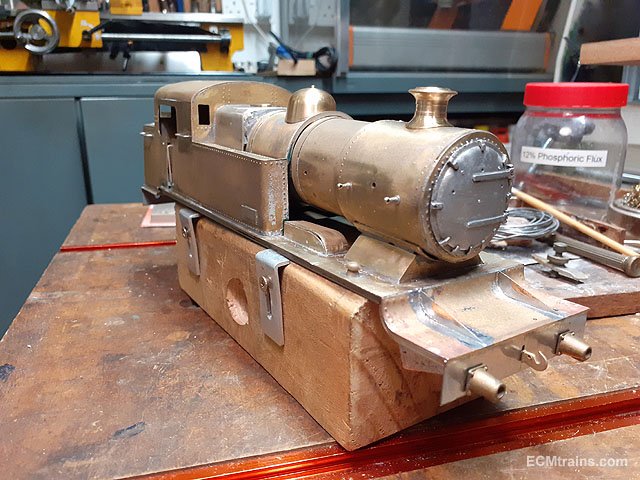
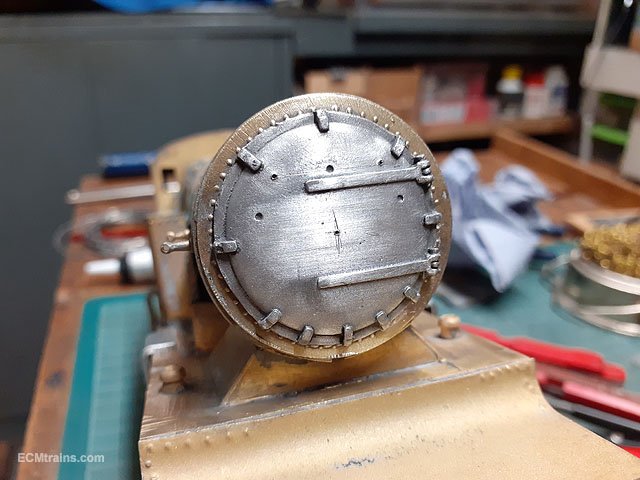
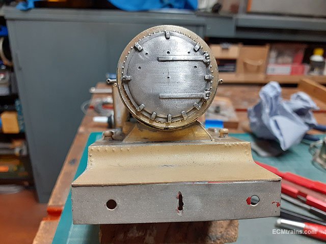
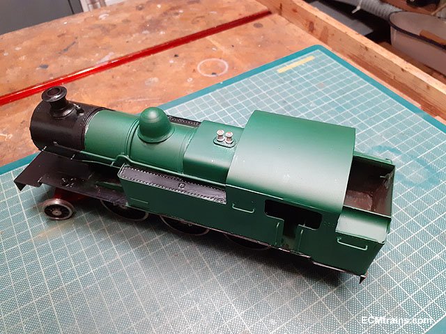
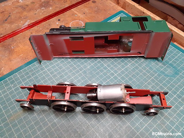
I removed the dome, the chimney, handrail knobs, one short cab handrail, and the snifting valve. While assessing the model I had noticed that the chimney was off centre, I was going to leave it alone but when I had the model hot decided to remove it to correct it.
Again while the model was hot I did a few repairs to some of the soldering, this all had to be done on the outside as there was no access internally.
This is where the short n wonky cab handrail came from, the bottom hole is way off line so a solution is needed to fix this. That hole at footplate level will have to be filled with plastic filler when at the painting stage.
The body being cleaned up after repairs n parts removal.
The smokebox door had a raised number plate on centre, so that was filed off, new holes marked up for a dart handle and upper handrail.
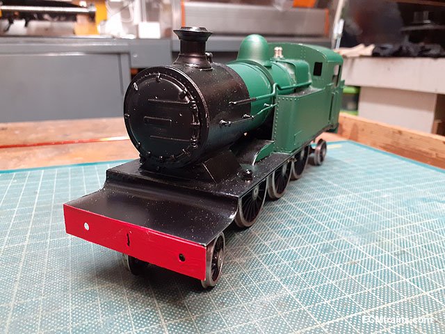
While working on marking out the frames detail to be added to the front footplate I noticed that the right side buffer hole in the beam is off line by 3mm, when the frame pieces are installed this would be very noticeable so I reckon we need a new front buffer beam!
Eoin.
-
9
-
-
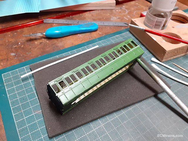
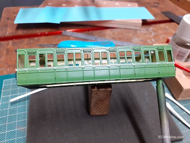
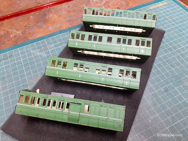
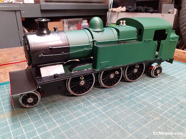
Railtec decal lining & numbers going on;-
Decals complete with a few coats of lacquer applied. I stuck to Railtec's instructions and stayed away from the 'Micro' solutions, but had a difficult time getting the decal lining to sit down over the panel details, used Humbrol Decalfix to assist in the end!
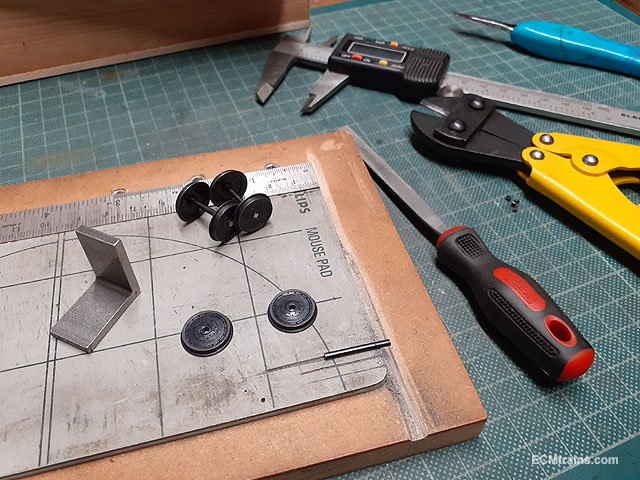
Setting up the wheel axles, by cutting off the pin point ends and filing to size.
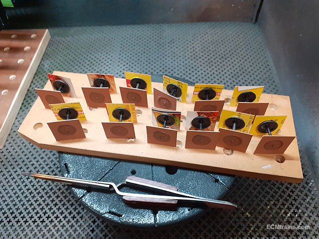
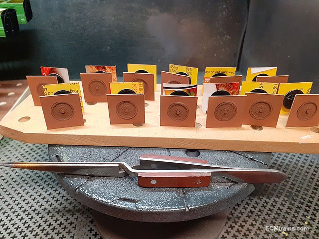
Wheels being weathered before fitting to the chassis, this is the first coat of 'rust' applied. The cardboard masks were cut out on the Cameo Silhouette cutting machine- faster than using masking tape!
Eoin.
-
3
-
-
-
4
-
-
1 hour ago, Galteemore said:
Interesting, Eoin. Stripping the paint off actually reveals that some good work has been done on the body - with some interesting omissions such as not rounding off the Belpaire edges.
Yes, Brendan does great work, but often gives the model to the client before its complete, this is where people contact me to do the completion- if I can!
The Belpaire edges are on the list.
Eoin
-
2
-
-
This model has been on the workbench for some time now, it's a Brendan Kelly/Hamill built model. Now that a number of projects are complete I can dedicate more time to get it finished.....
After having a good look a it and a bit of photo research a plan of action was worked out. The model has been prematurely painted as it's lacking a number of critical parts;- cylinders, valve gear, coupling rods, brake gear, cab opening details, cab roof rain strips, electrical pickup system, footplate frame details and buffers. Although it looks fine with paint on, there are a number of locations on the body that solder could be removed to improve the detail- so it was decided to remove the paint and start there.
Sand blasted
Bits were acquired and the electrical pickup parts are prepared.
Solder clean-up almost complete.
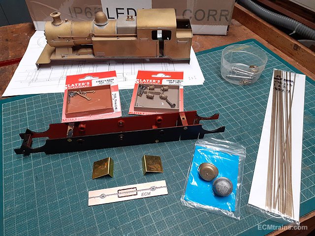
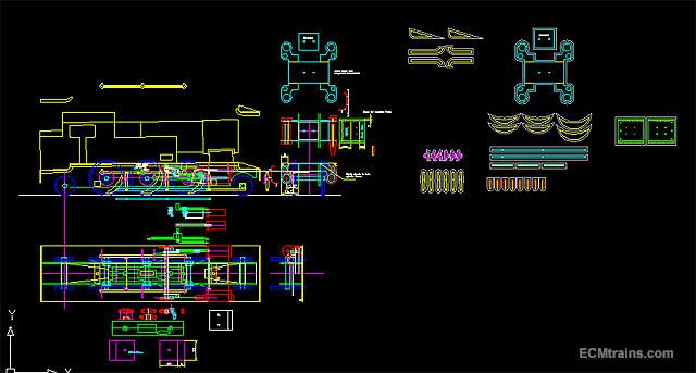
This is a screen capture of the CAD drawing, the drawing was done to work out how to make the cylinders, crosshead, rods, brakes, and a few other bits, the drawings of parts are extracted out to the right, for CNCing from metal sheet.
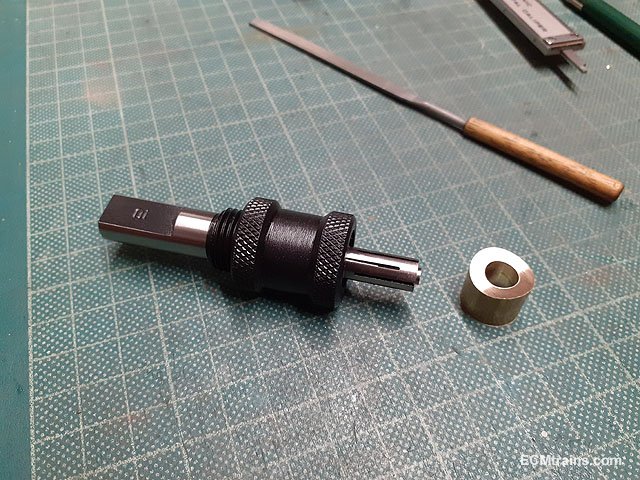
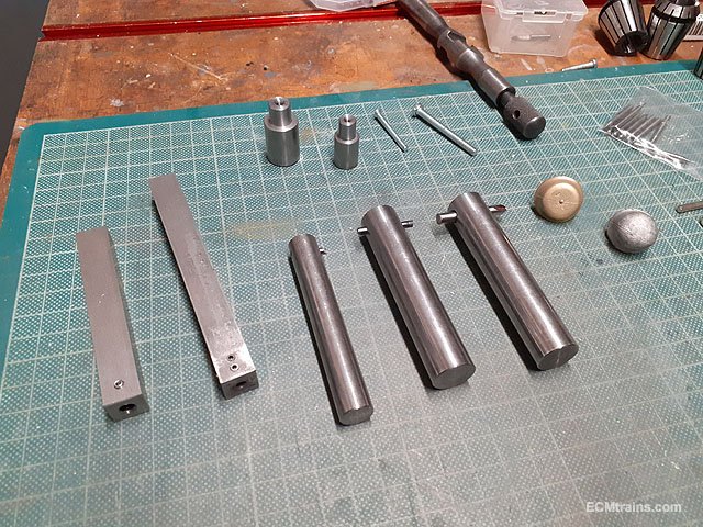
These bits are the tools for making up a new steam dome, there are tools for both Gauge O & OO. The long round bars are the boring bars for turning the base of the dome to fit on the boiler. The short round bars and screws are for mounting the dome in the lathe chuck to form the top curves. The square bars are for holding the carbide tools while sharpening them on the grindstone. There is another square bar yet to be made for holding the work piece in the lathe tool post while the base curve of the dome is being cut.
More later......
Eoin.
-
7
-
2
-
-
April Fair Date;-
-
4
-
1
-
-
The Great Sugar Loaf yesterday;-
Eoin.
-
1
-
-
@FiacraA few photo of the motor mounting would help?
If the motor is mounted directly under the points this could restrict movement as the actuation rod is short and cannot bend for short point movement! So if the motor is mounted with, say a 20mm thick mdf spacer between the motor and point, this would allow the actuating rod to bend a bit and allow the switch to operate correctly??
Eoin.
-
2
-
-
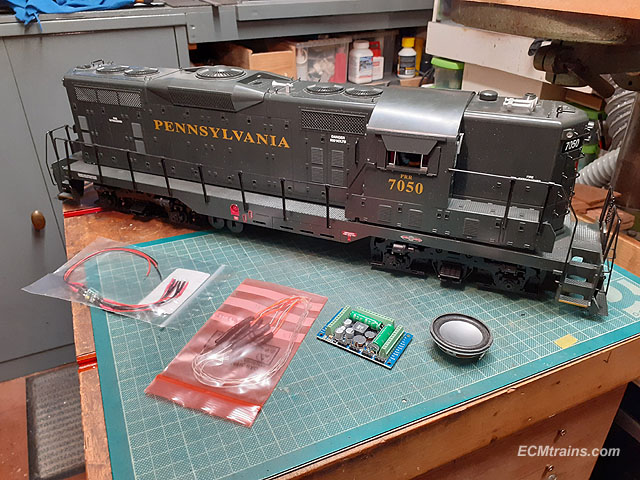
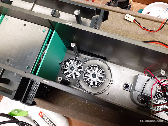
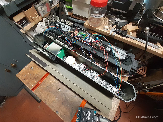
This is a garden railway analogue GP9 loco with lights and 2 smoke generators. The client wanted to upgrade to DCC, so here we go.......
An ESU 5XL DCC sound board was chosen as it has the power for 4 motors, two in each bogie, and a bunch of aux outputs for this upgrade and anything added later. An 8ohm speaker, LED directional lights and LED cab light.
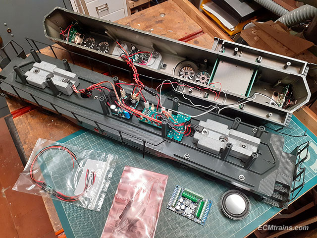
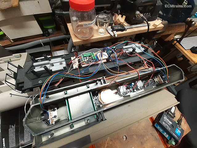
A look at the analogue system, the main board is mounted on the chassis with a number of switches underneath to set the functions, with two analogue smoke generator boards- one mounted beside the main board and the other under the hood.
So after some consideration on how to tackle this I came up with a plan.....
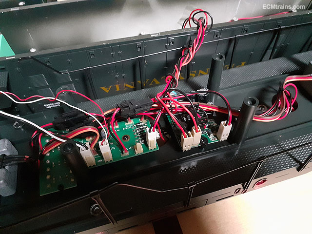
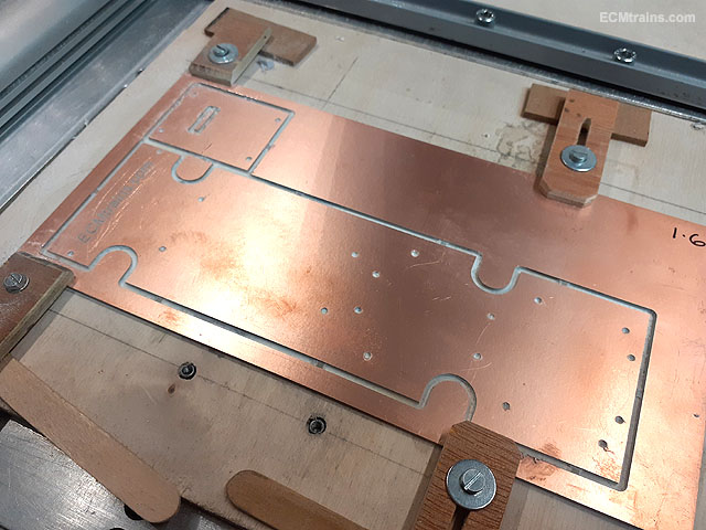
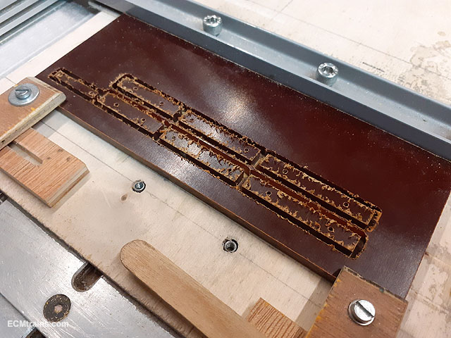
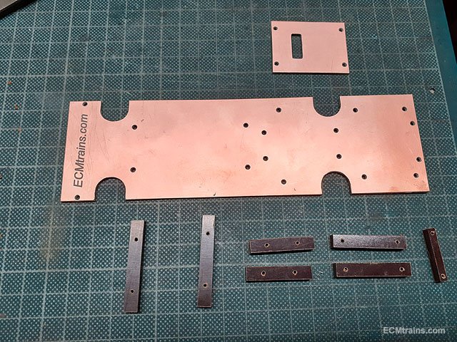
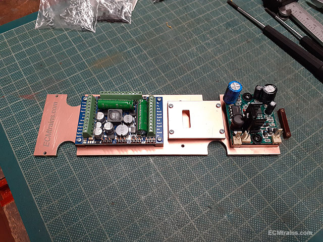
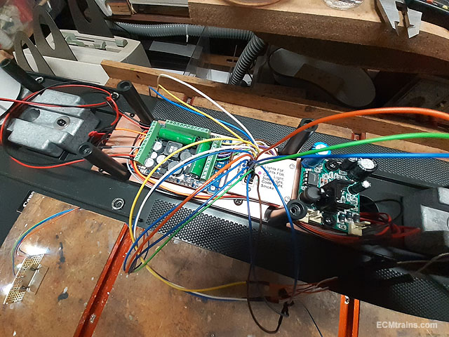
Cutting out a PCB mounting board for the DCC chip and one of the smoke generators, the small board is for mounting a wiring socket.
Riser blocks being cut from 10mm Tufnol sheet for mounting the PCB board to the chassis and risers for mounting the new control boards.
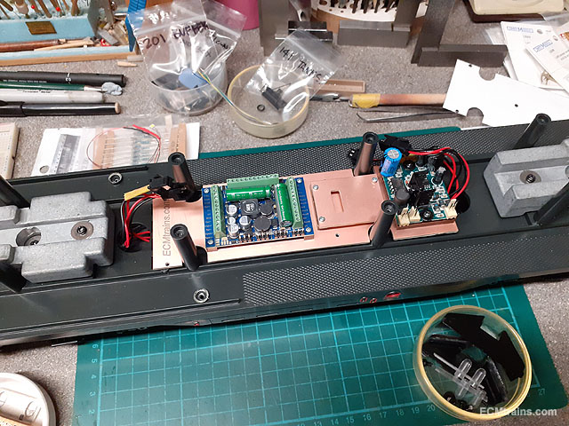
Boards mounted.
And the lot screwed onto the chassis, I used the old mounting lugs on the chassis to screw it down.
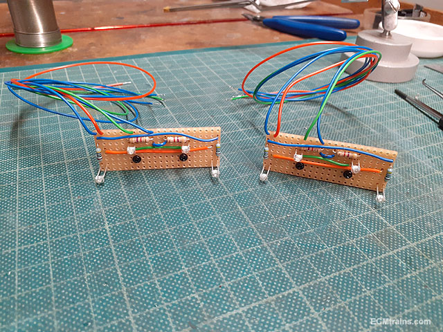
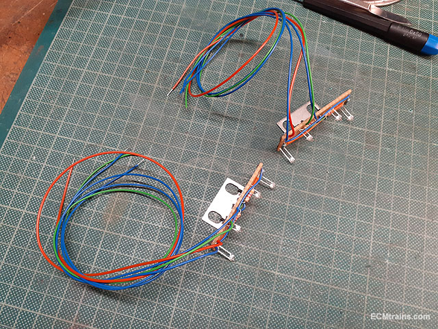
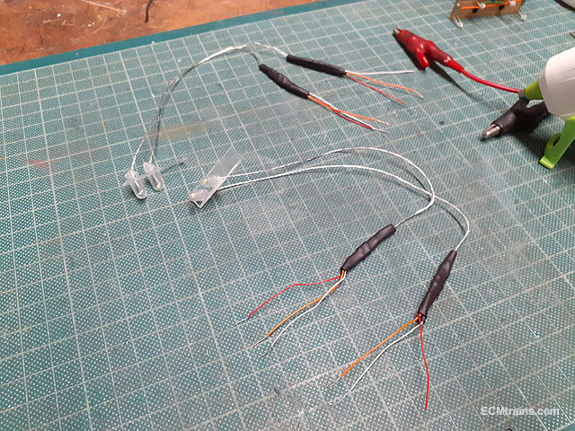
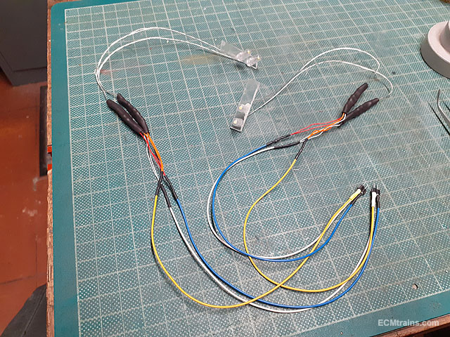
Replacement LED code and side light boards.
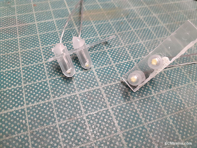
Directional LED head lights being setup.
The LEDs are hot glued into the original front light housings.
A LED cab light was also installed but no photos as to how that was done!
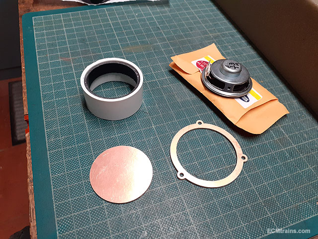
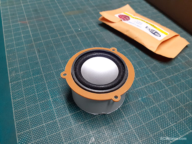
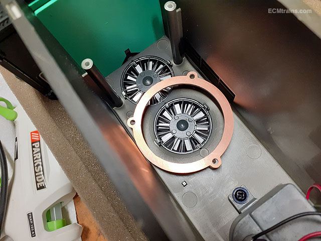
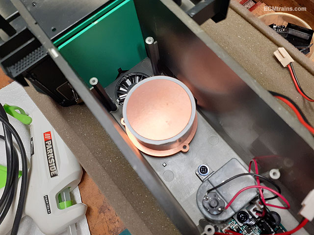
The speaker enclosure being setup, made from some PVC waste pipe and PCB parts CNC cut to mount and close the back after the speaker is installed. when the speaker is wired up the whole will be epoxied together.
The enclosure will be screw mounted onto the 3 lugs around the fan.
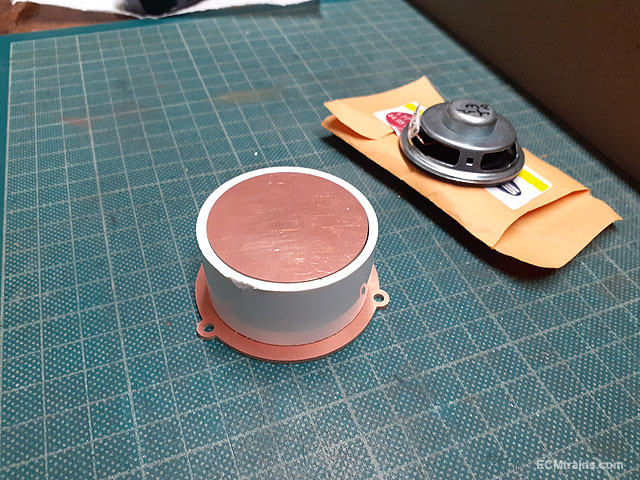
To make this part a paper impression was taken from the screw lugs on the fan, this was scanned into cad, a drawing setup and then the part was cut out on the cnc machine.
It fitted!!
The wiring socket was then made up (sorry no photos) from mini connector soldered onto a PCB board which was screw mounted under the board featured above, a cad drawing print was stuck onto the top to indicate which connection was for what. The bogies, lights, smoke generators and cab light were all wired up and in this photo its all under test and being programmed.
The system complete and the hood about to be bolted down and then off for a test run on it's home layout.
The only problems encountered with the DCC chip, was with the analogue smoke generator boards, eventually the boards were take out of the loop and the generators were connected straight to the chip and controlled from there.
Unfortunately I lost the video of it running and making it's sounds, when the memory chip on the phone bit the dust. Next time when on a visit I will take some video of it.........
Eoin.
-
5
-
3
-


Ligean Brewery
in Irish Model Layouts
Posted
Excellent work n design Ken.
Eoin.