

murrayec
-
Posts
2,677 -
Joined
-
Last visited
-
Days Won
69
Content Type
Profiles
Forums
Resource Library
Events
Gallery
Blogs
Store
Community Map
Posts posted by murrayec
-
-

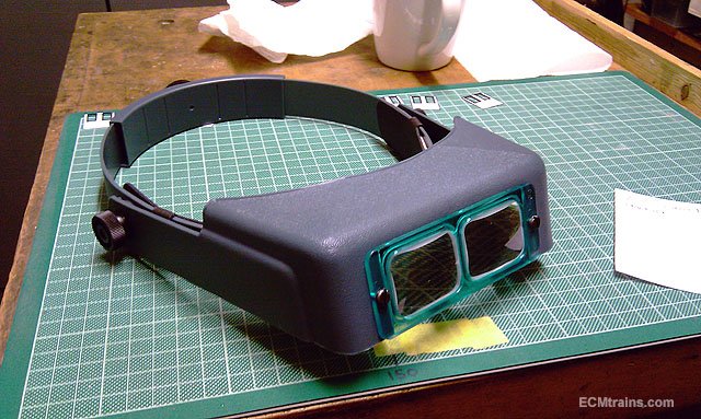
You need a set of these......
Eoin
-
 4
4
-
 1
1
-
-
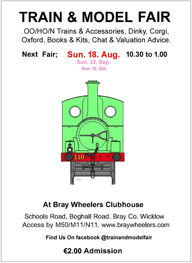
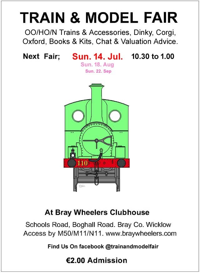
The August Fair Date;-
-
1
-
-
17 minutes ago, Niles said:
The sound is iconic, any videos?
Unfortunately I lost the majority of the files on this project, back in 2021 my computer died and I could only restore a few files! the ones shown above were restored from this forum.
I will be setting up a sound one for myself and will show a video then, or if I meet the client of the above one I'll get some video.
15 minutes ago, LNERW1 said:Not to be nitpicky but isn’t that a 181? As opposed to a 141. Sorry to be a bit pedantic.
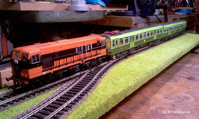
Again those photos above are all I could restore, the loco was renumbered to '143' which was the running number of the actual 141 used.
Eoin.
-
2
-
 1
1
-
-
-
1 hour ago, Broithe said:
There are hooks on the ones that Lidl should have shortly - it will be interesting to see if they are the same height...
https://www.lidl.ie/p/folding-saw-horse/p10029198
They don't seen to have the handy notches, though.
I saw! that was coming, though I think I will stick with what I have.
It's a year (wow!) since I posted on this project! The shed is fully insulated and waiting to be sheathed out inside, I'm going to use the timber I originally bought to build the shed to do this.
Other projects have taken up my time! but should get it done soon......
Eoin
-
2
-
-
Wizard Models Ltd do brass rivet strips and other stuff for wagons;-
https://www.wizardmodels.ltd/shop/wagons/mt163/
Eoin
OOPS! just saw Roberts post!!!
-
1
-
1
-
-
To tag a username- type an '@' and then the user name, a menu will pop up while typing, offering usernames, you can select from that also.
Eoin
-
1
-
1
-
-
July Fair Date;-
-
2
-
-
I like the weathering on the second last image!
Eoin
-
2
-
-
I use a OptiVISOR head magnifier, they have ground glass elements, far more superior than the plastic ones. Though, they do come at a higher cost.
Eoin
-
2
-
-
9 minutes ago, Georgeconna said:
''More I see the silver the better it gets as a livery, I can see why they chose to paint them like that in the 1st place, Sparkles for a moment....''
I assumed they were galvanized?
Eoin
-
Hope these help
Eoin
-
3
-
1
-
-
Very sad, rest in peace
-
Very sad news, a great modelling friend and yes a perfectionist, I will miss him to.
Eoin
-
3
-
-
The June Fair Date;-
-
1
-
-
Check out John Mayne for Tin Van kits, not sure if he still has some left, these would be an ideal starting point and a very nice kit....
Eoin
-
2
-
1
-
1
-
-
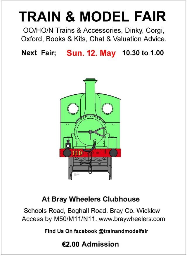
May's Fair Date:-
-
2
-
-
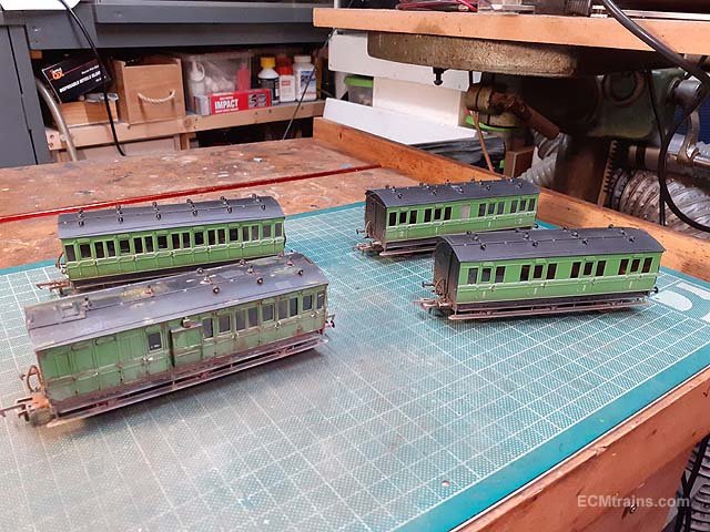
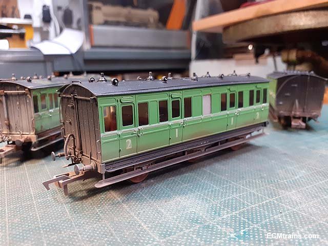
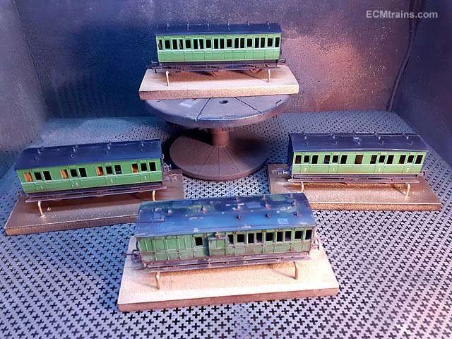
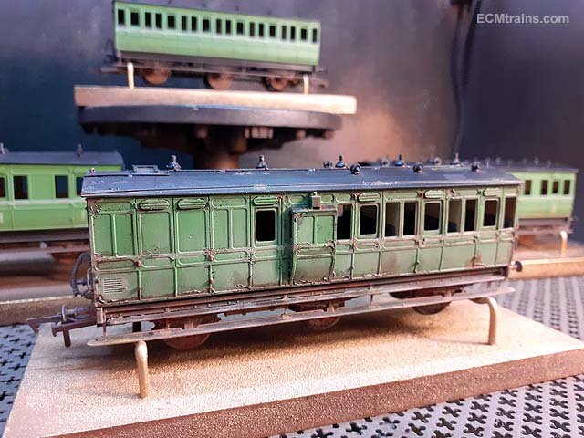
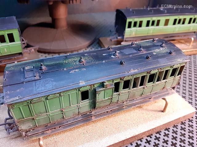
These coaches are now complete;-
Brake 3rd.
All 1st.
All 3rd.
1st & 2nd Compo - Lav.
The End.
Eoin.
-
4
-
1
-
 3
3
-
-
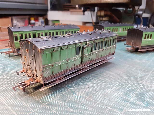
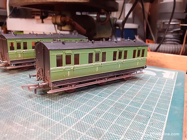
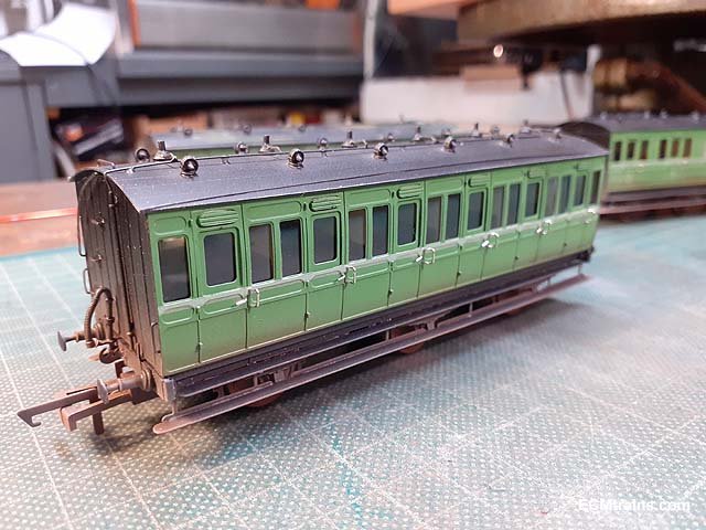
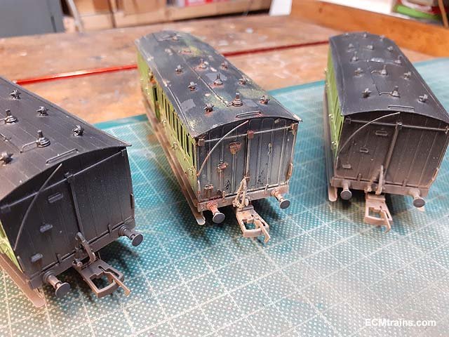
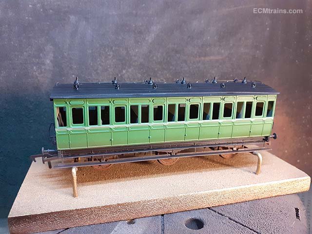
Weathered and lacquered over the last couple of days;-
This build has taken so long that moss & lichen have taken to the roof of the brake van!!
Door handles and glazing next
Eoin.
-
6
-
2
-
 2
2
-
-
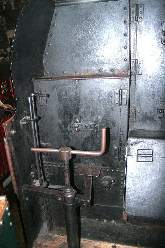
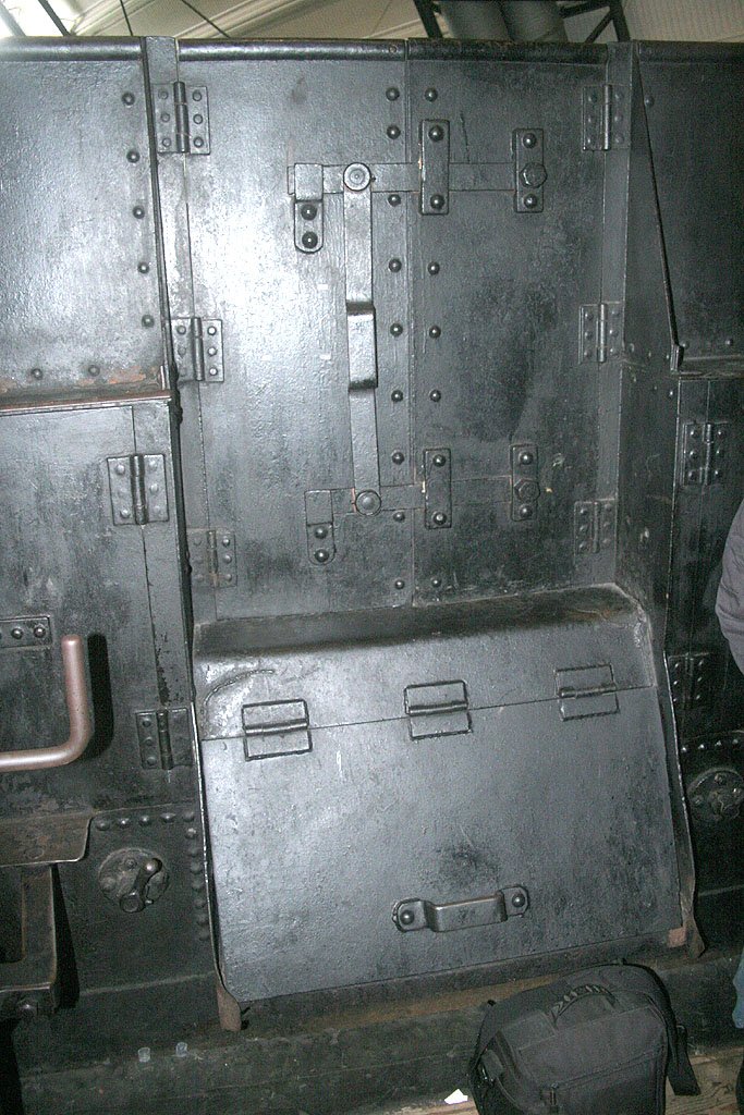
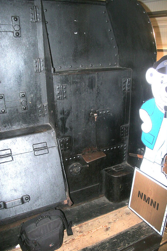
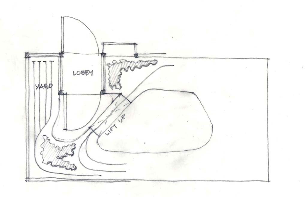
A Lobby;-
Eoin
-
5
-
-
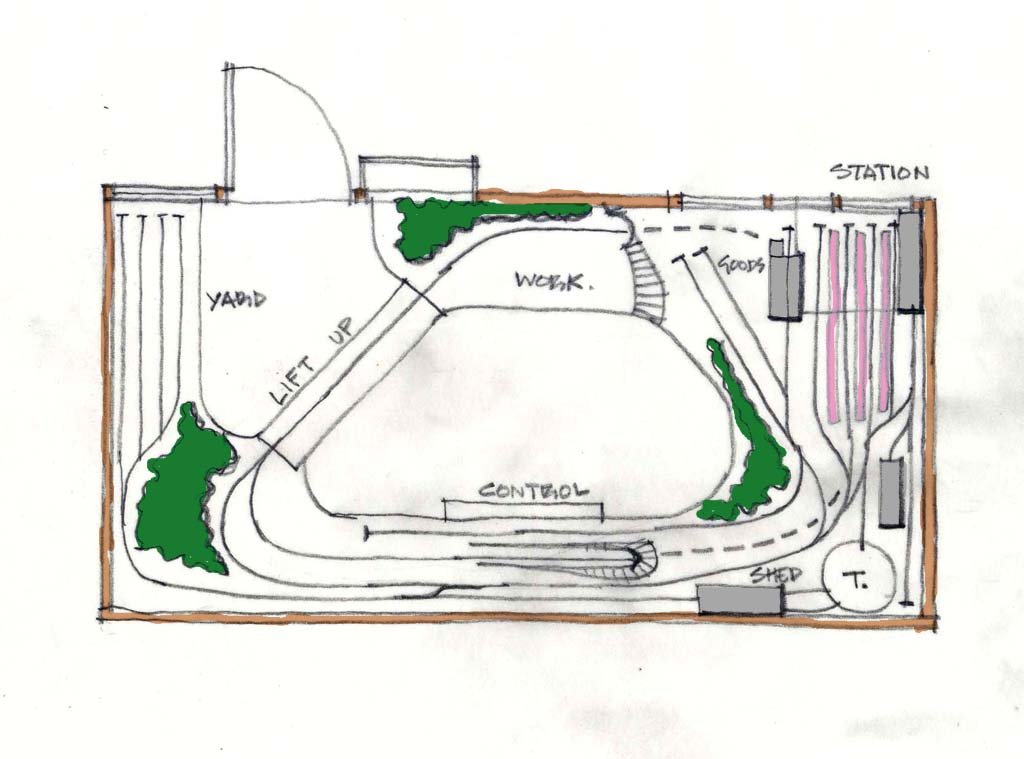
Here is one to kick off the discussion;-
Taken from Mr CJ Freezer's 'Track Plans' Plan No. 1 for a small bedroom!
I have elongated it to suit your dimensions and ignored your lobby, I reckon railway layout space is more important than a lobby.
This plan allows for a train to run on a loop, which runs under the station, so then one can play end to end between the fiddle yard, the goods, the engine shed, and the station at the same time. The trains would have to reverse into the station and would be short!
Eoin
-
6
-
1
-
-
-
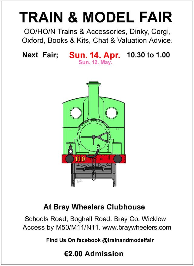
April's Fair Date;-
-
2
-
-
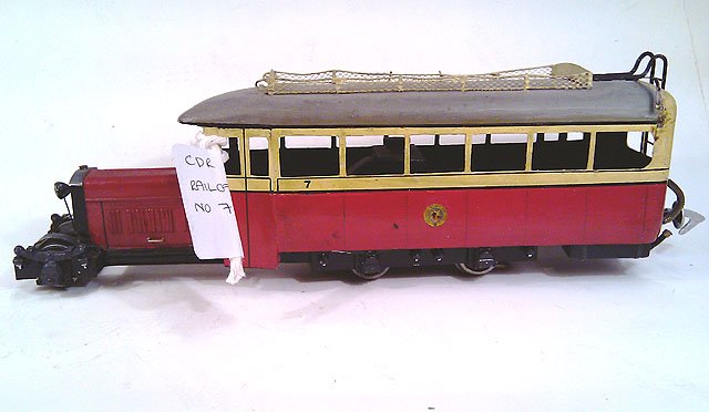
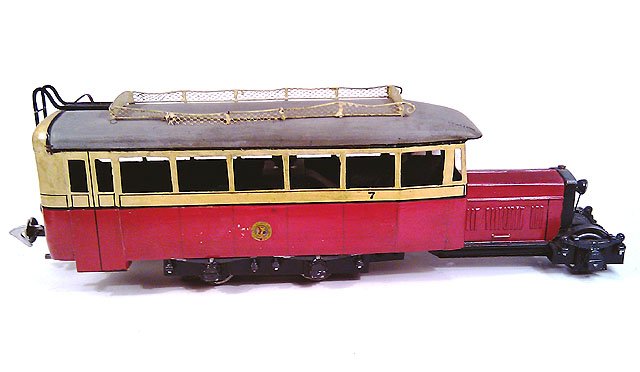
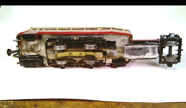
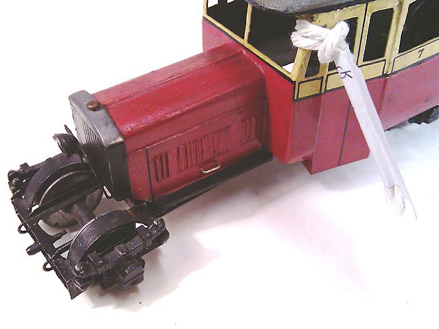
Here are a few photos of Fry's No.7
Eoin.
-
7
-
1
-


trix - hornby compatibility
in Continental European Modelling
Posted
Hi @George,
That Hornby is not a reliable controller, I would recommend you go for a upgrade if you can.
If the SJ 1200 is DCC fitted and set to run 'Analogue', it will run with that controller. If not set to run analogue or cannot be set- no chance on that controller.
If it is DCC fitted, the way to control the models digital functions is with a DCC controller, so if upgrading the Hornby R8250 go for a DCC controller.. Roco Z21 or Multimaus, etc.....
Eoin