Horsetan
-
Posts
2,635 -
Joined
-
Last visited
-
Days Won
4
Content Type
Profiles
Forums
Events
Gallery
Blogs
Everything posted by Horsetan
-
TMD/SSM MGWR "W" / GSR J26 / CIE "551" 0-6-0T
Horsetan replied to Horsetan's topic in Photos of Models
Imitation, they say, is the sincerest form of flattery... -
TMD/SSM MGWR "W" / GSR J26 / CIE "551" 0-6-0T
Horsetan replied to Horsetan's topic in Photos of Models
The line drawing in JHB's Achill Line book is also of 110 "Bat" -
TMD/SSM MGWR "W" / GSR J26 / CIE "551" 0-6-0T
Horsetan replied to Horsetan's topic in Photos of Models
Can't do lining. -
Interesting, because my new thread was started on a PC....
-
Does anyone know why, when I type out a title for a new thread, only the first letter comes out as a capital, whilst everything else remains stubbornly lower-case?
-
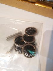
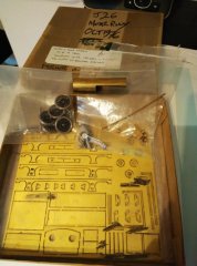
The nature of loco building these days is that people take on additional projects before finishing the ones they've already got. I'm no exception. Whilst working out various schemes for the "S" class inside motion, which is proving more difficult to render accurately than I had first thought, another Irish kit popped up on eBay. This was the old TMD kit for the MGWR "E" 0-6-0T in original form and, joy of joys, it had a full set of Sharman P4-profile driving wheels (long unavailable after Phoenix Paints bought up and then effectively killed the range) plus trim-it-yourself axles for 21mm gauge, and a full set of spacers for 21mm gauge. Initially offered at £50, nobody wanted it and it promptly reappeared at £42. An entire week went by, and still nobody wanted it. About 10 seconds before it went begging for the second time, I took the bait and it was knocked down to me. This is what turned up: Fortunately it came with a full set of the original instructions, which referred to a (missing) nickel silver chassis - superseding the old etched brass chassis. At this point, Des at SSM (who now produces the kit, pretty much unchanged) stepped in and kindly agreed to supply the missing etch plus some extra boiler fittings from another kit for not a lot of Euros, so payment was made and hopefully these are now in the post and coming this way. For anyone contemplating 21mm gauge Irish steam, you can't get much simpler than a nice 0-6-0T to start you off. You will learn loads about suspension systems and weighting. The question for me is what to do with the thing. Those who know me in P4 will be aware that I only try to model preserved stuff, engines and stock that I can go and see, so doing an engine which hasn't been with us since 1963 is going out of the comfort zone, and Professor Hawking's Brief History of Time isn't a key to travelling in time back to an age when Church and State ruled Ireland and were frequently in each other's pockets. If you build the kit as designed, and remember it was designed as far back as 1981 when CAD was just a glint in Des's eye and only big companies had access to the burgeoning world of design software, you get a very competent model of a Martin Atock engine, at least one of which served on the old Achill Branch for a few years after the line opened. Nameplates and numberplates for two of the class come with the kit. What the kit does not do is fully cater for the later GSR & CIE career of the class, so you don't get any rivetted smokebox and you don't get lowered boiler fittings. Des can fix the latter to a certain extent, but not the former, which you will have to make yourself. There are parts for the extended cab fitted to those engines which served on the self-contained Waterford & Tramore line, but these don't get much of a mention in the instructions! Drawings for the "E" are very thin on the ground, certainly nothing for the inside cylinders and motion, and there don't seem to be a great many photos of the class at work either. Maybe I'm looking in the wrong places. I've no idea how long this will take to build, given that I've been doing two jobs until relatively recently, and modelling time is very thin on the ground. I do want to use CSB suspension, so will have to buy in a full set of hornblocks, bearings and spring carriers from High Level. There won't be any inside motion in this one, so you're quite safe; I have no drawings. But it will be built as a GSR / CIE engine, and it will take shape somehow.....
-
No idea. You'd have to ask IFM.
-
There must have been some hidden agenda going on....
-
The former course of the line is certainly fairly difficult to trace on Google Maps satellite. A lot of it has been ploughed back into the fields, and only the tree line gives away the remainder.
-
It's the 1938 drawings I've been after for ages. There were, as I understand it, changes to the valve gear as well as the frames, so I want to make sure that I have got it right on my TMD/SSM kit build. It occurs to me that the TMD/SSM kit already provides the later bulkier frames as an option (which I have used), so Terry McDermott must have had access to some drawings for the rebuilds / renewals. Do the 1938 drawings still exist? Well, Richard hasn't stumbled across them yet, but fingers crossed.
-
On the subject of the three-wagon multipack, I'm sure there are economic reasons for doing it in threes, but it will risk putting off potential buyers who might only want one or two wagons, and who might balk at shelling out over 100 Euro just in order to have the one. It also potentially creates a profiteers' market on eBay. If profit is to be made (and there is little of that in railway modelling generally), it should be made by IRM, not eBay sellers. It's massive growth, because it starts from a fairly low base. Any growth in Irish railway model availability is to be encouraged, but we should all make sure it's not a false dawn. I'd hesitate to call it a Golden Age, though. That sounds like hyperbole. A few extra swallows don't make a summer.
-
A K2 kit might have alternative smokeboxes and boiler fittings, plus alternative copings for the tender.
-
SSM also do the GNRI brake van, which is nice....
-
Just checked; yes, Worsley still do. The door to a Park Royal is still open.
-
Meanwhile, the IFM Park Royals are sold out, so it looks like we're in for a long wait to see if another batch is produced....
-
Don't forget that's the K2 as built, not the reboilered version that 461 is now.
-
The Official Irish 'Might Have Beens' Thread
Horsetan replied to minister_for_hardship's topic in General Chat
Some of the MGW route towards Sligo certainly looks like it could have double track restored to it, but would the likely demand ever justify it? -
I've sent an e-mail enquiry to MOSI/MSIM's Collections department, so here's hoping.....
-
The Official Irish 'Might Have Beens' Thread
Horsetan replied to minister_for_hardship's topic in General Chat
The idea of a double-tracked / electrified West Clare, and/or unified double-tracked CDR/L&LSR system, would have been intriguing. Full front-line service for the 800s should also have seen them able to work to Westport, Achill, Sligo, Limerick..... A double-tracked Achill Line - now there's a thing. The combination of these fuels, and the resultant exhaust emissions, also led to experiments with afters-burners. -
Not a follower of Flat racing (I prefer NH and point-to-point), but Pat Eddery was probably the Flat jockey for the 1980s. Like many, he lived to ride and preferred the company of horses to people but, when it was all over, the whole point of his life and focus evaporated. Alcoholism claimed him, and had a terrible knock-on effect on his wife and children.
-
An "art project" (sic) with violence attached? That's a new one. Graffiti is basically a waste of perfectly good paint.
-
Bear in mind that the drawings are for the original "S" (and may include the drawing produced in Dundalk, dated 1925), but I don't think Richard has managed to locate any drawings produced for the rebuilds in 1938, i.e. the form in which 171 exists today. Probably because it was their flagship?
-
Museum of Science and Industry in Manchester have the GA drawing of the K2 - click here for image and details, but now seem very coy about whether you can buy a copy or scan for research purposes.