Junctionmad
-
Posts
1,136 -
Joined
-
Last visited
-
Days Won
1
Content Type
Profiles
Forums
Events
Gallery
Blogs
Store
Community Map
Everything posted by Junctionmad
-
Signalling precisely as per prototype including aspects , unusual calling on signal signal etc . I will add the ground dics to the plan as I hope to make these operational. I was attracted by the signalling as it was one of the largest boxes in operation till recently with 5 ETS machines to boot !! With the cooperation of IR heritage dept. I completed an in depth survey of all the remaining structures including interiors. The turntable still works to this day !
-
00-SF is essentially 00 gauge but the flange ways and the turnout Common crossing are reduced to 1mm and to compensate and allow standard RTR then the gauge is reduced to 16.2mm at that point. The turnout is flared neck out to 16.5mm for use with standard 00 plain track, which into case will C&L bullhead . Obviously this means hand built turnouts, but you can't get the proper track flow of the prototype without using hand built turnouts. The next step is to build the whole layout in Templot, to verify the space constraints as its much more accurate them Traxx All the curves Are 2'10"" or greater , turnouts are 1:5.5 or greater. I would have liked to hold 3' as the min radius but just couldn't do it. I'm working up the ballinrobe terminus plan at the moment. It has the advantage of being a very narrow station layout which suits the intended space. I can see the AEC railcars !!
-
I have a working MERG DCC system and I like that I have access to the code so I'm designing my own throttles The location where the layout is going doesn't suit building in situ ( ie track laying etc ) , but I have a separate home office , workshop ( I have CNC milling , and about to buy a Seig SC3 lathe ) so I am trying to come up with a removable baseboard concept, that would allow me to remove the top section of the baseboard and work on it in the office and then return it to the baseboard understand Anyone have any ideas for this , pics etc. the house also has a 5m x3m room "Spare " , "sure the adult kids never visit us now, honey " ( not getting a whole lot of traction on that idea ! ) Ultimately I think I'll build a dedicated railway room in the garden. Which is again where I want the modular /removable baseboards idea as I may move the layout ( would also facilitate exhibiting it in future )
-
Thanks Noel , I'll look at your suggestion. The track is constrained by the 5 crossovers , putting the points on a curve tends to lengthen the lead.
-
As long as you ensure the transformers are truly floating Its fine generally on older gear which was where the practice starts. You can also get faults modes that beverage 2x track voltage ( mind you you get that in dcc ) I'm a member of merg. Common rail issues are a fairly common source of comments In my view the practice stemed from dual rheostat type controllers ( H & M ) etc. Just be aware of the fault issues. Personally i would run everything of a good switched mode supply etc. common rail gets very confusing and troublesome once you start to power accessories etc, track occupancy etc.
-
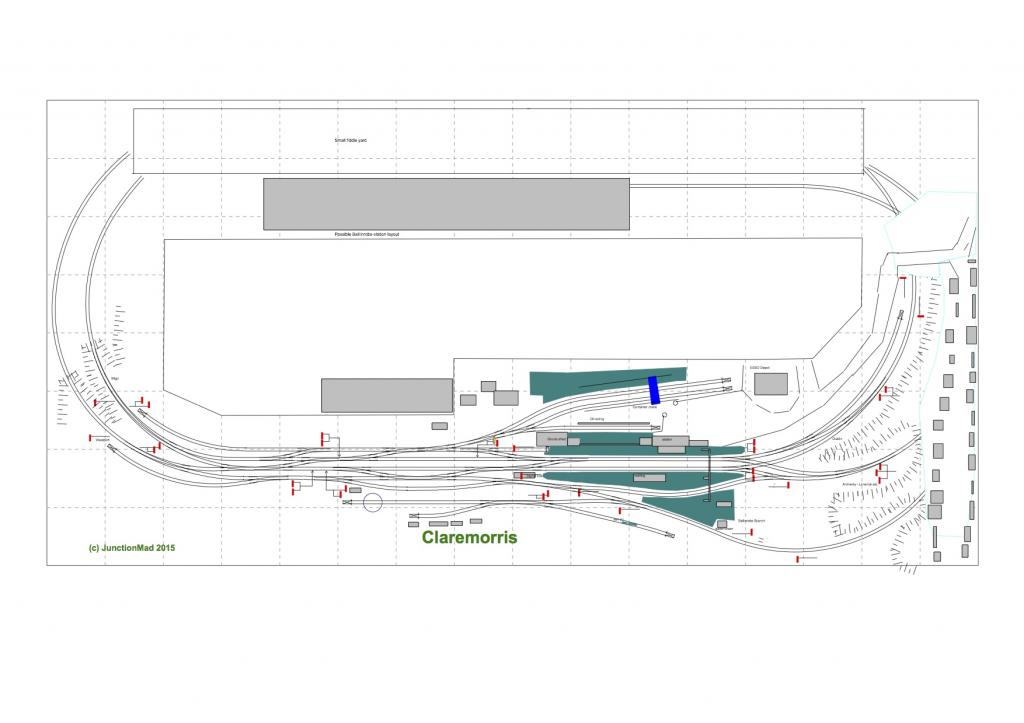
Hi foilks , how that I have the space, I can plan in earnest. I attach a outline track layout based closely on the prototype, track layout around 1970-80. Ive moved one crossover and some of the turnouts are on curves unlike the prototype , but all the track formations/movements are per the prototype. layout is 16' by 8' , no curve under 2'10" and all points 1:5,1/2 or greater Ive taken a few liberties with the town representation and the station road access Ive signalled the ballinrobe branch for passenger working as per an old signal diagram I came across. Im going to operate the Ballinrobe branch as if it had survived into diesel passenger service ( plus I can justify running a few steam locos if I want to.) I attach the PDF Id appreciate any feedback . I plan to build the turnouts in 00-SF ( 1mm flangeways ) and use C&L oo track for visible track and keep the PECO code 75 hidden ! Given I had to shrink the length , Im still looking at exactly how a freight train , that is Dublin or Limerick bound would be extracted from the goods yard , I suspect the main lines would be used in the model for the loco run round, whereas the real thing might have enough space to do it in the loops its a big project and will take me a long time, its will be DCC from the start , but with MERG CBUS for layout control ( as well as MERG DCC controllers ).

-
it traditionally was used with rheostat controllers, its far less useful with solid state devices. It relies on the transformer being truly floating , so that in effect one transformers GND can be lifted up above the other to allow the correct currents to flow to the respective controllers. Persoanlly I think its a nonsense process, when a simple DPDT switch will keep everything seperate. It also generates issues when you have a common power supply, so again you have to check and KNOW that the PSU in a double controller etc is actually seperate and not commoned
-
Sorry, let me state first that Im a practising electronics engineer, and I write this surrounded by a considerable rack of test equipment Firstly its not all all uncommon , in the absence of double insulated transformers, that the 0vdc is connected internally to the mains protective earth Contrary to you comments, since no current path to earth exists , then this wiring will NEVER affect the RCD, in normal non fault situations . ( The RCD detects imbalances in Live and Neutral , and is not affected by DC currents on the secondary side of a transformer There is NO requirement in the EU , that double insulated transformers HAVE to be used in low voltage power supplies . Some are and some are not. typically in small PSUs, that power iPhones and the like, you will get double insulated, but any PSU, with a metal earth pin, is likely not to be double insulated. larger switched mode power supplies are often not double insulated The reason that the earth is connected to 0VDC is to ensure that a reference ground is maintained. This prevents the 0VDC line from floating above earth potential, which can cause common mode voltage issues, where you connect devices that are powered by their own transformers, together via a DC connection , a classic example would be comms busses etc. This is why the ATX spec for PC psu's had DC GND connected to earth so you may find both types. As to feeding with different transformers, yes no problem, but not as was suggested with SPDT feeding a SINGLE DC Track section, which anyway is not something you want to so anyway
-
Dubray books is listing it cheaper then amazon
-
truly DCC is much simpler for any sort of decent sized layout. DC requires too many switches and connections etc to try an simulate prototype movements
-
you cant even be sure , in that case, as most transformers, have the 0vDC lines referenced/connected to earth to prevent floating common mode voltage issues. Hence there is a common path for the short through the mains earth wire. IN double isolated systems it will technically work, but its really bad practice, because the 0VDC of one of the controllers will be lifted up by the voltage from the other isolated controller and so will anything connected to that 0Vdc ( accessories etc ) basically it not a workable solution, use DPDT switches
-
Im trying to gently get him to see the error of his ways In fact you dont need both controllers powered on,( i.e. throttle advanced ) because in a standard emitter follower ( series pass) DC controller, there is a constant path to the OV line, even one controller has its throttle to zero, the other controller will be staring into a 0V line dead short. fundamentally , there is no common rail in a DC system, both rails can assume both polarities ( at different times ) DCC is different, it will work in that case ( though its not of course necessary )
-
hmm. if you wire standard DC controllers through a SPDT switch and common the other wire ( as per the diagram shown previously ) , these controllers , reverse by using their own DPDT switch, so if one is reversed and the other is left in forward. Then you will have the positive of one controller directly connected to the 0VDC of the other. (via the common unswitched wire ) You cant use common rail in this situation IMHO ( it can be fudged by adding the reversing DPDT switch after the SPDT controller selector switch of course, but thats not typically how this DC controllers are put together )
-
Thanks RL, how did you feel about the lack of embossed relief in brick papers. My previous efforts used either embossed card, embossed plastikard or DAS ( scribed) . My problem is painting the resulting model as I could never get the colouring right. now Im considering trading the embossing for better colouring
-
huh, what happens when you reverse one controller and not the other, in a rail common situation
-
talking about card, anyone have experience of using ink jet printed brick/stone papers. I was going to experiment with this method, as compared to using scribed DAS clay walls just to see comparison in 4mm.
-
I would question this "Built primarily to provide a passenger service, the railways of Ireland...." Most railway companies in ireland justified their investment on freight , especially animal traffic , passengers were somewhat of an afterthought
-
once you have a DCC controller/booster connected to the track , you have a DCC layout. Once your locos are " chipped" they are DCC ready. no reason why you cant run in on DCC. or if you have a little test track on DC, just remove the decoder. I really wouldn't bother with trying to run DC on DCC in DC compatibility mode. Lifes too short.
-
Use of sanding on irish railways
Junctionmad replied to Junctionmad's question in Questions & Answers
hmm. I know track circuits and leaves are a big issue. But track circuits have been around a long time, well into steam sanding era. perhaps , its as you said the freight tonnage was just small beer. But you would have thought that the beet trains would have been ideal candidates I know about the use of Sandite, But the use of sandboxes on UK diesels does seem reasonably common -
Greyboard is " mounting board" , widely available I think we are all passed the cornflakes box stage , I hope. The card is poor quality
-
Use of sanding on irish railways
Junctionmad replied to Junctionmad's question in Questions & Answers
Given I beleive sanding and loco based sandboxes is still used in the UK. It's funny that irish railways practice differs. I'm always surprised at how NIH ( not invented here ) is very prevelant on irish railways. -
Always perplexed me why cie/ir/ie. Forbid the use of sanding , it must have been widespread on steam locos in Ireland and it has remained in use in the US and elsewhere. Anyone shed any light on the purpose of the decision not to use sanding apparatus
-
pictures wanted of CIE ground signals
Junctionmad replied to Junctionmad's question in Questions & Answers
Thanks. How did the wire attach. I originally thought the weight arm was cranked but not obvious in your picture -
pictures wanted of CIE ground signals
Junctionmad replied to Junctionmad's question in Questions & Answers
great thanks, any pics of the operating lever side !!, -
pictures wanted of CIE ground signals
Junctionmad replied to Junctionmad's question in Questions & Answers
thanks, knew about SSM. I think I can do better with Shapeways and its a useful CAD exercise. any pics?