murrayec Posted July 6, 2020 Posted July 6, 2020 2 hours ago, KMCE said: Many thanks Eoin, I will bring them along, and will also bring the DSER Armoured train as well - it's nearing completion & still unpainted, but I'm sure it will be grand. Ken Excellent Ken Shall see you then Eoin 1
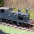
KMCE Posted July 8, 2020 Author Posted July 8, 2020 A shippment this week from Alan Gibson allowed me to get some wheels onto the chassis. As with other chassis, this one is compensated with only three fixed axles out of 6 - centre driver, for the motor & gears, leading bogie and trailing axle of the rear bogie. Coupling rods were also articulated to allow movement across the driving axles which can be seen here: Chassis is a little nose heavy in this configuration, but this will be sorted once all weight goes on. With the body added, it gets tail heavy, so bogies are necessary to level things out. Leading bogie was to have hornblocks, but given the articulation around the fixing point, I figured it was unnecessary, so solered in some 2mm chassis bearings instead. The front bogie is compensated with the leading driver, which was a bit tricky given the chassis construction and front foot plate. If I was doing this again, I think I would re-design the front compensation to make it eaiser to fit. This shot also shows how the cylinder wrapper does not completely cover the cylinder housing. A bearing pad was added to the front of the compensation rod to allow the bogie to move. A bit of PB wire will be needed to encourage the bogie to stay in line with the chassis, however it does seem to perform reasonably well as is, given the distribution of weight between driver & bogie. Next up was the rear bogie. This one has a fixed axle at the trailing end - I was looking for some stability when operating bunker first, so compensation was added to the second axle. This axle is held with hornblocks and a compensation bar fixed to the bogie cross beam - the bar was offset to allow the bolt for fixing to the trailing arm. The bogie was then compensated with the rear driving axle using 1.5mm tube and bent to shape. Again a bearing pad is used on the bogie trailing arm to allow for movement. This bogie will definitely need some wire to guide it as it is quite free to move around. OK so now we have a rolling chassis, albiet with some minor binding between the coupling rods and centre axle hub - some shims on the crankpin should sort that out. As mentioned in a post above, the rear wheels impact on the cab, and a cutout was needed to accommodate this - quite a deep cutout it transpired. This allowed the body to go on and after much tweaking of the front and rear compensation to get the body level, we now have some semblance of a locomotive. Boiler was removed to add the inner tank linings and a trim was added to the underside of the front upper footplate to match prototype. As noted above these footplate elements were quite flimsy and this trim helps to strengthen them. A quick shot with some wagons to get a indication of the size - this is a big locomotive! Cast parts are just sitting in place for the photos, and boiler has not been fixed back in place, hence the gaps Thats all for now. Ken 7 4
Galteemore Posted July 8, 2020 Posted July 8, 2020 This is very fine work, Ken, and a most inspiring build. Carlsberg don’t make WT class tanks but if they did.... 2 1
David Holman Posted July 9, 2020 Posted July 9, 2020 Splendid and clever chassis work. As you say, a big loco, which means a lot to think about. 1
KMCE Posted July 20, 2020 Author Posted July 20, 2020 So, in a case of one step forward, two steps back, I needed to revisit the boiler and smokebox. The original etches provided a long boiler with two layers laminated over it to create the smokebox. This created a number of problems for me, one the layers started to delaminate as I was working, so figured the level of heat required to ensure three layers were complely and securely fixed was more that my iron could comfortably provide, two, the smoke box was too far forward on the chassis. A third problem was the thin nature of the boiler etch which took some damage when I was cutting out the slot for the motor. So back to the drawing board and my preferred method for making boiler & smokeboxs - former and wrapper for smoke box bolted to a separate boiler. New parts cut for fresh boiler and shortened smokebox: Nickle silver parts were created for the valve gear support (more later) Smoke box backplate with boiler fixing nut and spacer added. Threaded rod & nuts allows lining up of the rest of the smoke box former. Circle of brass above the former is the front space and carrier for the smokebox door. New smokebox wrapper was rivetted, wrapped around the former and soldered. Boiler was wrapped around the semi circular formers with the full circle added to the front to allow bolting to the smokebox. All assembled and added to the firebox and fixed back into the body. This revised design allowed for a version of the smokebox saddle to be added which fixed those fiddly footplate elements and strenghtened up the front of the body. All good then ..............sadly no. The smokebox just looked too short. A distinctive feature of these locomotives is the large smokebox and this was just a tad too short. Given the construction, it was easy to make a new wrapper and redo the smokebox, and now we get this: Another element I wanted to sort was the positioning of the cylinders - they were a little too far forward, so some tweaking to the supports moved them back slightly which now look more prototypical. Now with a much stronger front end, and things looking more prototypical, I can move on to adding steam pipes, detailing parts and get started on the valve gear. All for now, more as time permits. Ken 7
Galteemore Posted July 20, 2020 Posted July 20, 2020 I can guess the amount of work you have summarised here, Ken ! More inspiration - and personally - very helpful information for me right now .... 1
Recommended Posts
Create an account or sign in to comment
You need to be a member in order to leave a comment
Create an account
Sign up for a new account in our community. It's easy!
Register a new accountSign in
Already have an account? Sign in here.
Sign In Now