Tullygrainey
-
Posts
934 -
Joined
-
Last visited
-
Days Won
55
Content Type
Profiles
Forums
Events
Gallery
Blogs
Store
Community Map
Everything posted by Tullygrainey
-
Perfect!
-
That is beautiful!
-
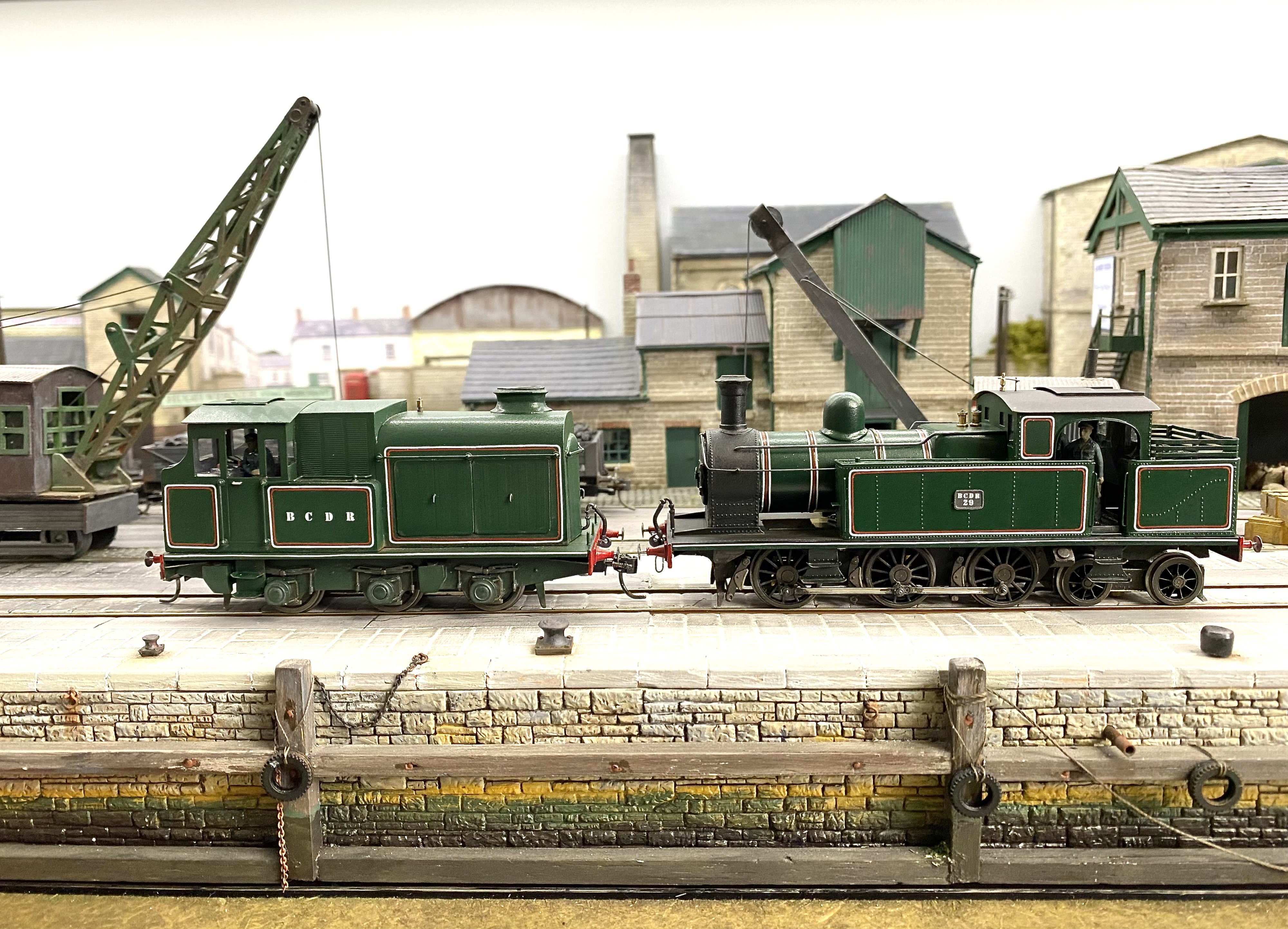
Thanks Patrick, and Happy New Year everyone The future’s bright. The future’s BCDR green Alan
-
Thanks David. Yes, the loco may be green but the air was decidedly blue here yesterday! And yes, I think we're looking at an enamel/acrylic reaction here. Clearly 3 or 4 days drying time for the colour coat wasn't enough! The fact that only one side was affected is odd but I think the culprit was an over-liberal dose of varnish on the affected side. For the record: the green body colour was Railmatch enamel, (GWR loco green 1601) the varnish was Humbrol Acrylic Varnish (Gloss 35) both applied from aerosol cans. The unaffected side shows it can be done without mishap but it needs care and plenty of drying time. Patience, in fact. I must order some of that Alan
-
Thanks GM. You’re right and I do need to walk away for a while or risk making it worse. Cheers
-
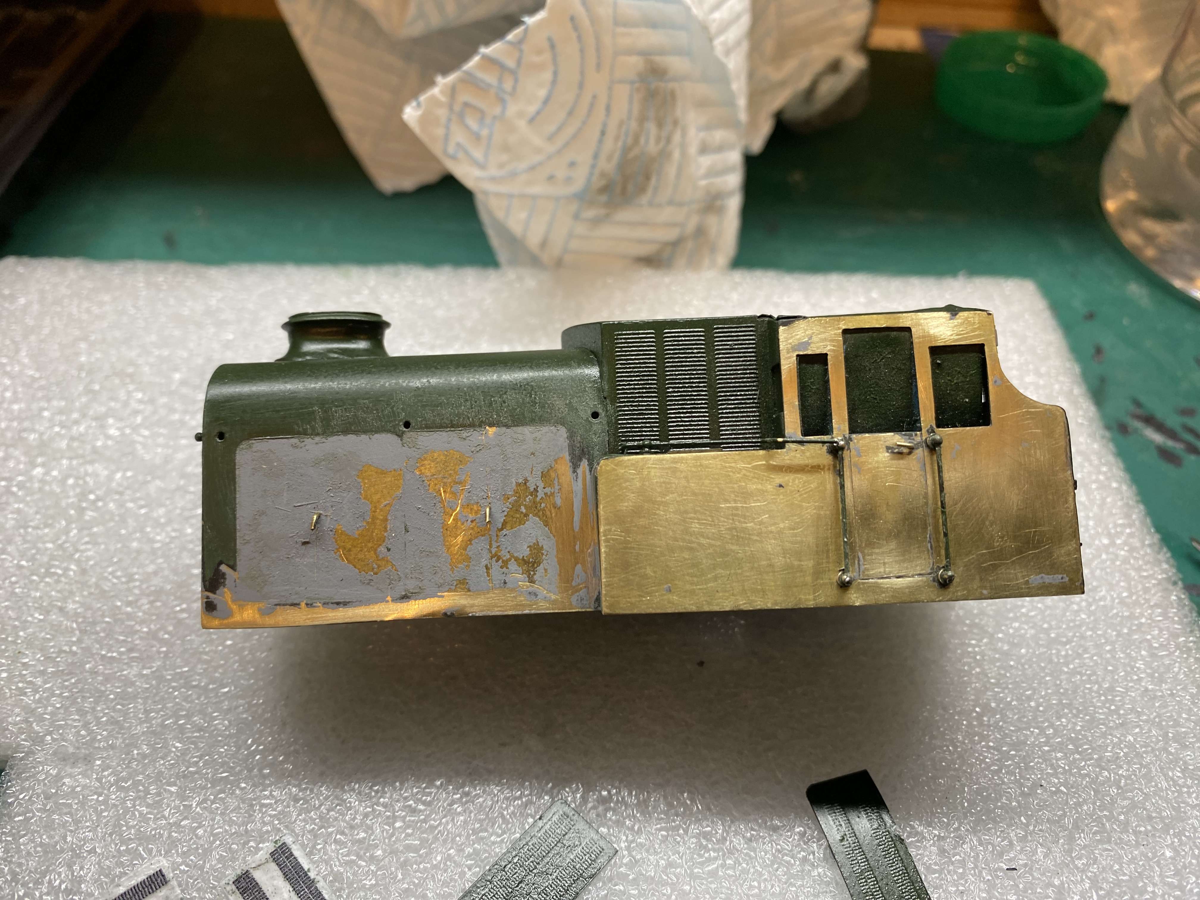
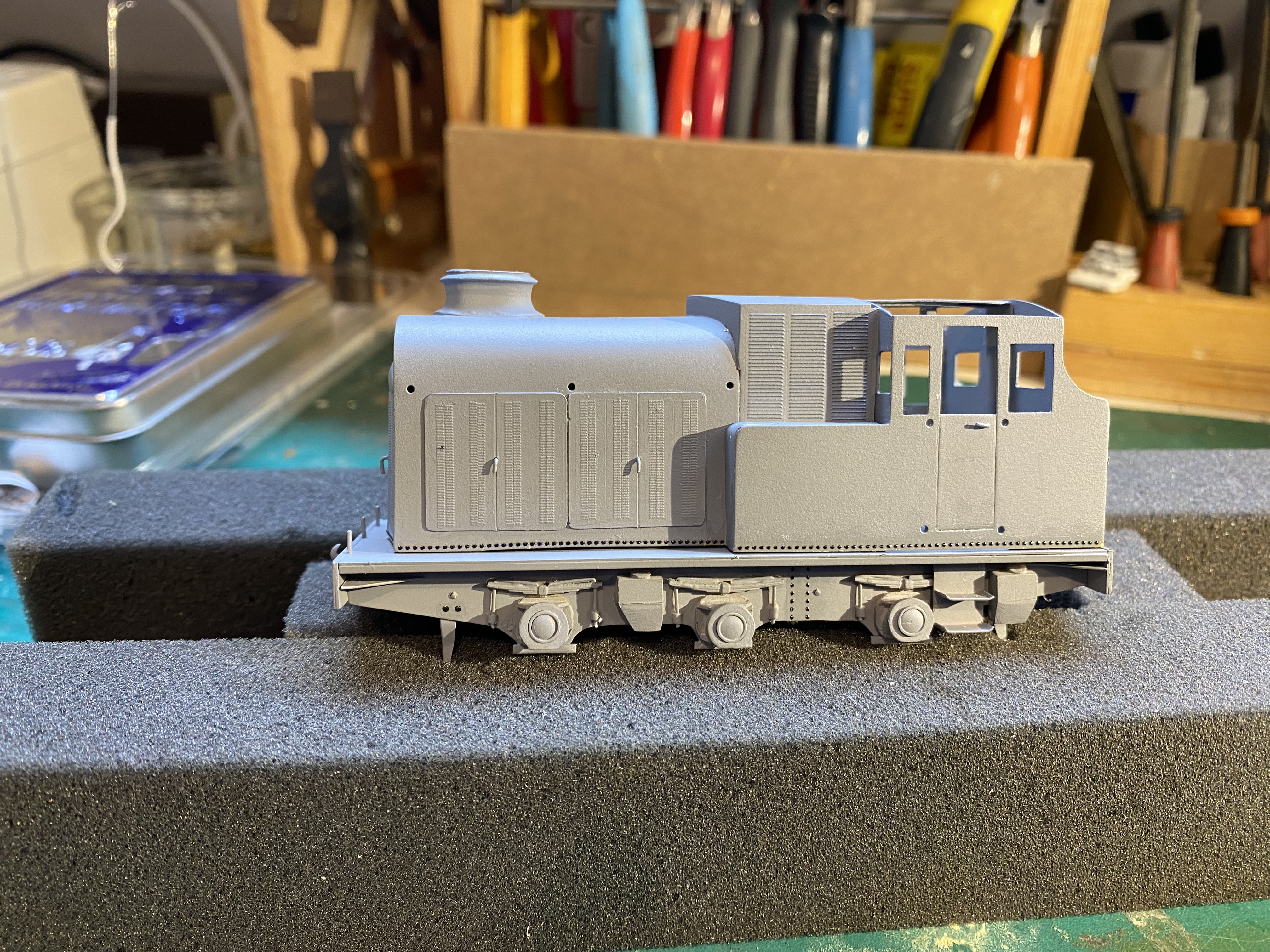
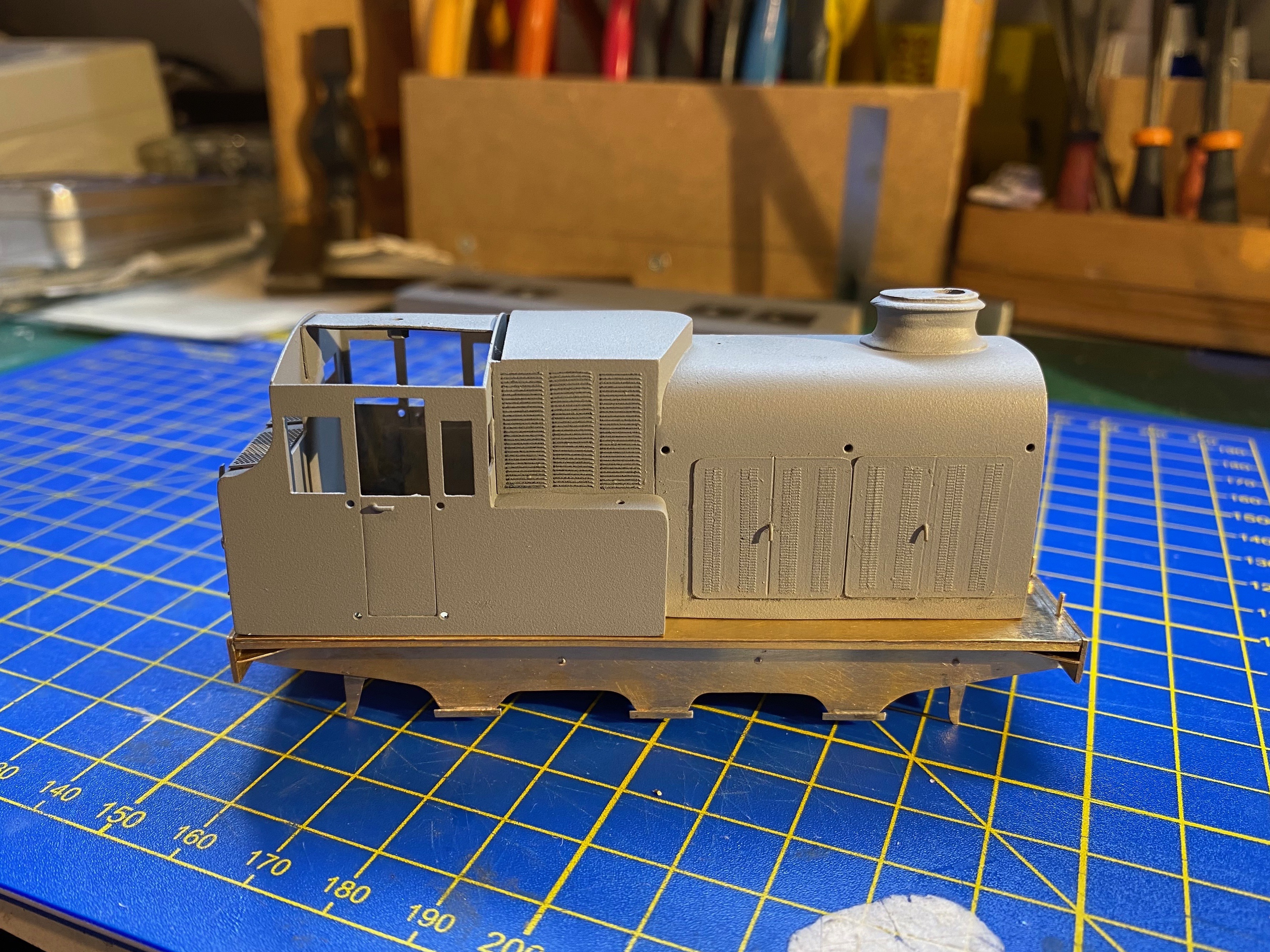
I decided to take the easier route and stick with what I know, using transfers for the lining. I was making good progress with the paint - a nice even coat of GWR green overall, left to harden for 3 or more days. Then a dusting of (acrylic) gloss varnish to provide a good surface for the lining transfers. And that's when the disaster arrived. It crazed the paint - on one side only, strangely enough. Trying to sand it out proved futile and I've now taken it back to the metal in places. The engine casing doors, complete with louvres proved unsavable and will need to be remade. Also the rivet strip at the bottom. It's going to be a challenge to blend this back in. I've so far resisted the temptation to bin it but It's certainly taken the shine off my day. Backwards and downwards Alan

-
Ingenious!
-
I'm enjoying watching this develop David. And I'm guessing it's been an enjoyable build too. I like your chassis and the Low Rider seems to fit the bill perfectly. Should be a smooth performer. I'm a fan of High Level's gearboxes. Best wishes, Alan
-
Wiggly tin is good
-
Looking forward to this one taking shape David
-
Yes. I've been thinking about trying a bow pen but there's going to need to be some practising done first! I've searched for smaller scale transfers but no joy as yet. Fox do some finer lines but not in the right colour, and no corners to match. Cheers, Alan
-
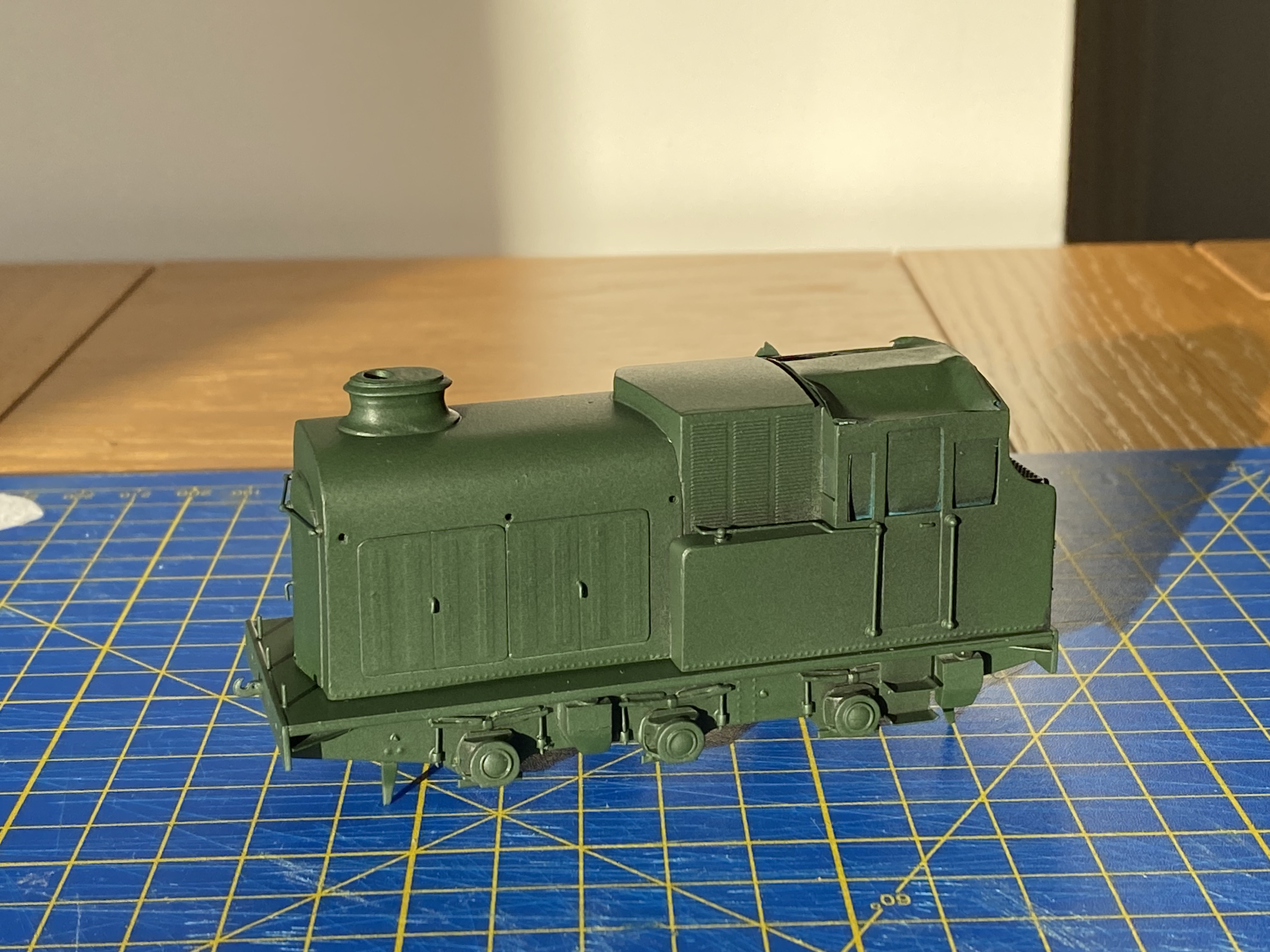
I'm approaching the painting and lining out stage with this project. My previous attempts at BCDR livery have involved red and white lining from Fox Transfers applied separately over Railmatch GWR post-1928 loco green (undercoated with Halfords Matt Black to darken the result). But even at 0.33mm, the lining is a bit broad and over-scale. I'm happy enough with that but are there other options that would produce a finer result? Grateful for any advice. Alan
-
Thank you Patrick. That's a nice idea. Maybe with a couple of Hattons Genesis coaches, suitably tweaked? I ordered a set 18 months ago and Hattons were finally able to despatch them last week. According to Royal Mail tracking, they've been at Warrington Sorting Centre since then, no doubt at the bottom of a very large pile of parcels. I suppose a few more weeks is neither here or there Thanks John, and I hope you do. H&W diesels are a neglected species.
-
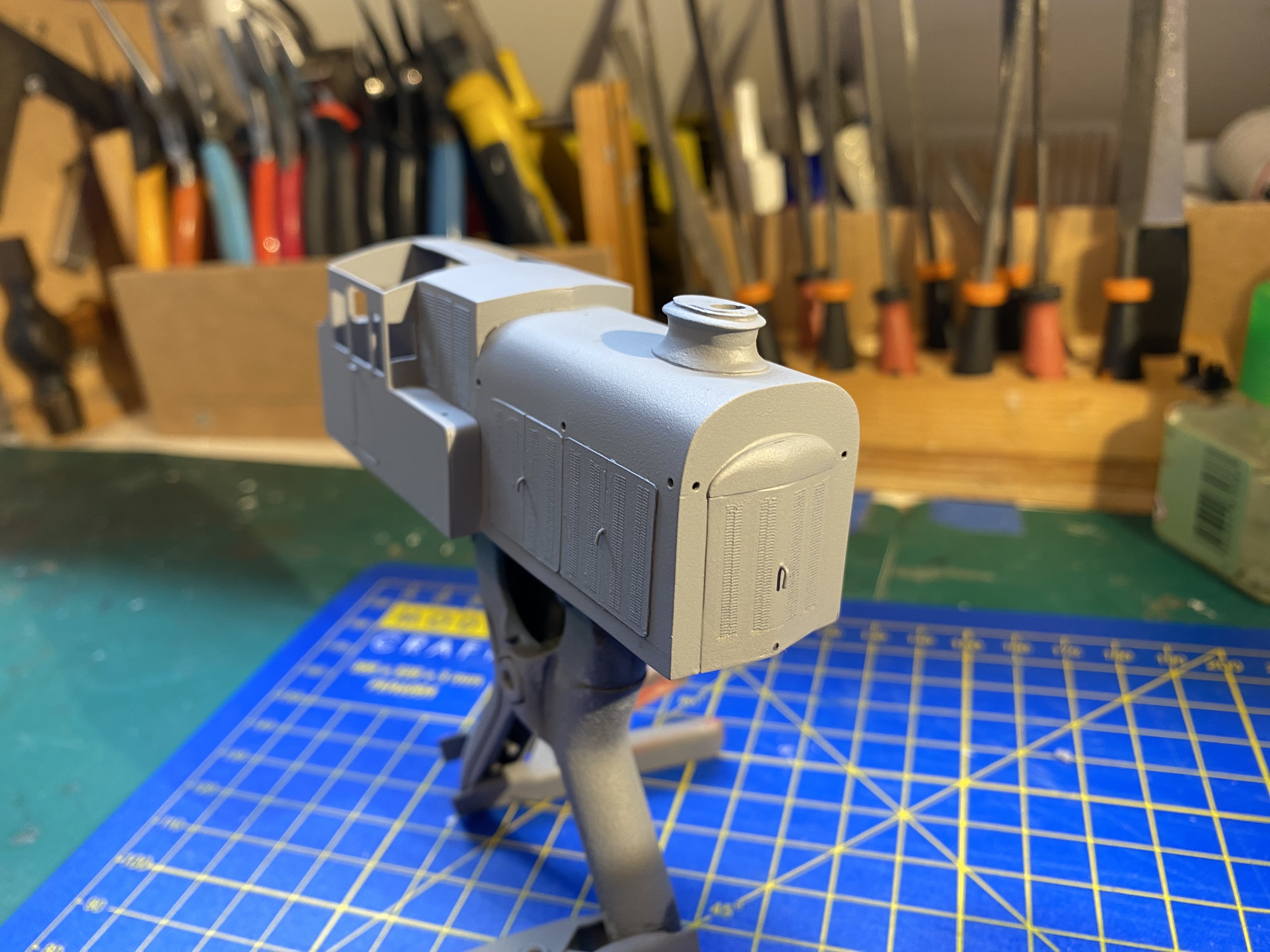
Onwards and upwards in small steps.. (and sand boxes and a few rivets) Alan
- 176 replies
-
- 16
-

-

-

Brookhall Mill - A GNR(I) Micro Layout
Tullygrainey replied to Patrick Davey's topic in Irish Model Layouts
Enjoyed your piece on Brookhall Mill in New Irish Lines, Patrick -
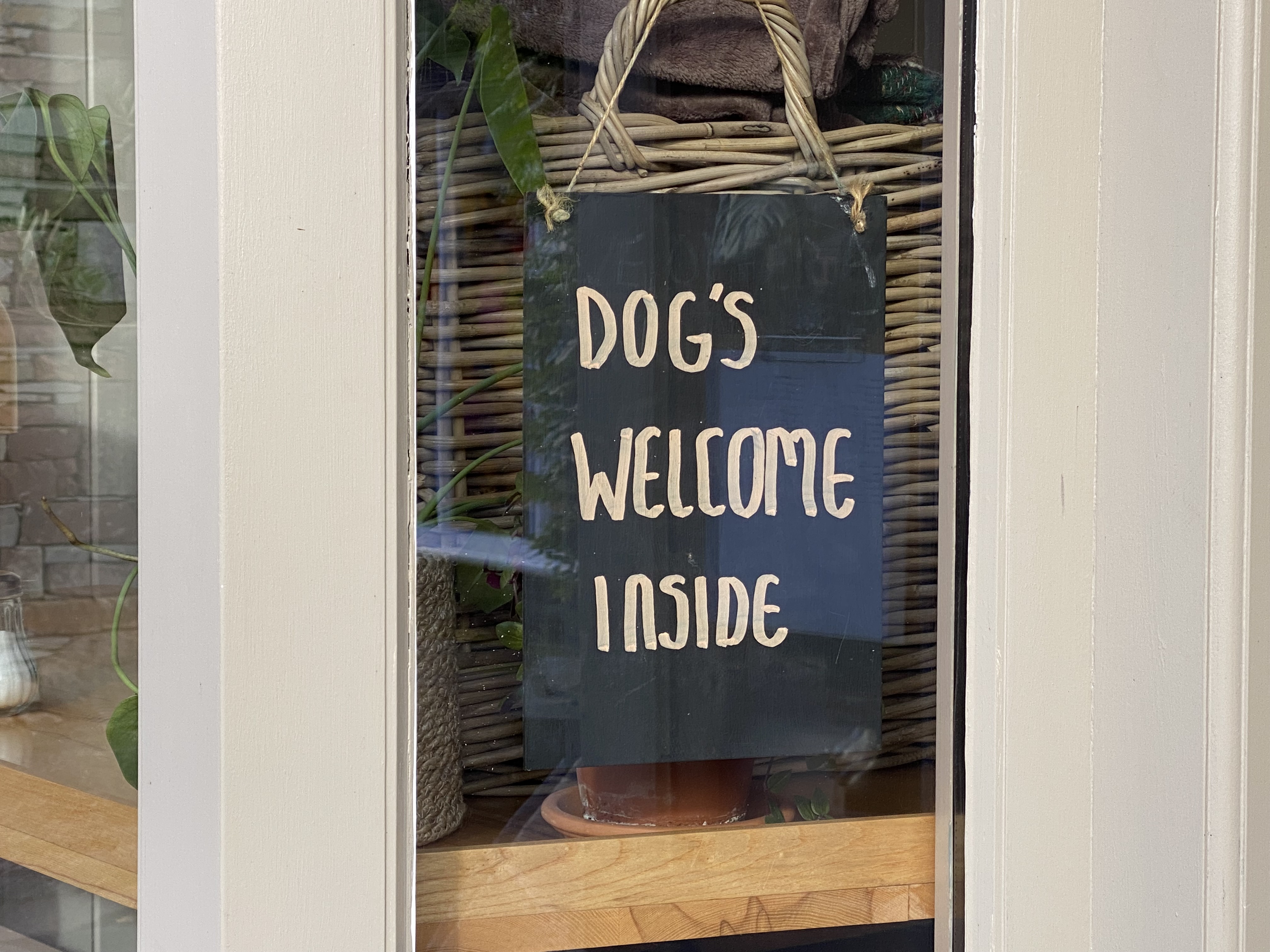
Yes! Mind you, the "if in doubt, whack one in" overuse of the apostrophe is possibly even worse. On a recent holiday in Cumbria, I came across this sign in a shop window. I assume that if you go in, the staff will lick your face. Or maybe bite your ankle? Alan
-
Brilliant! Wonderful atmosphere. Alan
-
Thanks David. I have equally baffling experiences in Currys . I browse there every few months or so in a gradually failing attempt to guess what all those black boxes do. Maybe it doesn't really matter
-
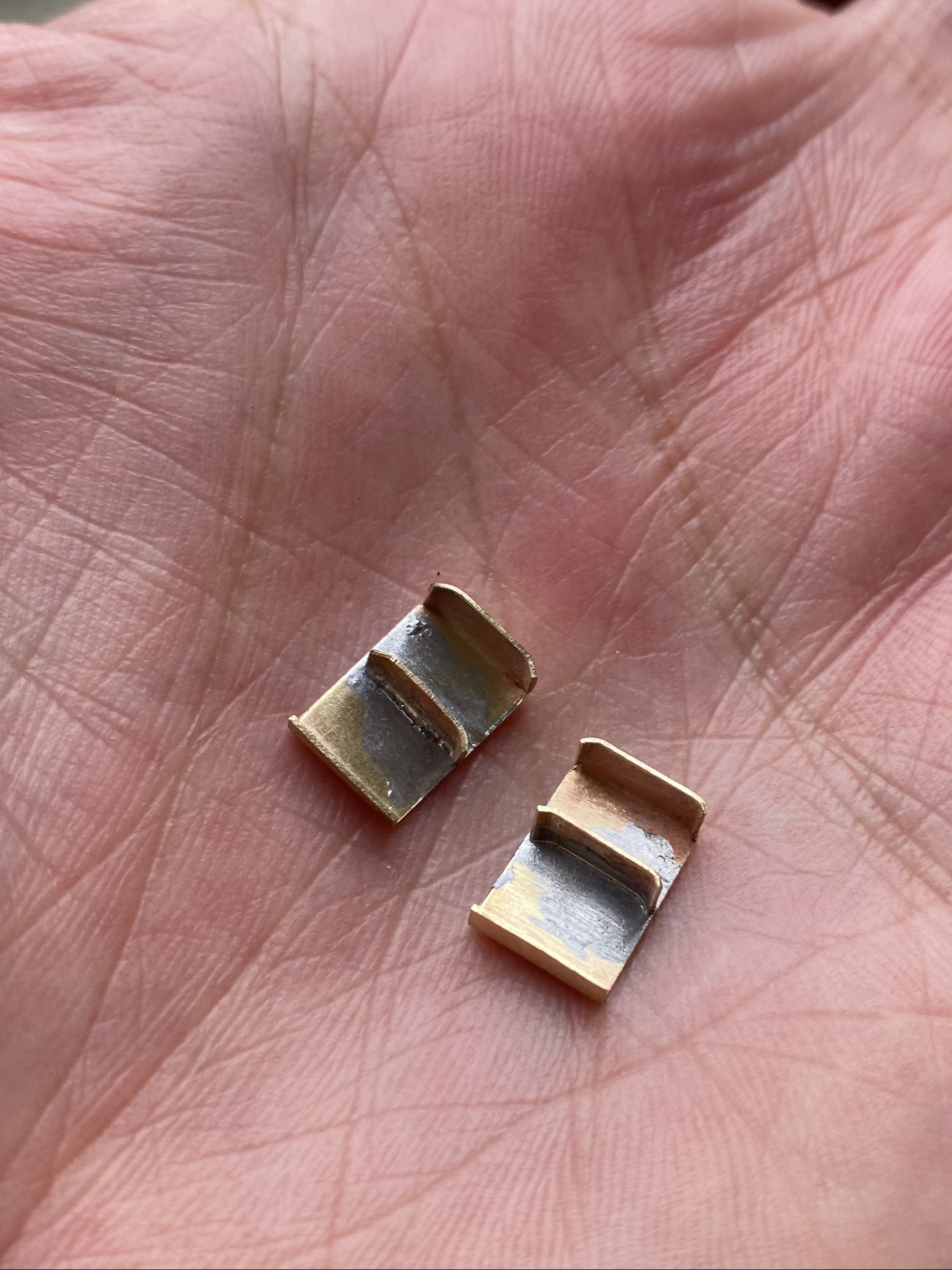
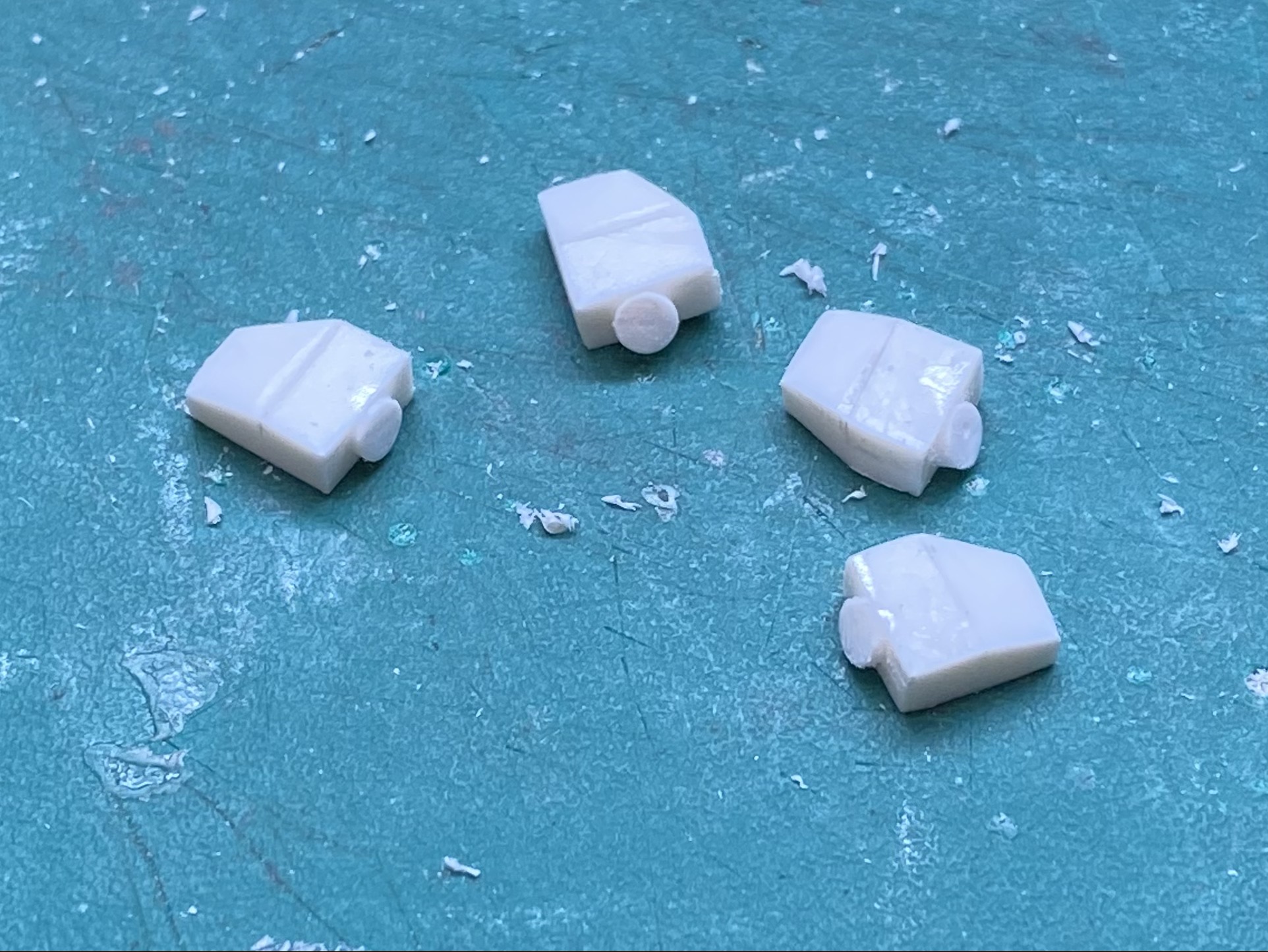
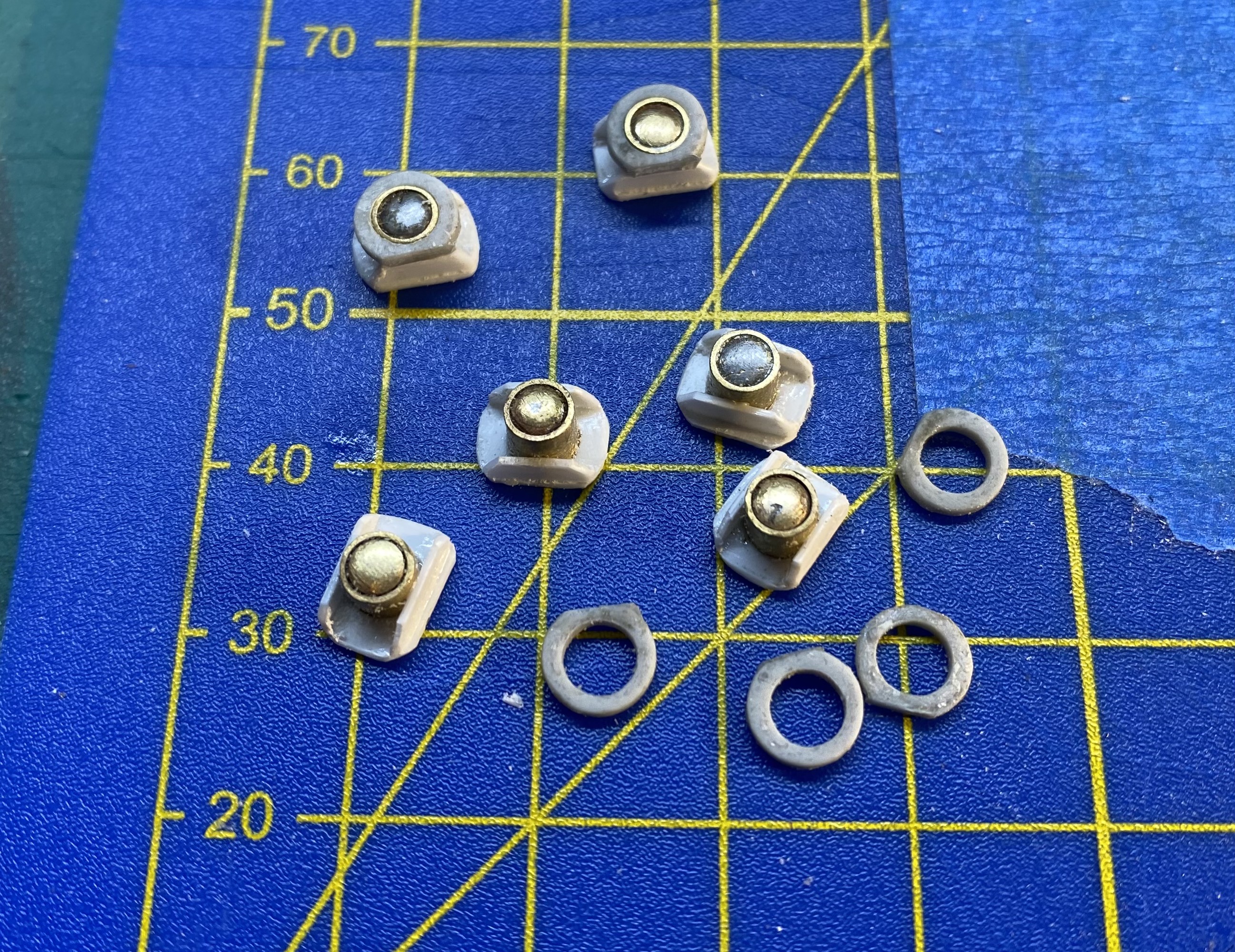
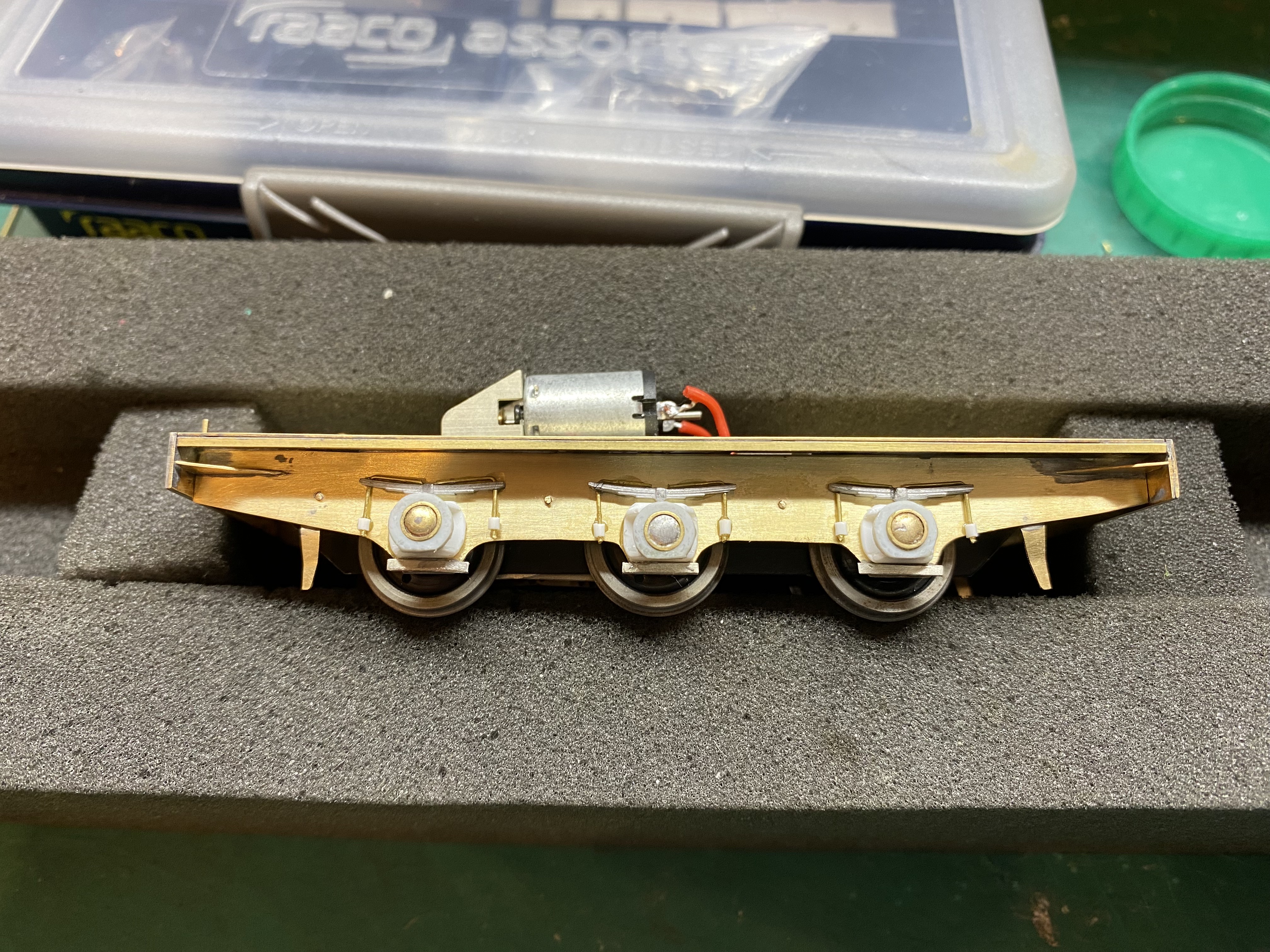
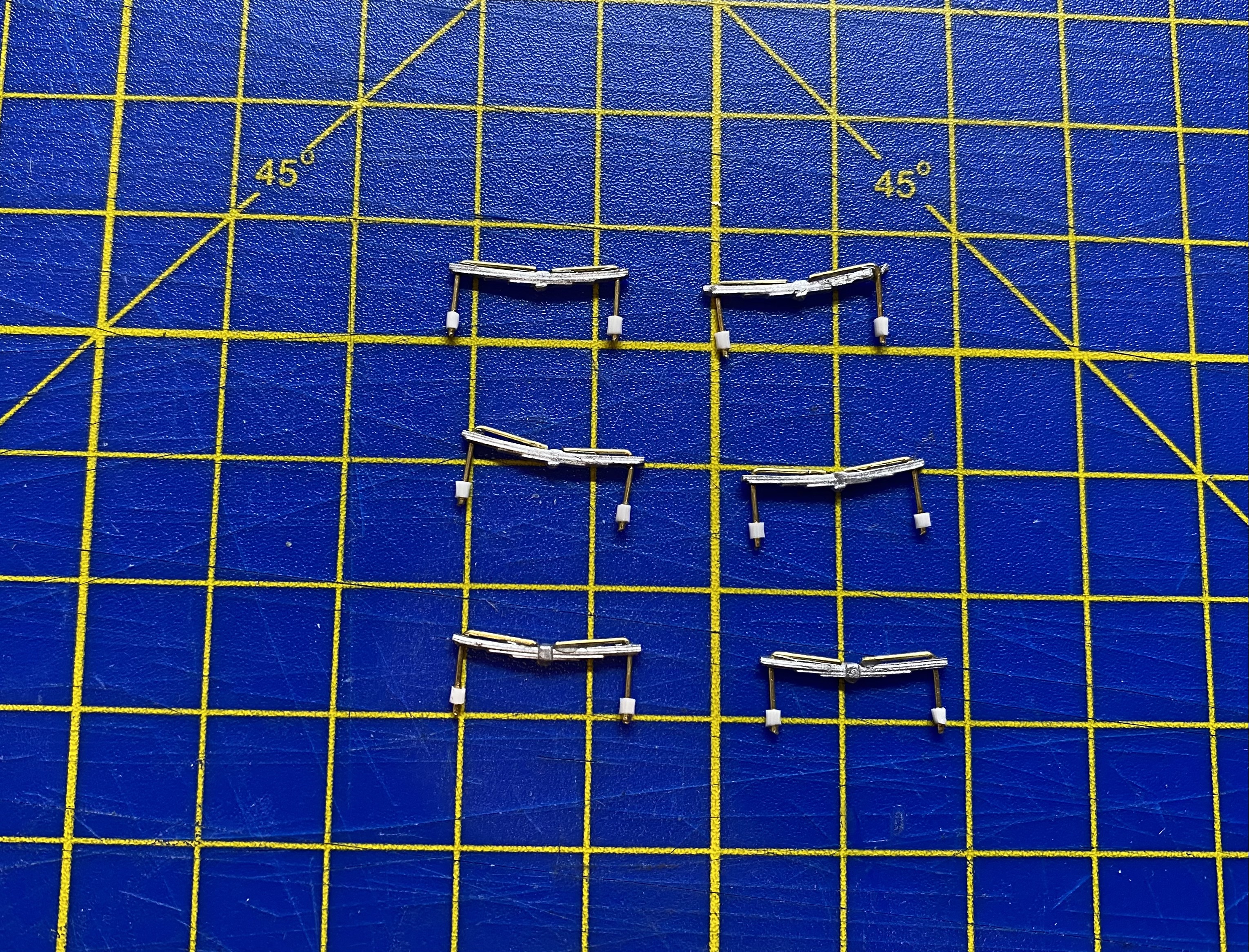
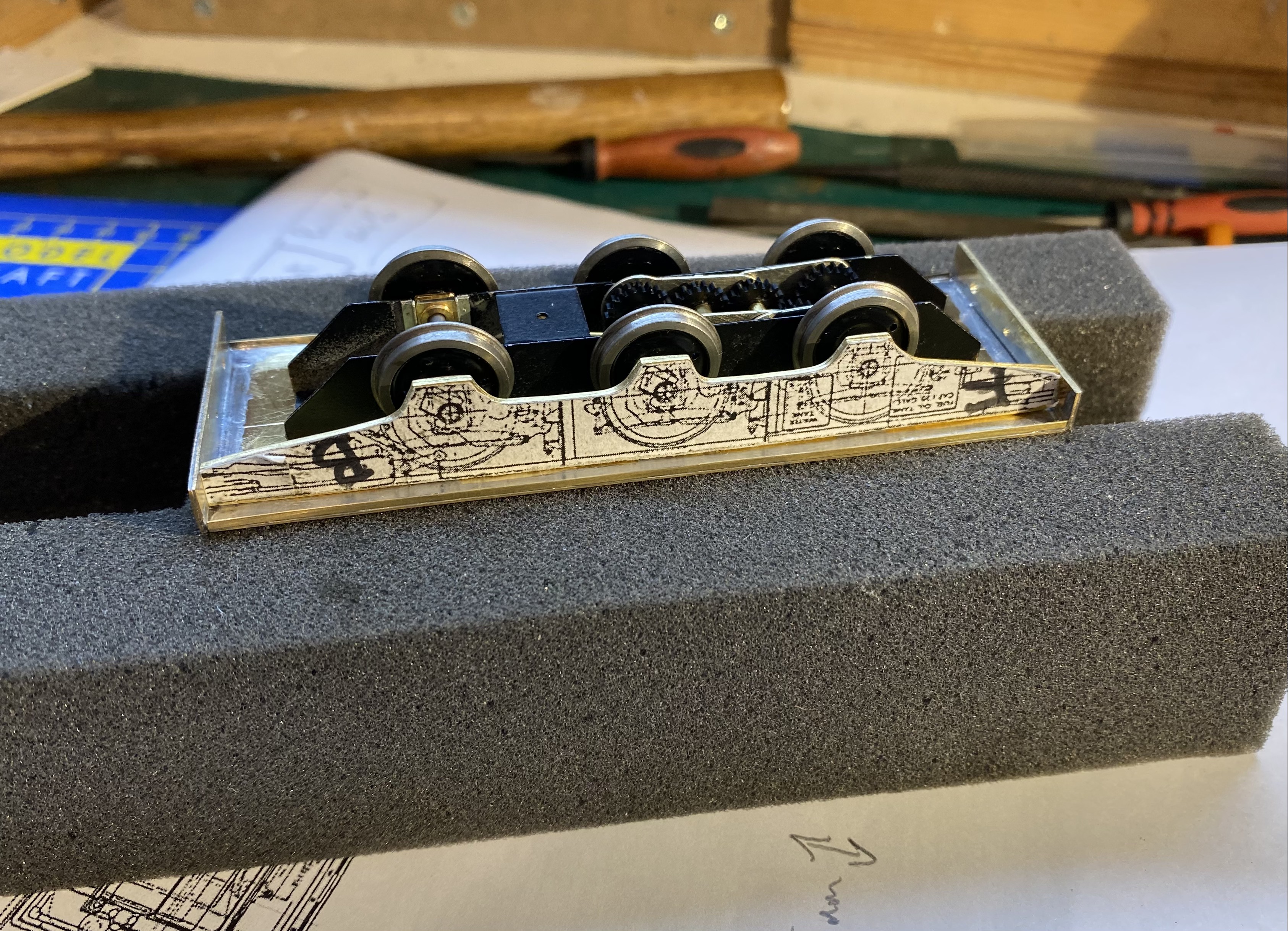
Some detail added to the frames. These bits are probably perfect candidates for CAD and 3D printing but since I haven’t plotted even the first point on that particular learning curve, it’s had to be old tech for this one. A rummage in my garage turned up some brass tacks (no, really ) with domed heads which, filed down a bit, could be soldered inside some short lengths of brass tubing to make the basis of the axleboxes. Plastic card and slices of plastic tubing did the rest. The springs were made using cut down MJT white metal castings (MJT 2258, GWR Spring Axlebox), 0.45mm brass rod and slivers of fine wire insulation. None of this is precisely accurate but close enough to convey a sense of the thing, I think. Onwards with superglued fingers, Alan
- 176 replies
-
- 12
-
-
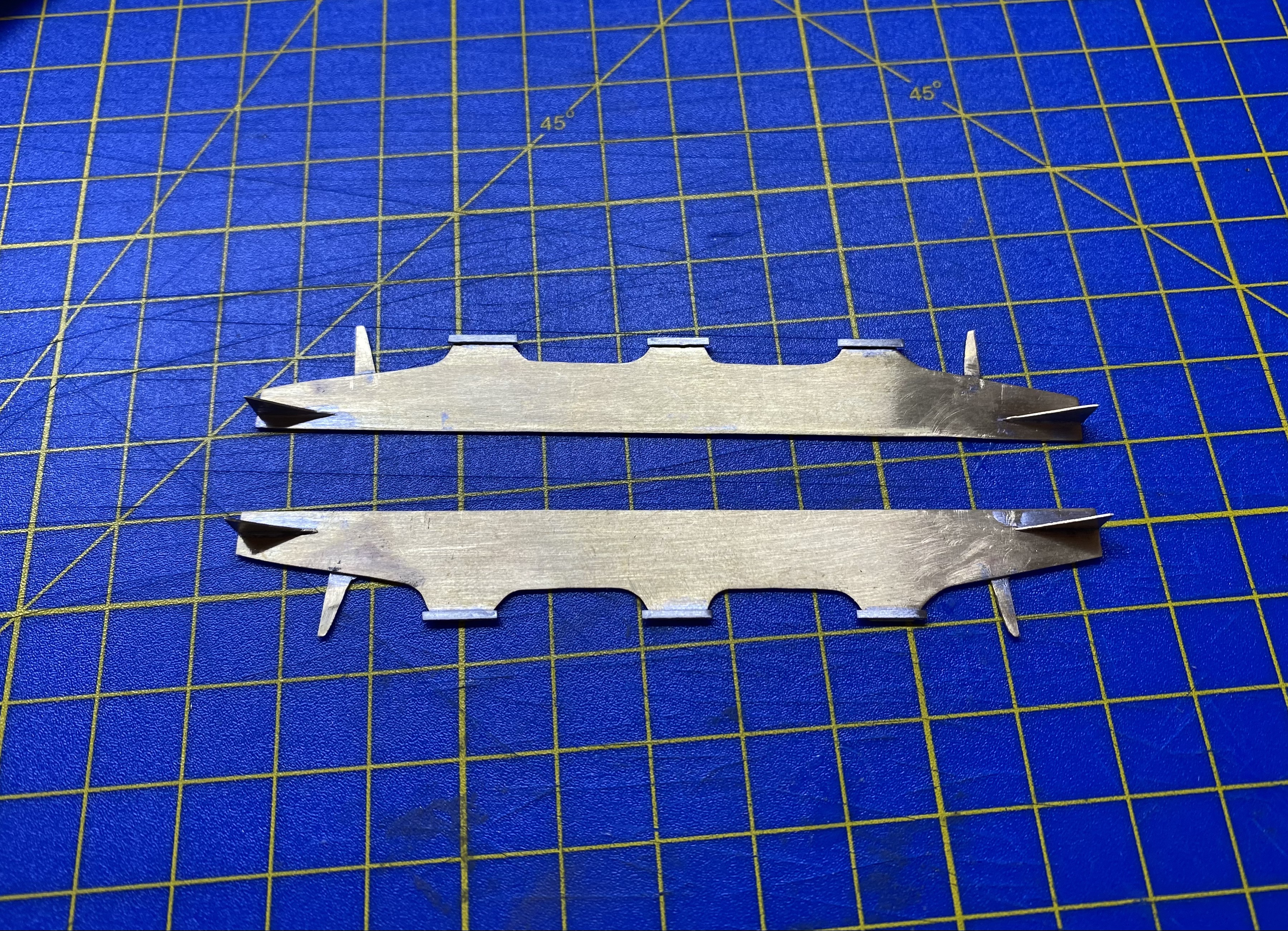
Frames separated and some details added before they got soldered into the running plate. Alan
- 176 replies
-
- 14
-
-

-
Beautiful. A really fine bit of modelling. Alan
-
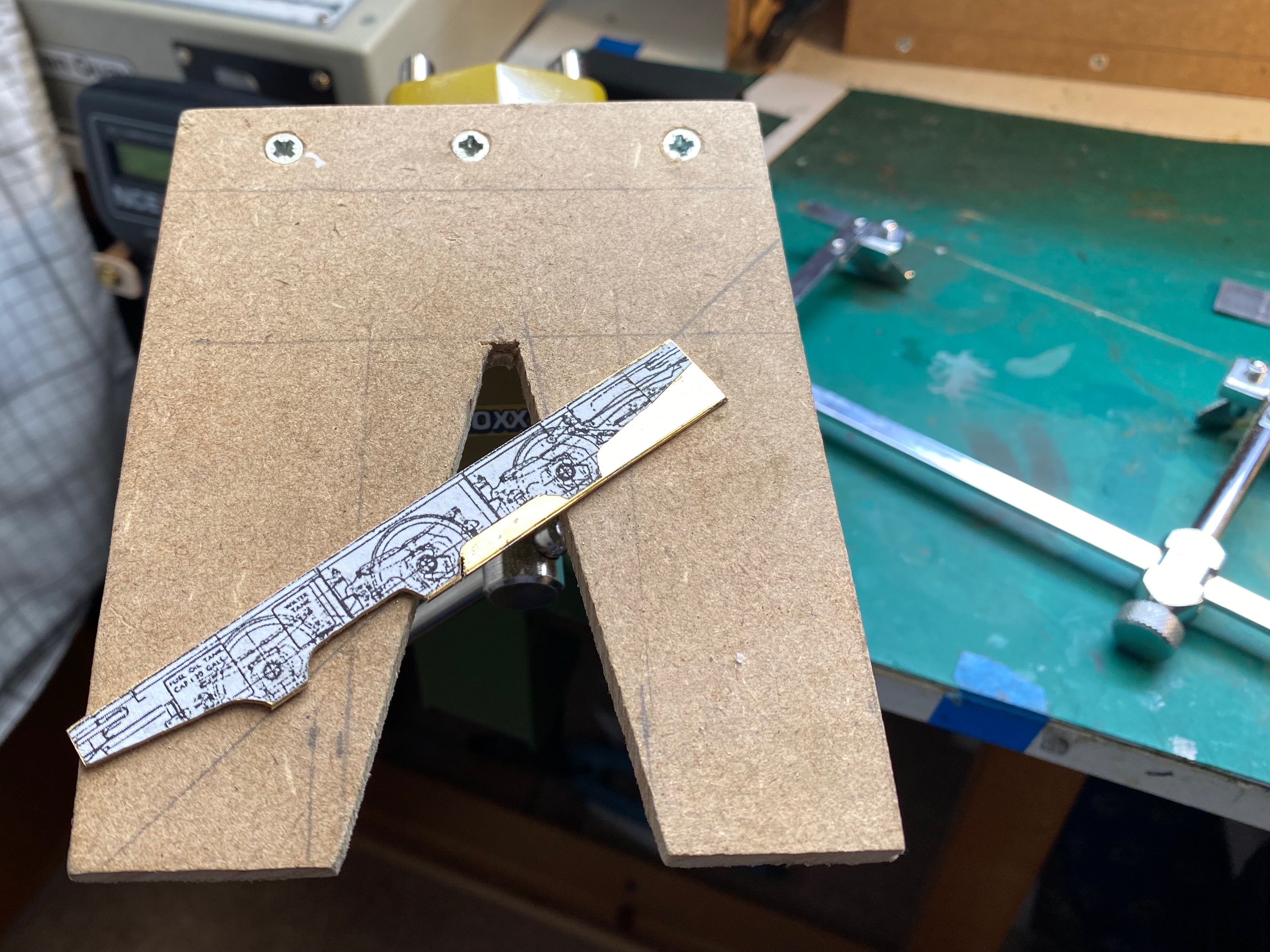
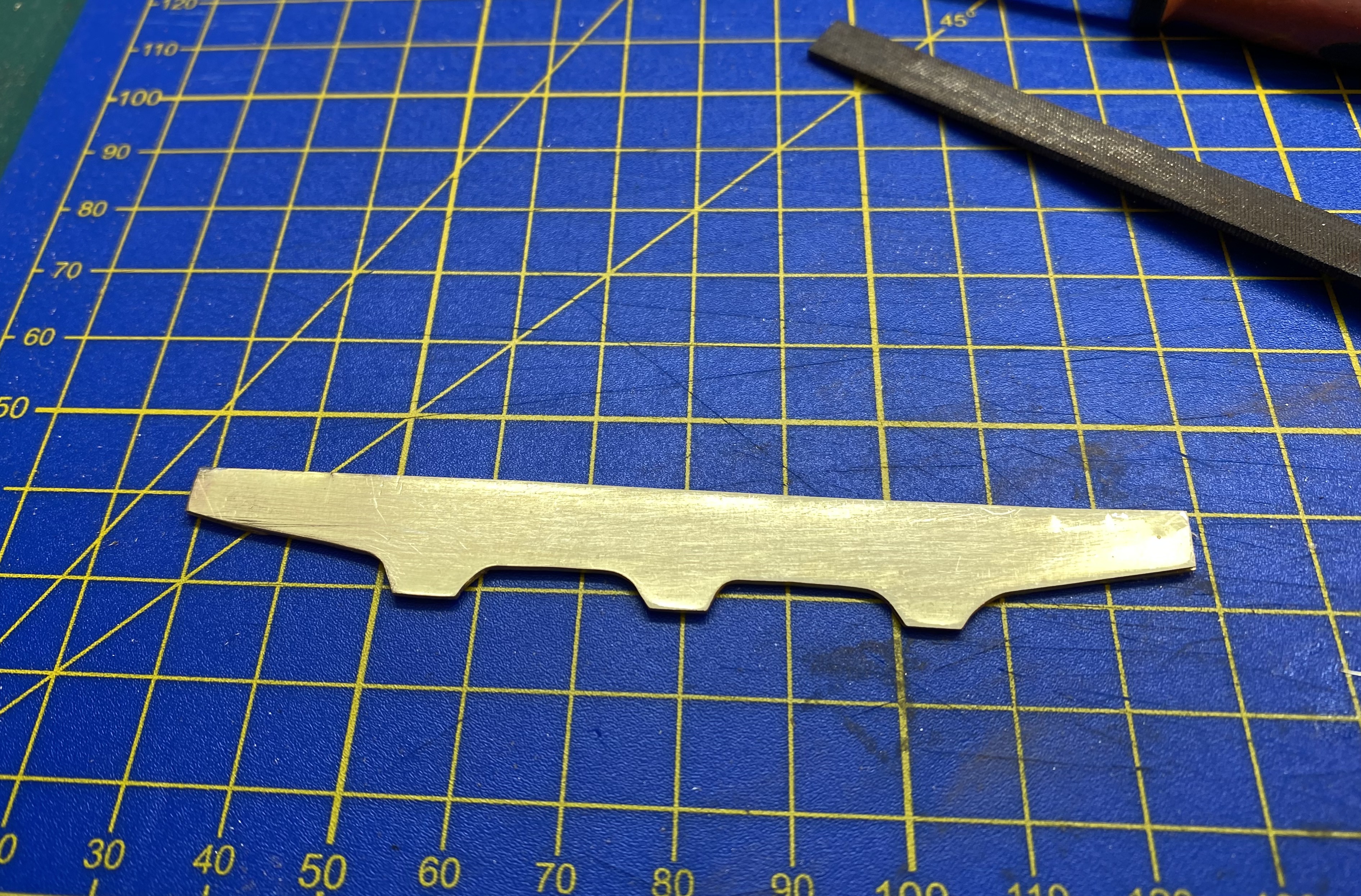
Piercing saw in play again. Outside frames cut as a pair. Some tricky stuff coming up soon - wheel hubs, springs and brakes Alan
- 176 replies
-
- 16
-
-
-
Predictive text at its mischief again I see, David
-
This is wonderful! A really fine piece of modelling at every level from research through to implementation. You deserve medal for the points rodding alone Looking forward to seeing it continue to develop. Alan
-
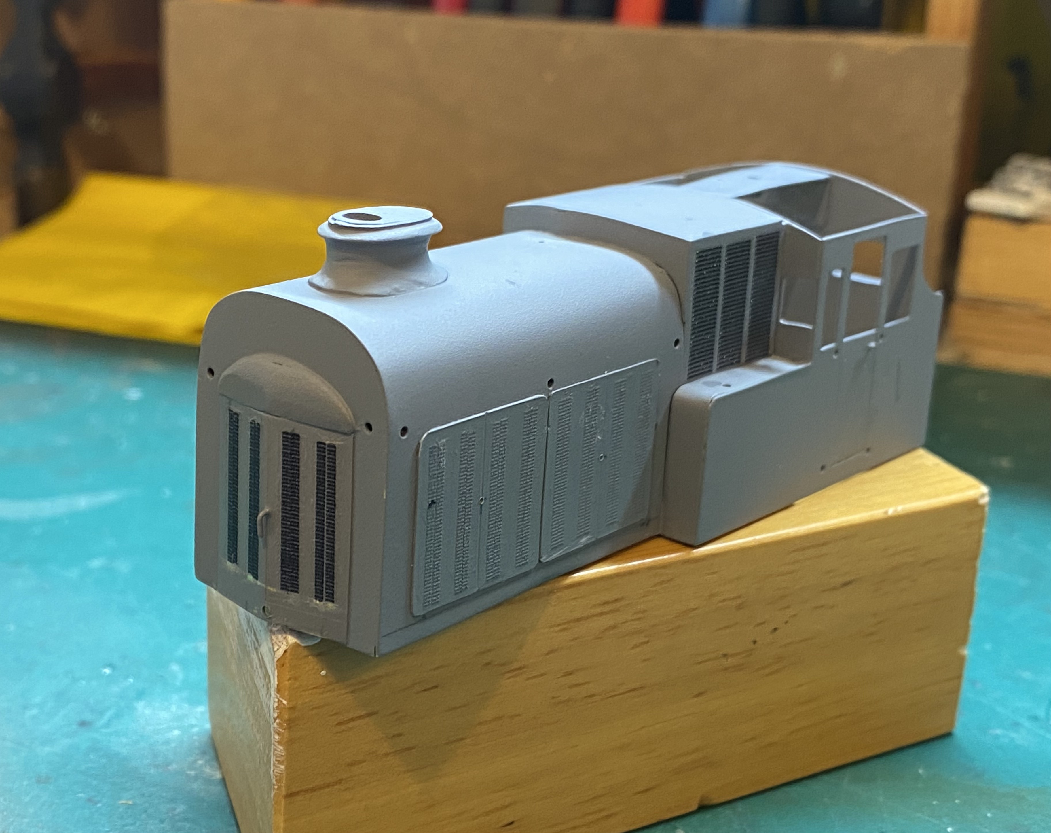
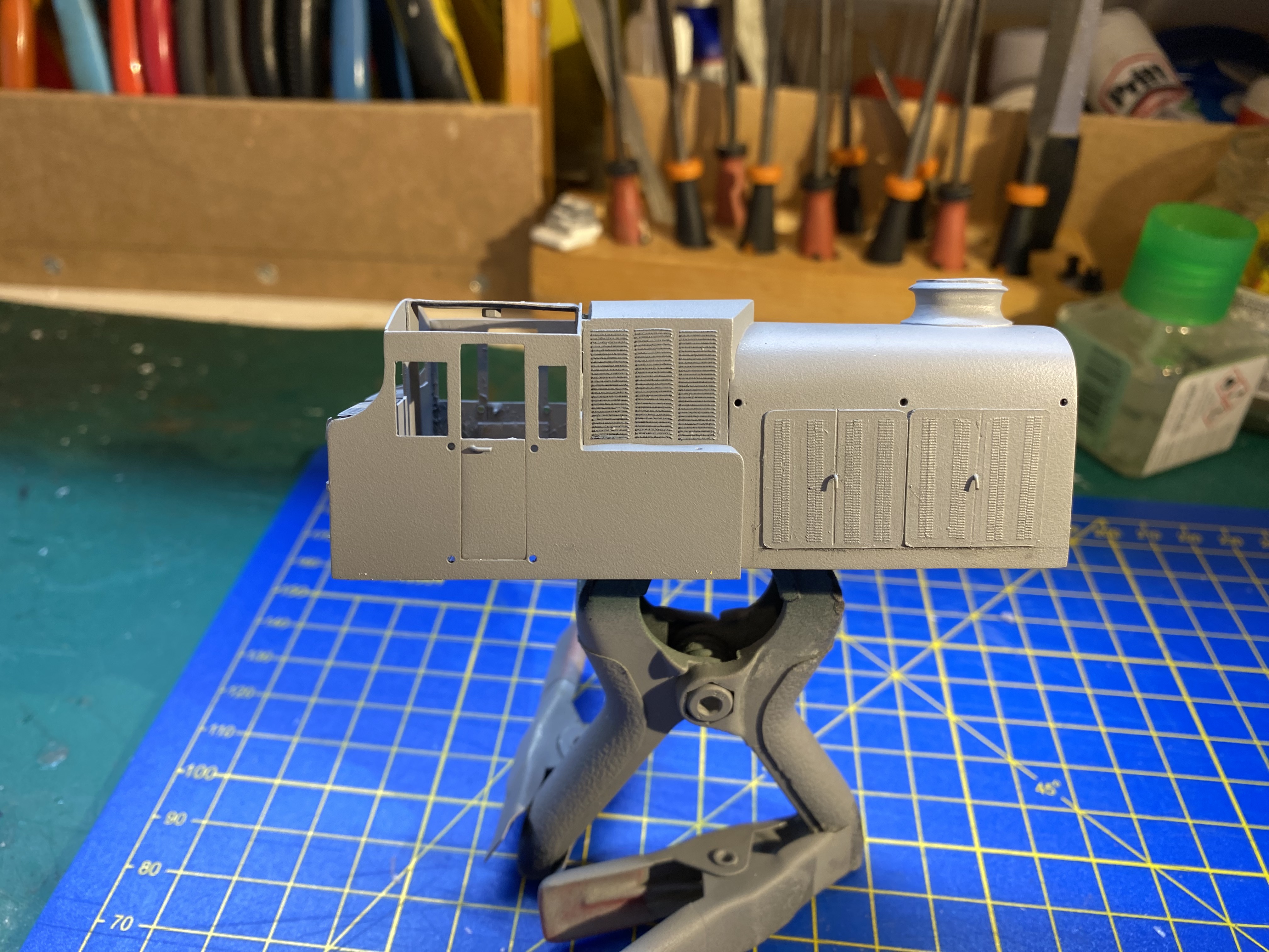
Well, we have some louvres at last. The Archer 3D resin transfers were tricky little brutes, very delicate and easy to break. One of the larger ones rolled up on me and had to be refloated to unroll it again. Then, eyesight being what it is, I couldn't quite make out which way up and which way round it was meant to go The narrow strips on the engine casing are actually 2mm scale and had to be doubled up to get near the correct width - a total of 40 separate transfers in the end. Not ideal, but passable under the two foot rule. All in all, it was a bit of an ordeal, given that I barely had enough of some of the sizes and little chance of getting more. Archer is closing down at the end of this month, the owner is retiring and attempts to order direct from the US via PayPal fell over at the last hurdle, every time I tried. I'm reasonably happy with the results but anyway, I think it's beyond me to improve on this, whatever the method. So, onwards with a gently muttered "Phew" Alan
- 176 replies
-
- 15
-
-