.png.c363cdf5c3fb7955cd92a55eb6dbbae0.png)
Tullygrainey
-
Posts
1,204 -
Joined
-
Last visited
-
Days Won
62
Content Type
Profiles
Forums
Events
Gallery
Blogs
Everything posted by Tullygrainey
-
They look grand Derek. The camera generally shows things the naked eye never sees. The Two Foot Rule rules
-
What a beauty!
-
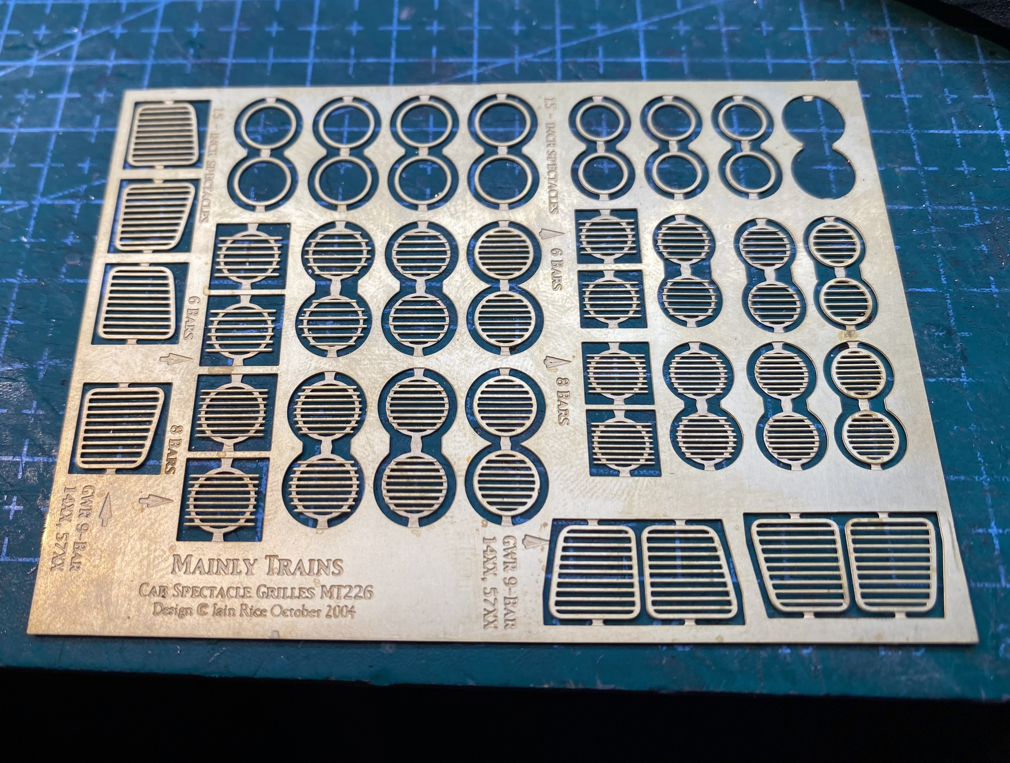
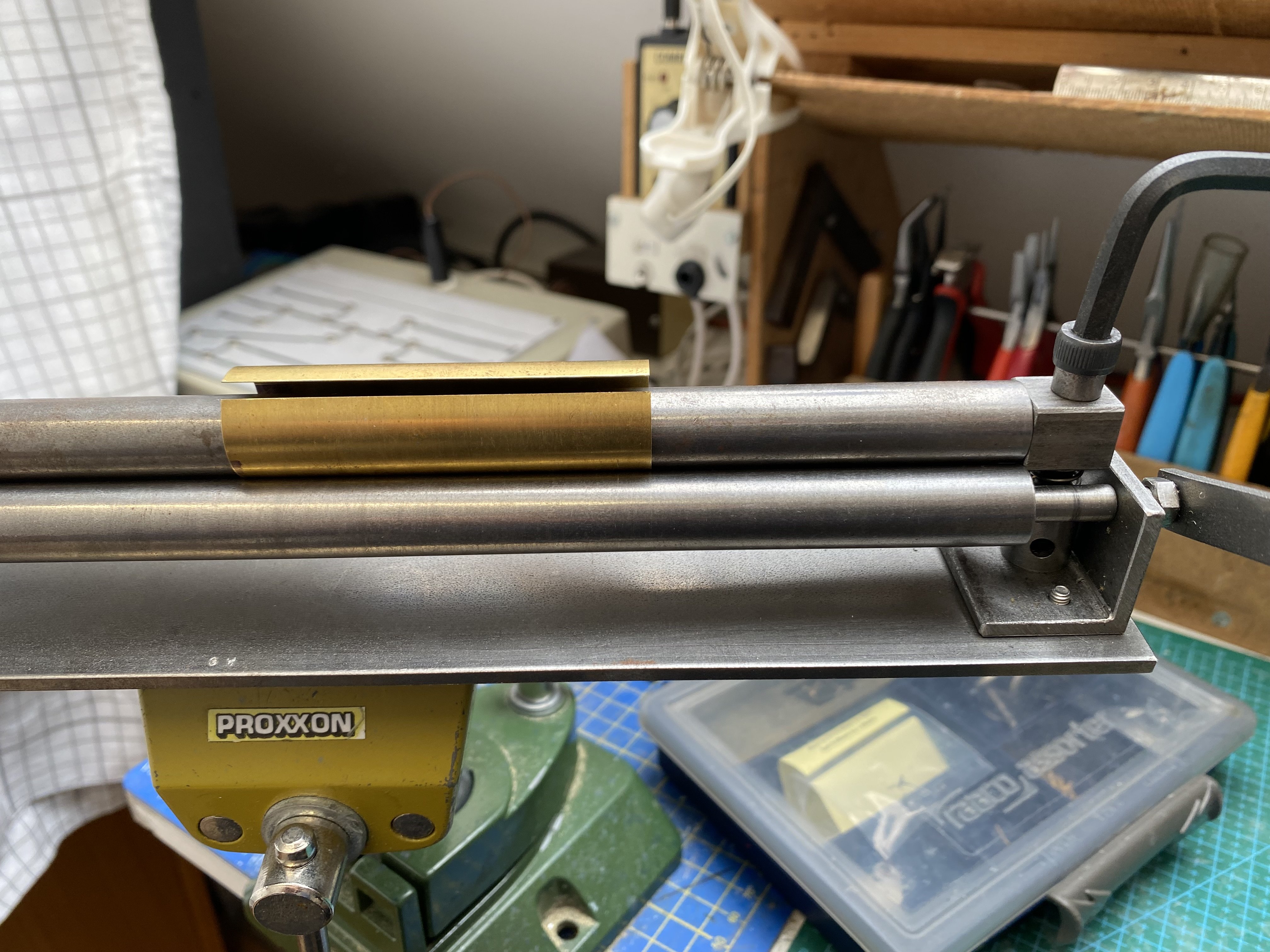
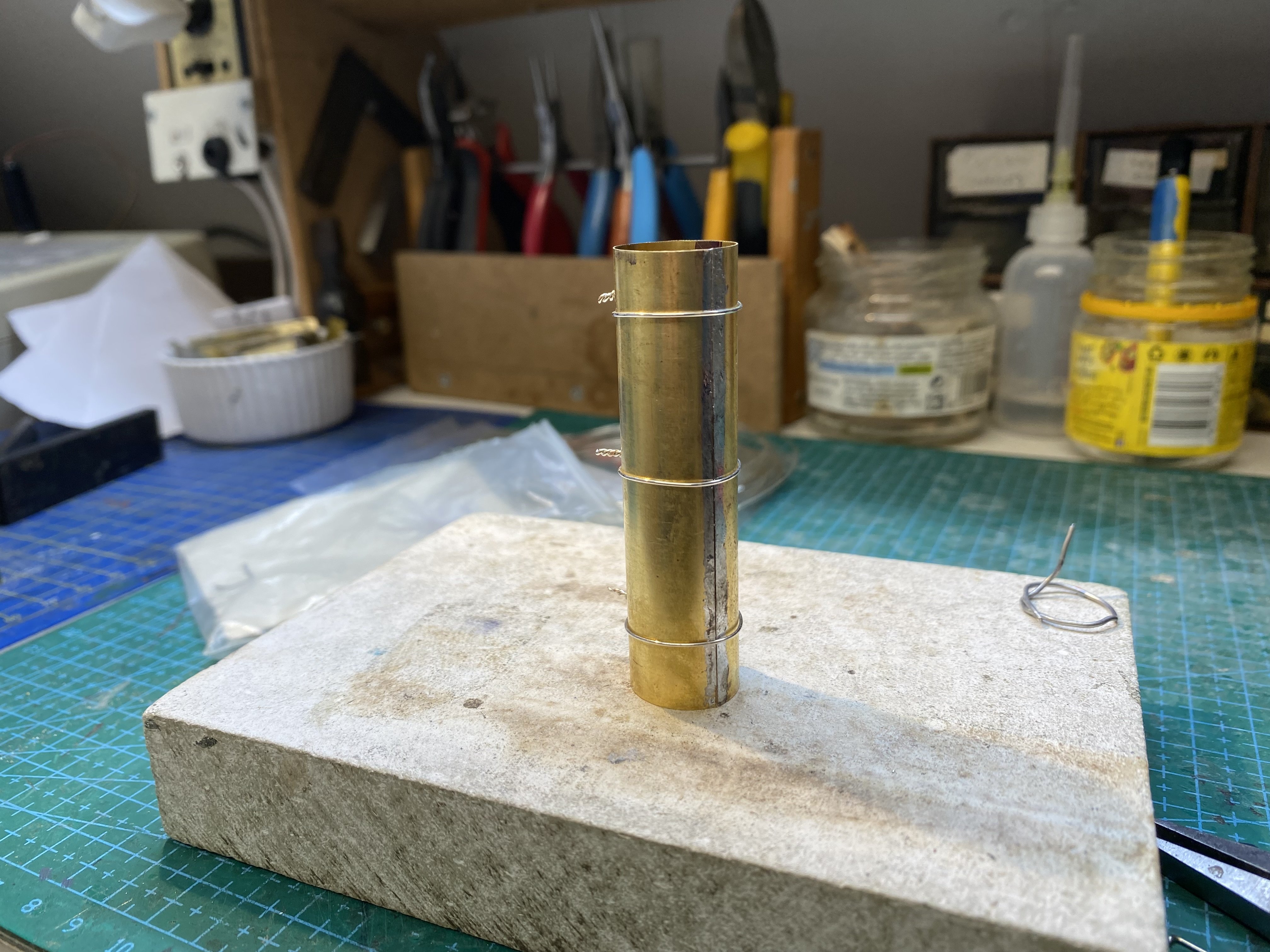
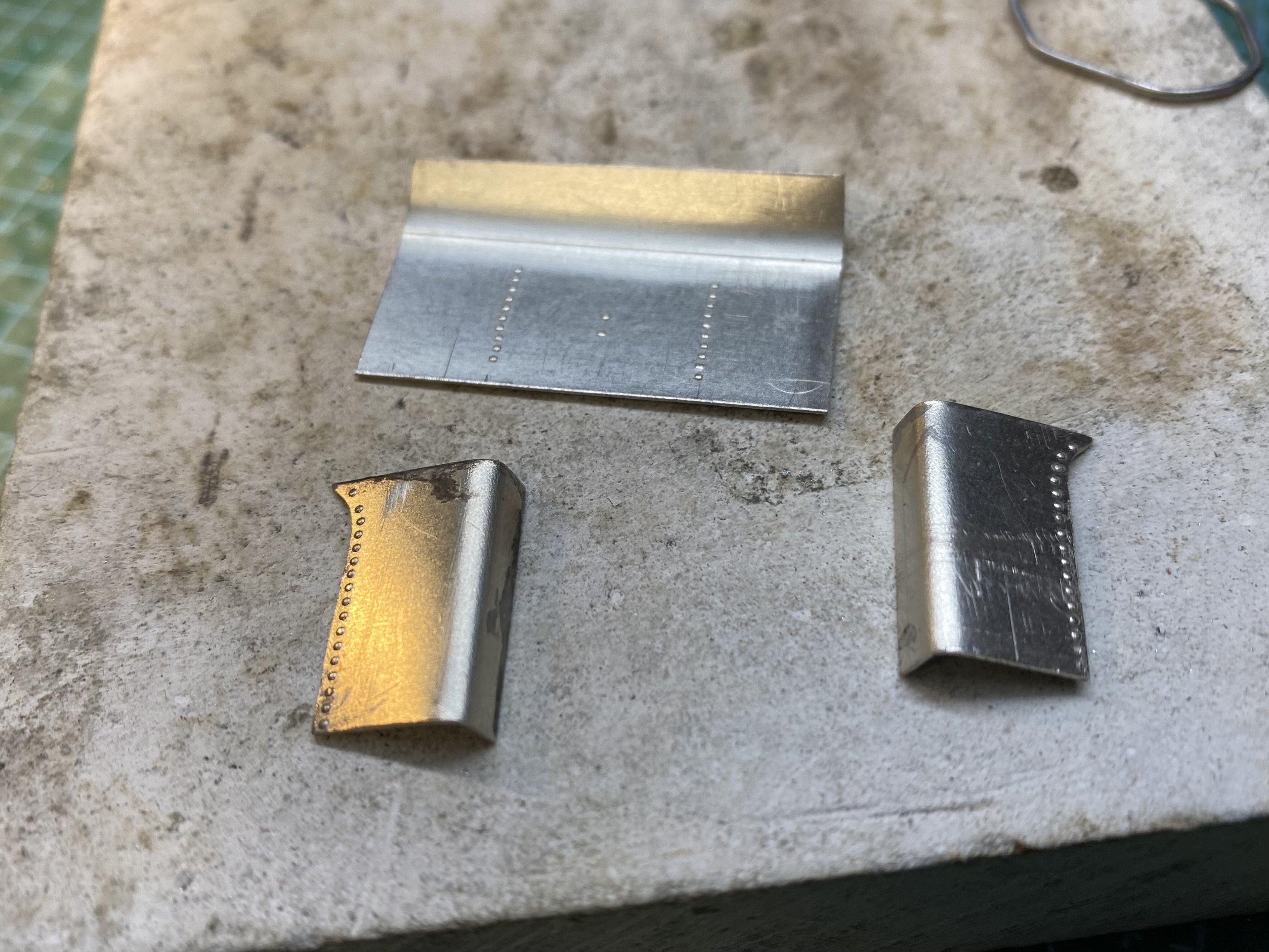
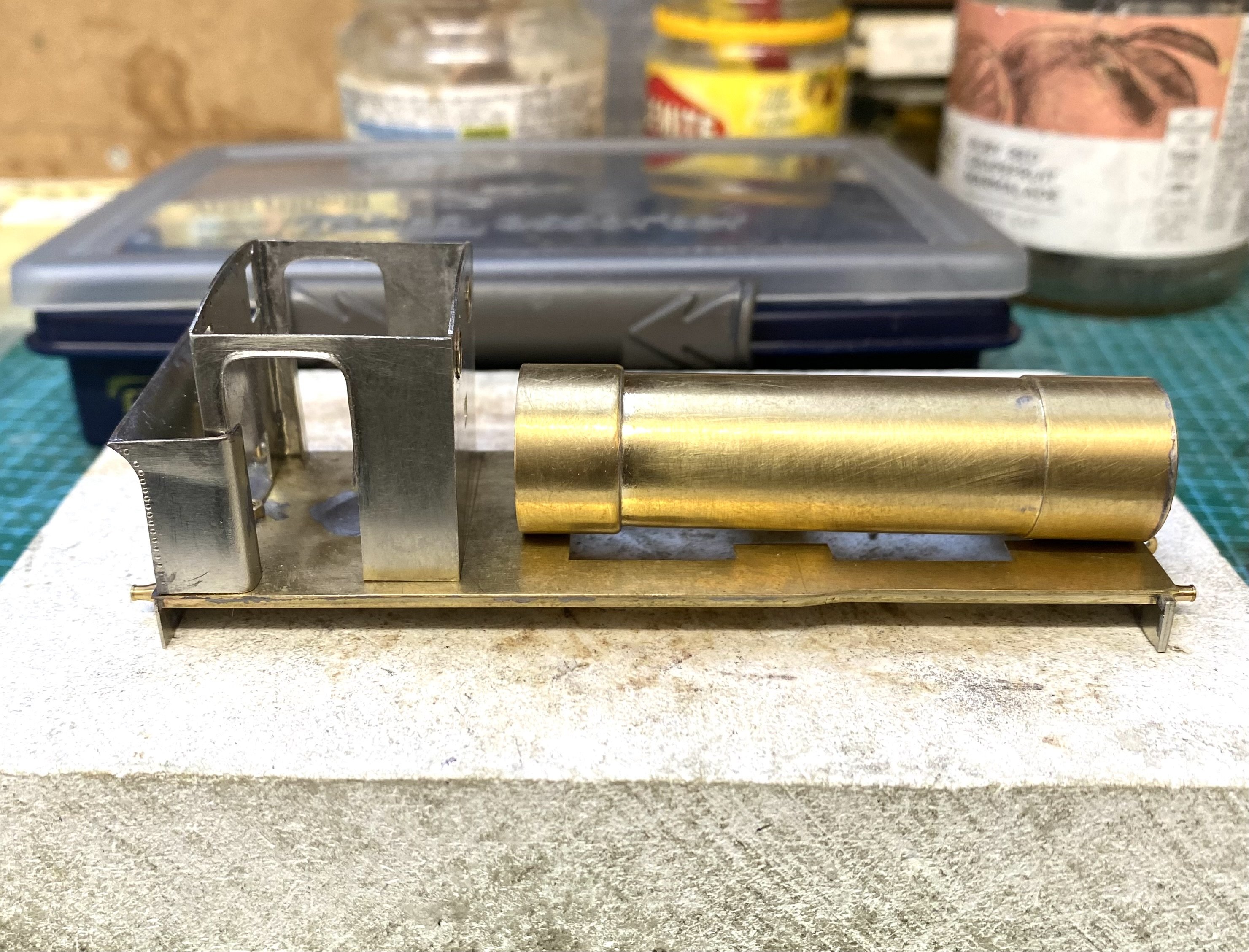
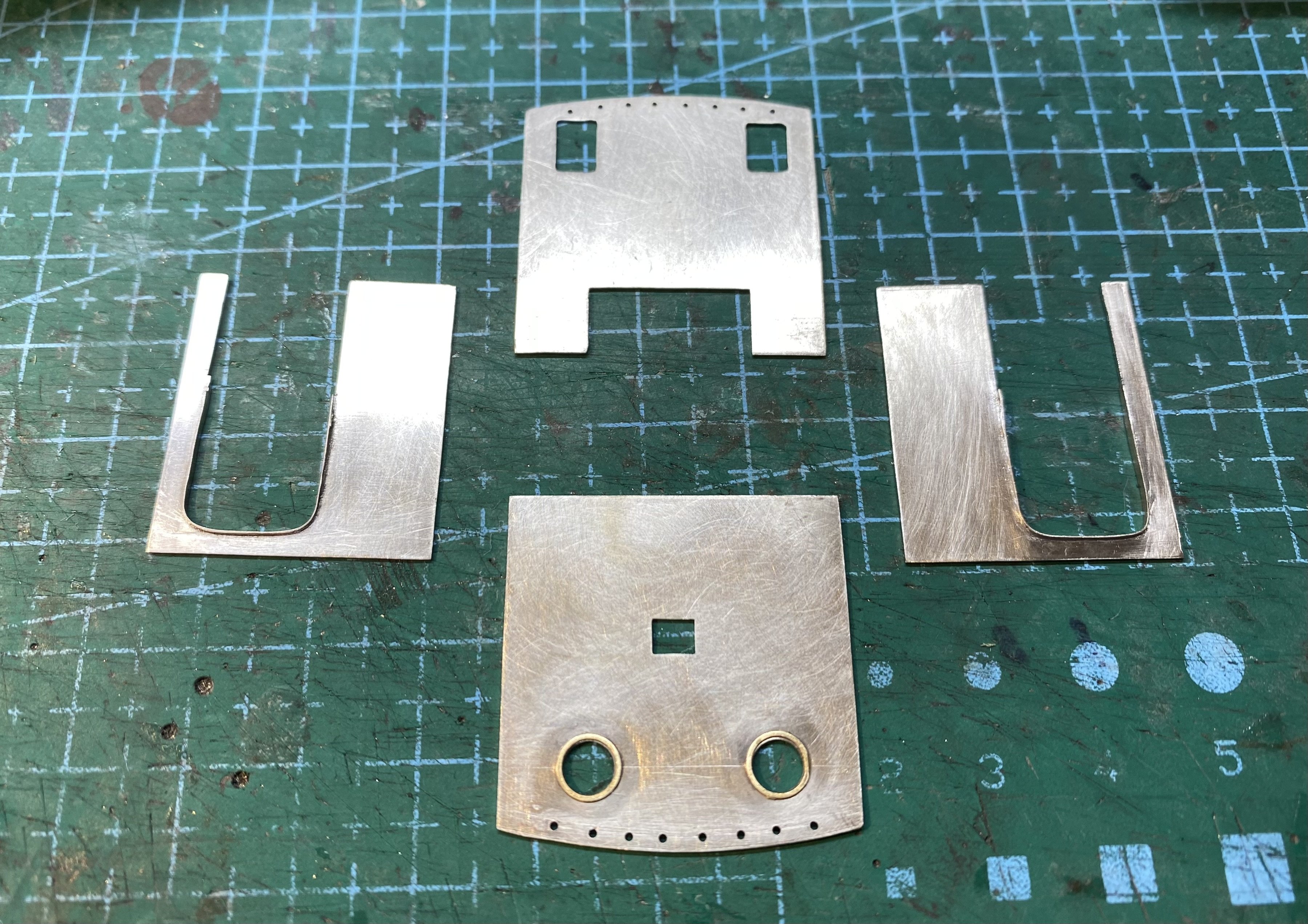
Moving forward again with No.9. First, a cab flatpack in 16 thou nickel silver. A jolly afternoon spent with piercing saw and files, listening to the rain on the roof window. The window surrounds on the cab front sheet came from this lovely Mainly Trains etch (MT226) designed by Iain Rice and available from Wizard Models. Bunker bits. More nickel silver and some embossed rivet detail. Boiler rolled from a rectangle of 10 thou brass... Firebox end has 3 additional layers with the front edge contoured. The smokebox will get another layer to incorporate the smokebox saddle. Given that this one will be driven on the front axle, I'll need to keep clearance for the gearbox. Haven't quite sorted this yet. Travelling hopefully Alan

- 886 replies
-
- 13
-

-

-
Windows can make or break a model building. Good ones really pull everything together. Those look great John. And I can see the sash frames!
-
I think it's worth paying a little extra for decent piercing saw blades. I've found that the cheaper ones are harder to control and the cut tends to drift sideways. I always buy Vallorbe blades now - grades 2, 4 and 6 - the bigger the number the finer the cut.
-
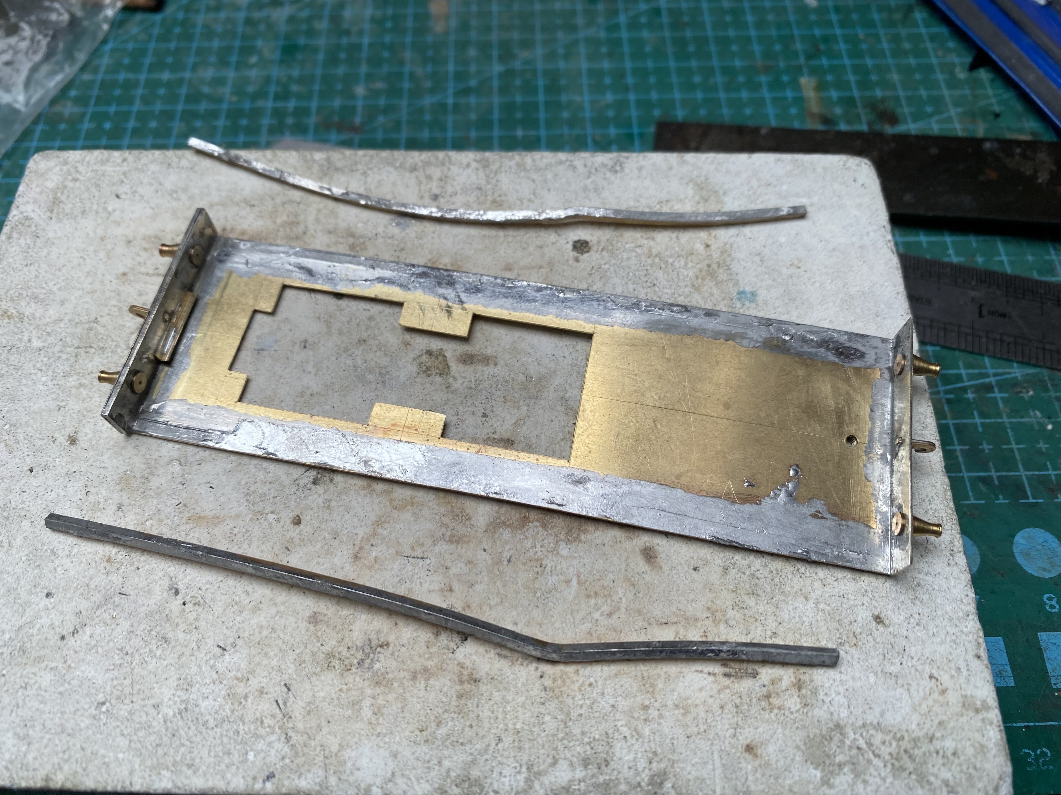
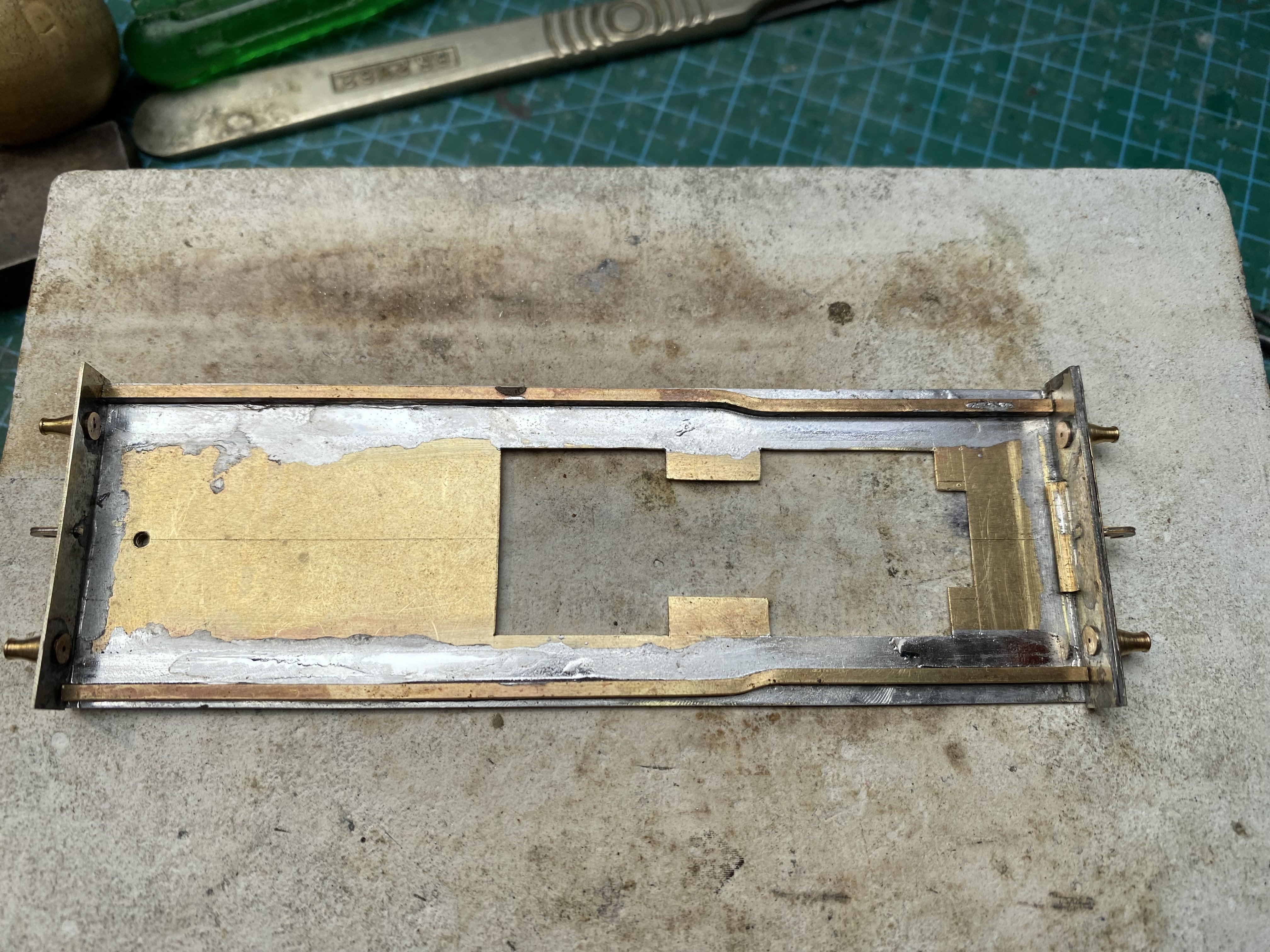
I could've left the running plate as it was - scratch building in 4mm is full of compromises, a track gauge of 16.5mm being not the least of those - but I knew it would bother me so, biting the bullet and ladling on the flux, the valances came off again. Not particularly neatly. New shaped valances made up and soldered in. Bending that 1.5mm square brass rod is no joke, even after annealing it. Running plate shaped to match and cleaned up. Shuffling forward quietly and pretending it never happened Alan
-
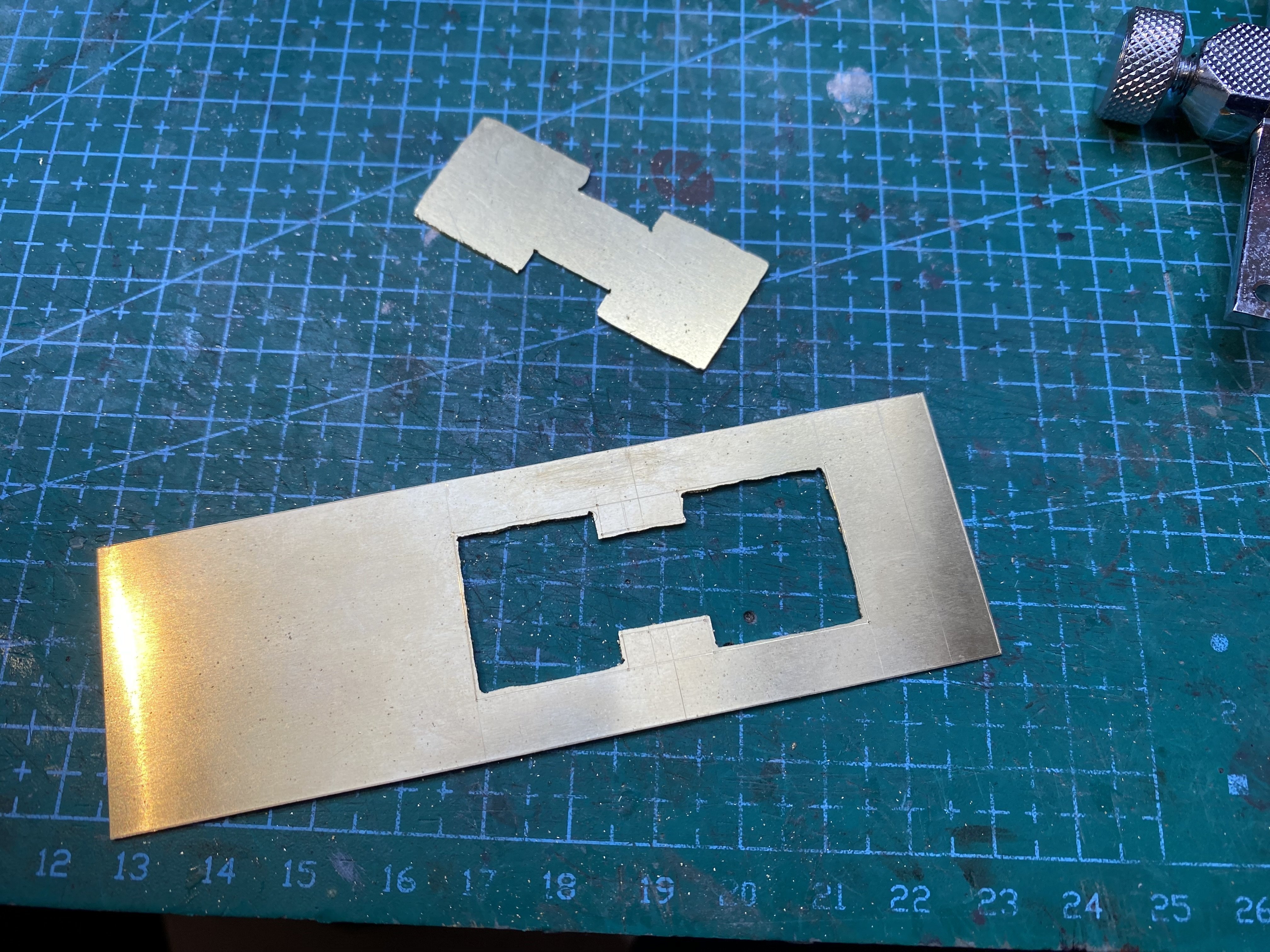
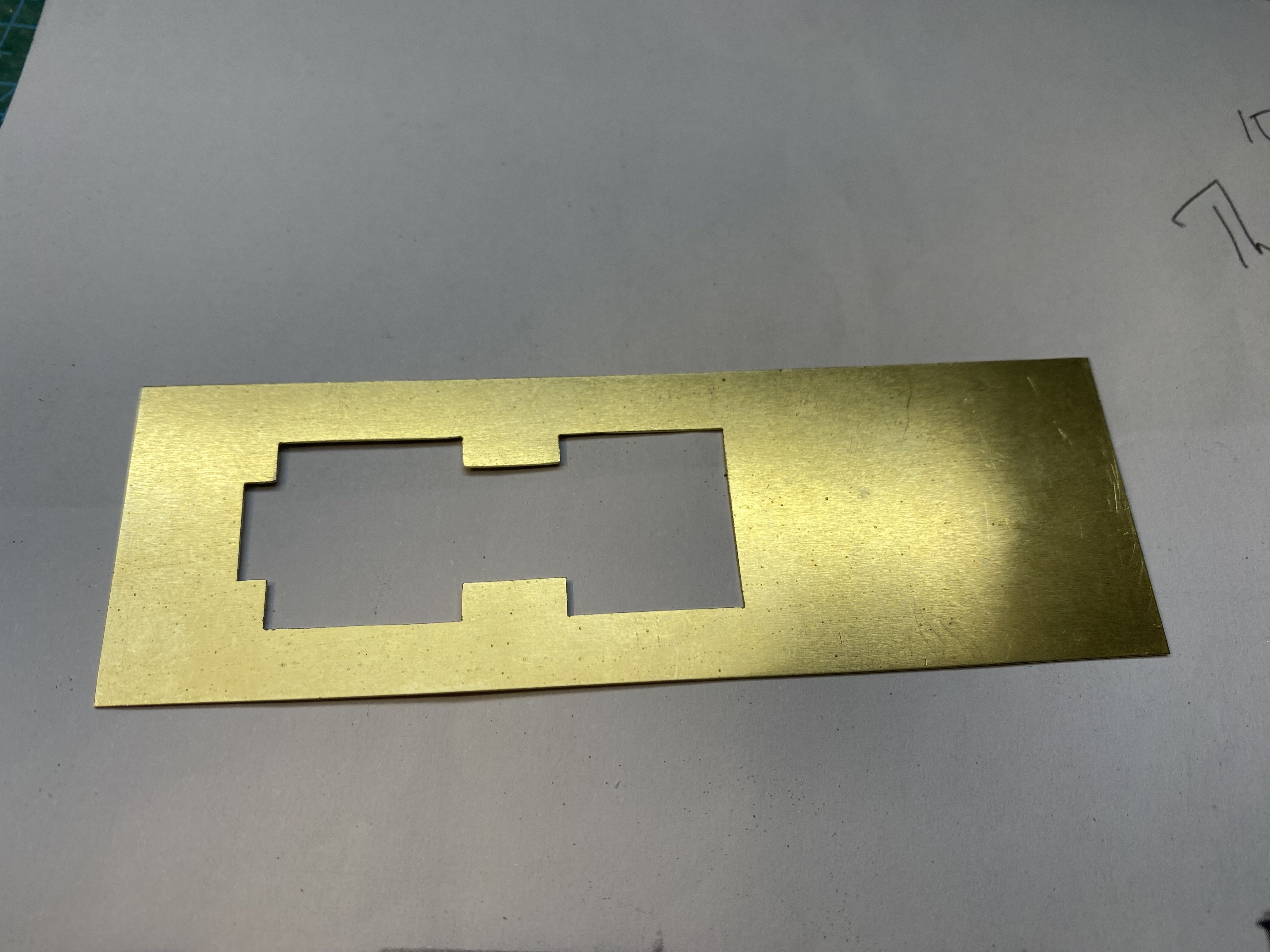
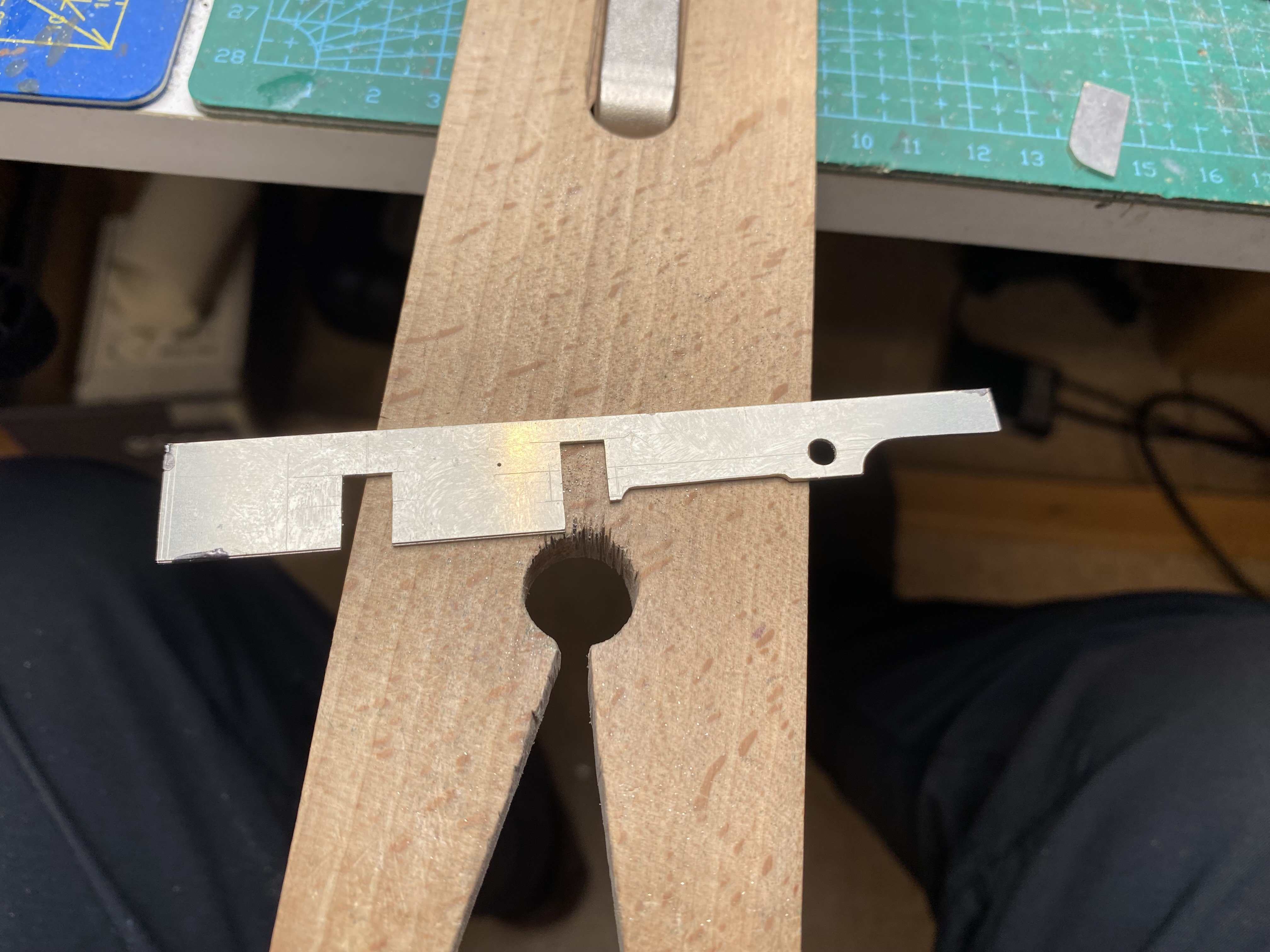
Ah John, I play safe. After scribing guide lines, I drill holes near each corner and cut inboard of the lines with the piercing saw. No need to be too precise (first photo). Then I file up to the lines using needle files (second photo).
-
Spoke too soon! Looking again at the Casserley photo in Leslie's post above, the running plate narrows ahead of the tanks. Bu**er.
-
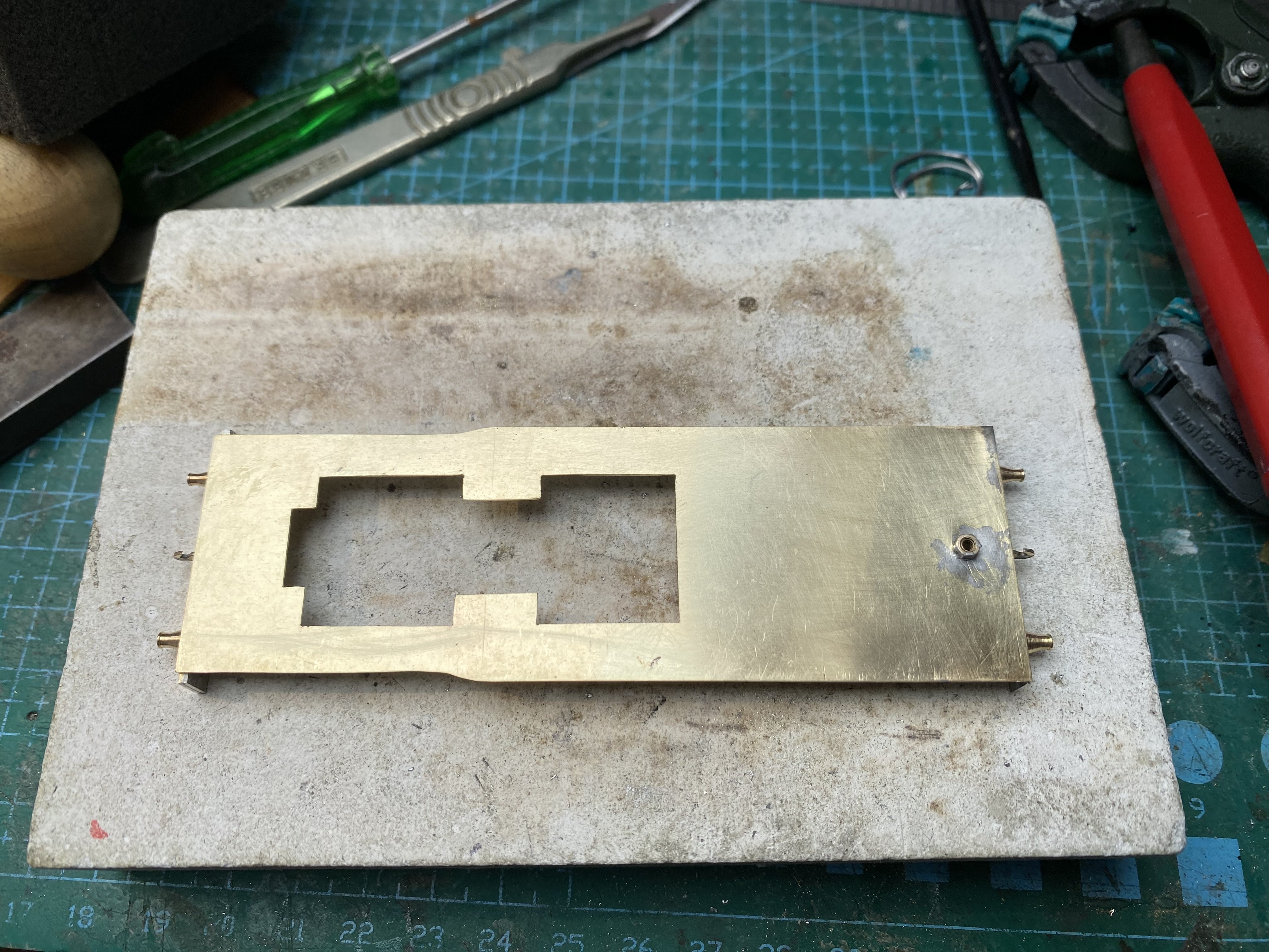
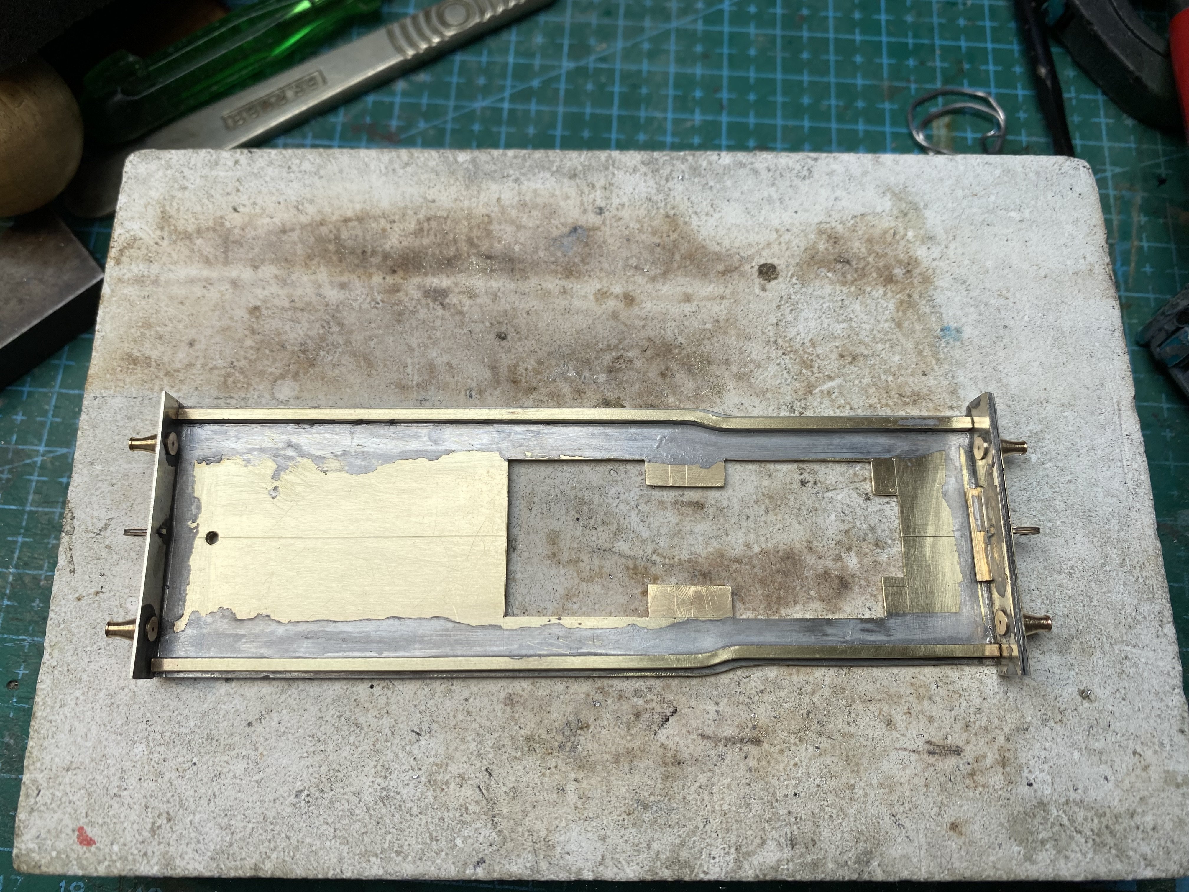
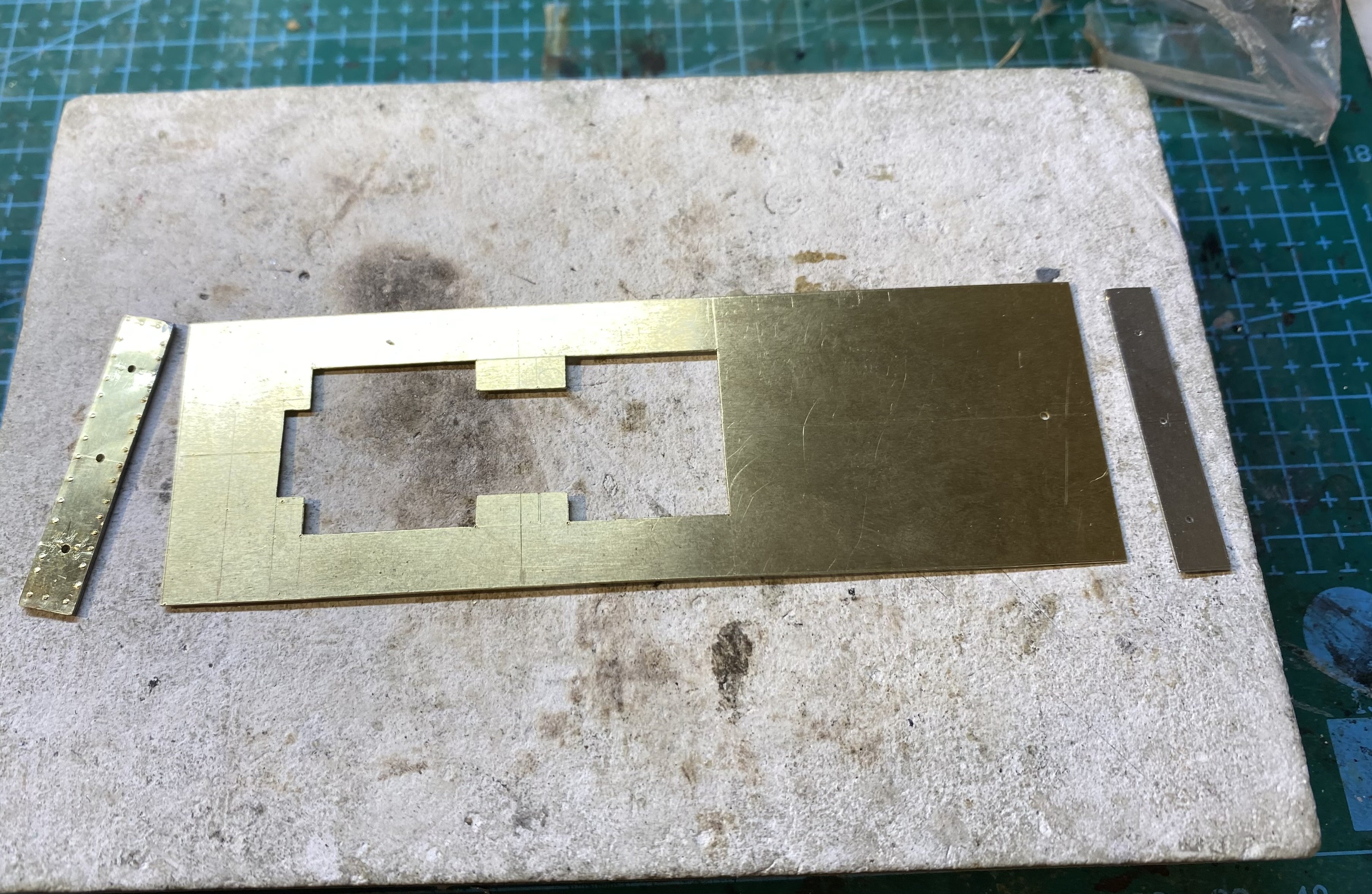
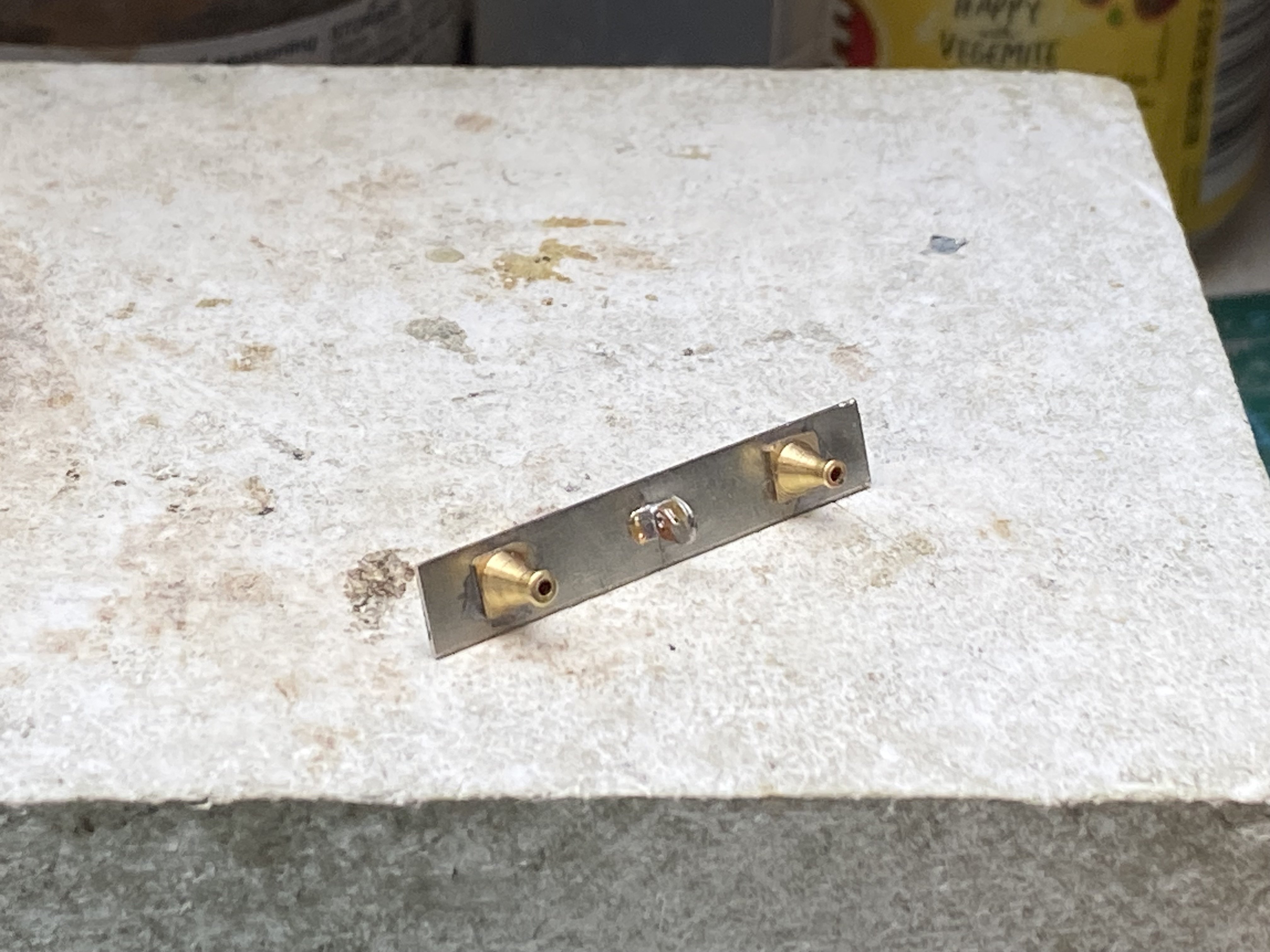
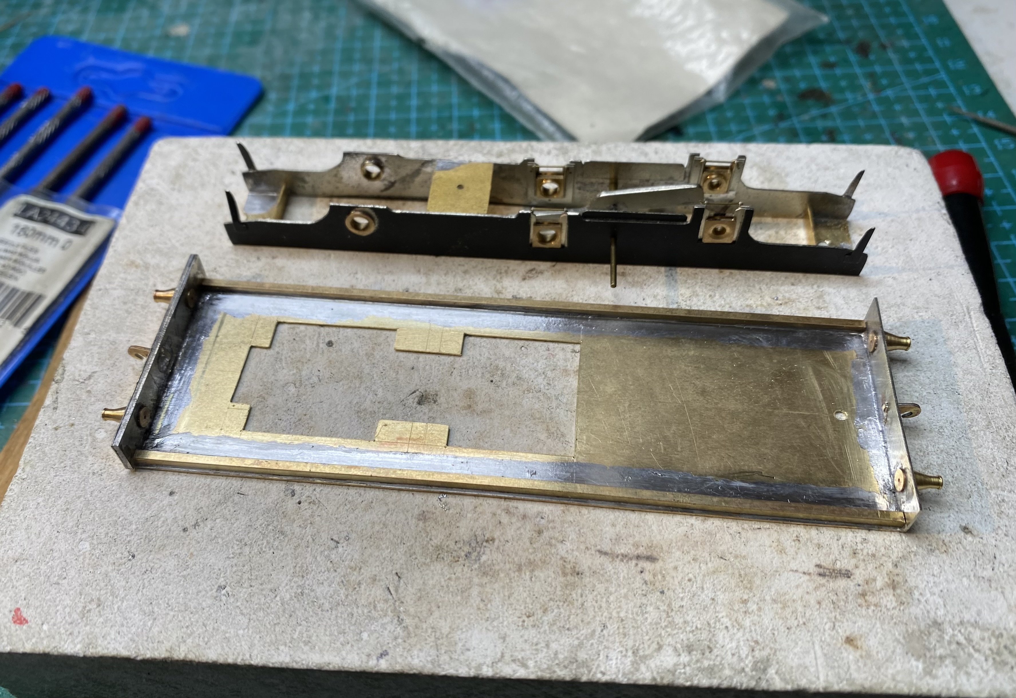
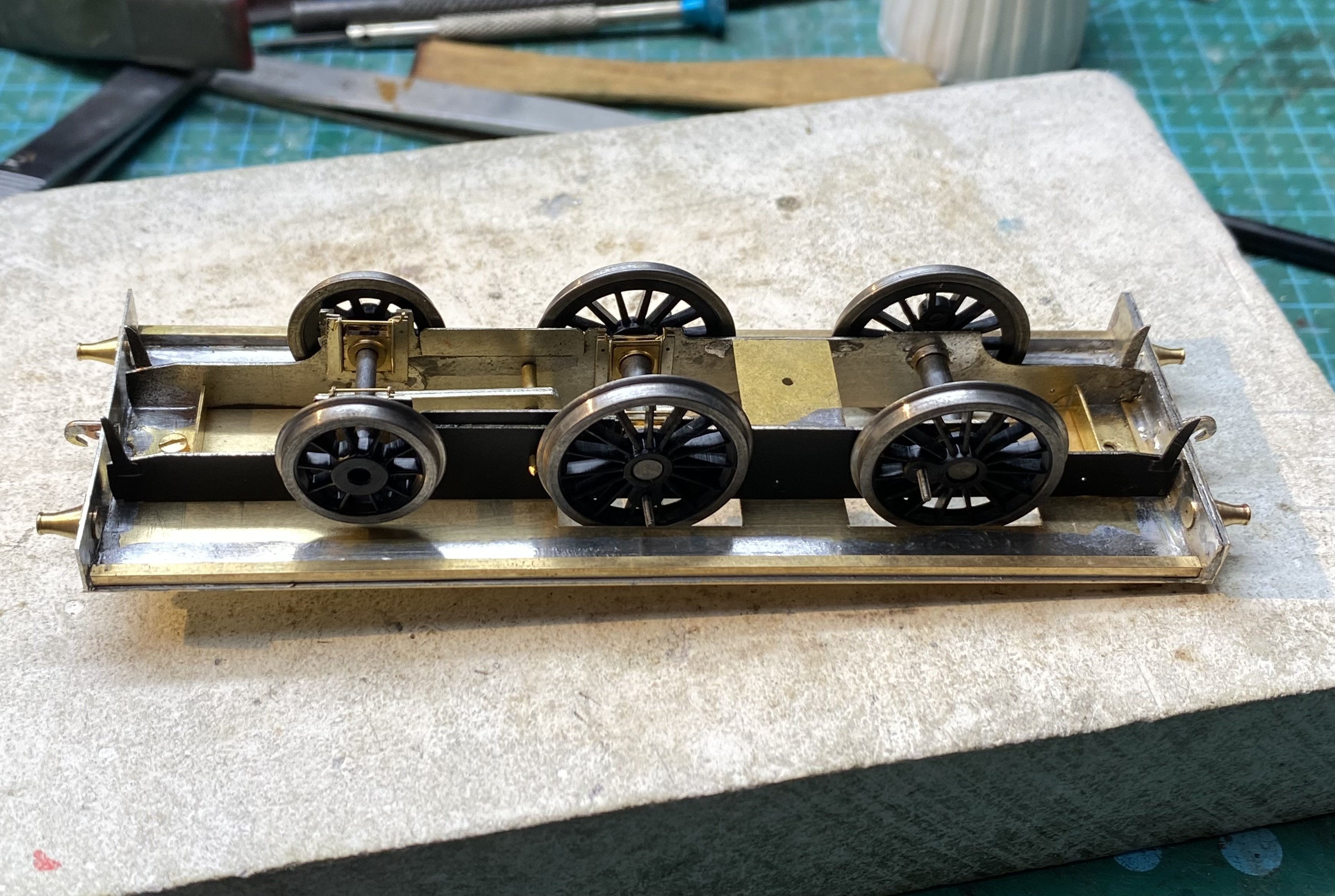
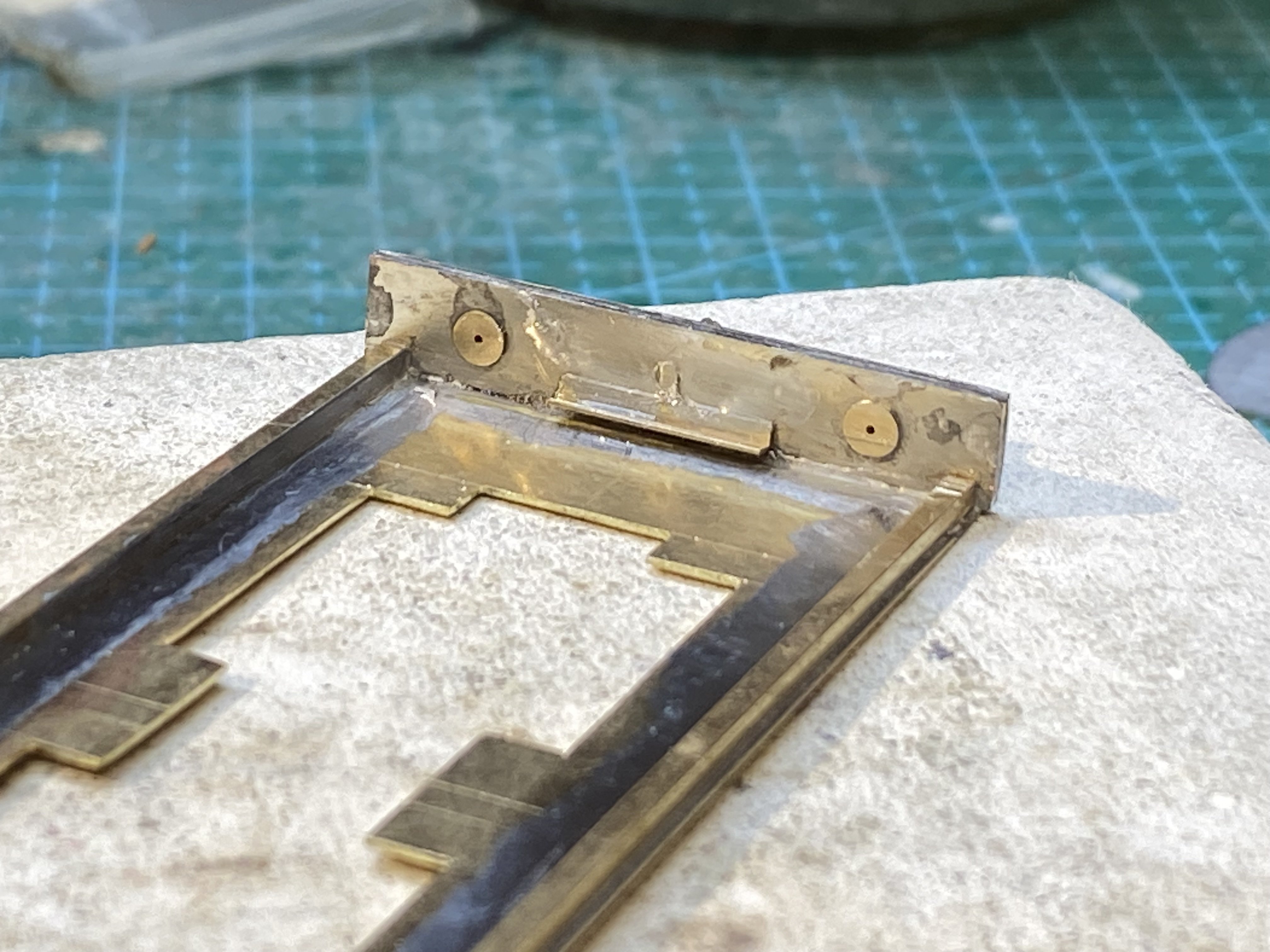
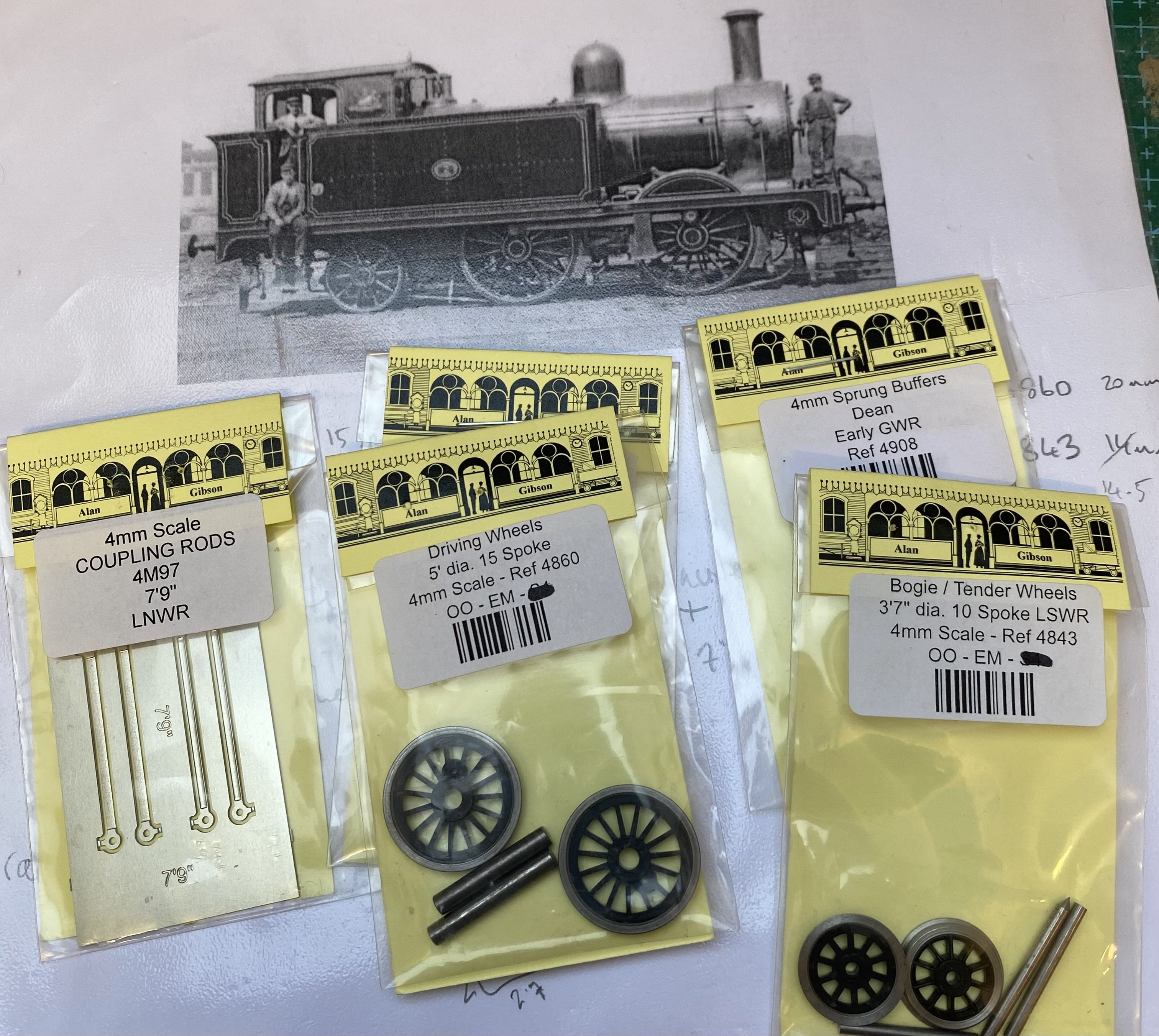
While waiting for replacement wheels, I've made a start on No 9's running plate in 16 thou (0.4mm) brass. Buffer beams are 2 layers of 16 thou nickel silver plus an extra 5 thou brass layer on the front one - photos of the prototype suggest it might be made of wood with a metal facing. Buffer shanks are from Alan Gibson (4908, Early GWR, Dean). Reggie the Soldering Unit made a neat job of soldering these on. 1.5mm square brass rod for the valances stiffens the whole thing nicely and gives it some much needed strength. The front chassis spacer slides under a little bit of 1.5mm brass angle the same width soldered to the back of the buffer beam. This secures the chassis and keeps it centred. At the back there's a 10BA bolt into a captive nut on the running plate. No disasters today. Alan
-
Yes Killian, I found that photo in Des Coakham’s book where it’s identified as No 2. It’s a useful image for gauging dimensions and proportions along with his info on wheel sizes which helped me to scale the photo. There seems to have been five built altogether, numbered 2, 9, 10, 13 and 16. All started as tender engines and all were converted to tanks around 1900.
-
Ok, where do you surrender?
-
Many thanks for posting this photo Leslie. I can see details here that I missed in the other pics I've seen. Very useful. Please convey my kindest regards to The Syndicate's lawyers and assure them that I will treat said image as visual reference material only and will observe the laws of the land at all times
-
I'm with you David. I'm continually impressed by what people are doing with 3D printing, and the element of repeatability has to be a major advantage but every time I consider attempting it myself, the task looks less like a learning curve and more like a vertical cliff face and I speak as someone who wrote educational software for children with learning difficulties back in the day. OK, back in the last century. Things have moved on a long way since the days of BBC Basic and such skills as I had then have long since evaporated and wouldn't be applicable now in any case. So many projects, so little time, so no time available to learn new stuff! So I retreat and stick with what I know. Probably it's just old dogs/new tricks syndrome.
-
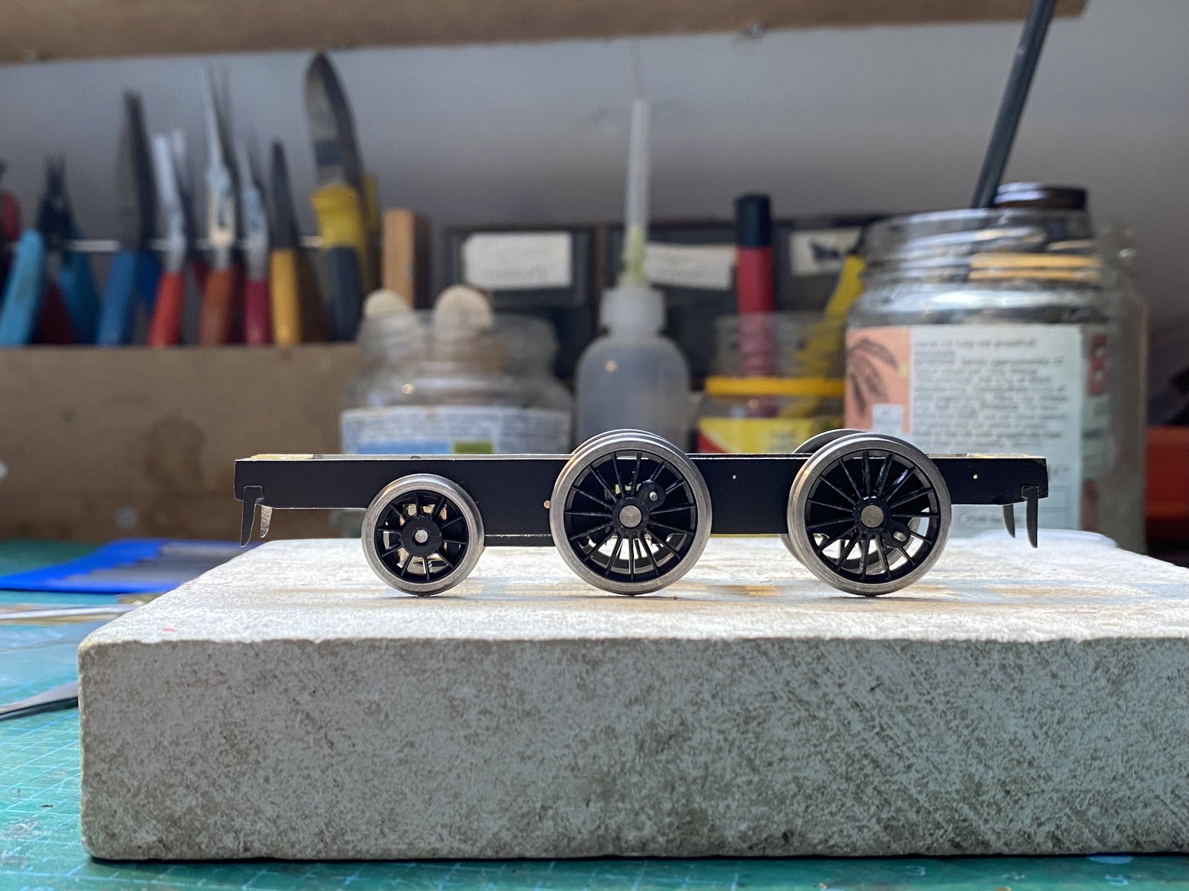
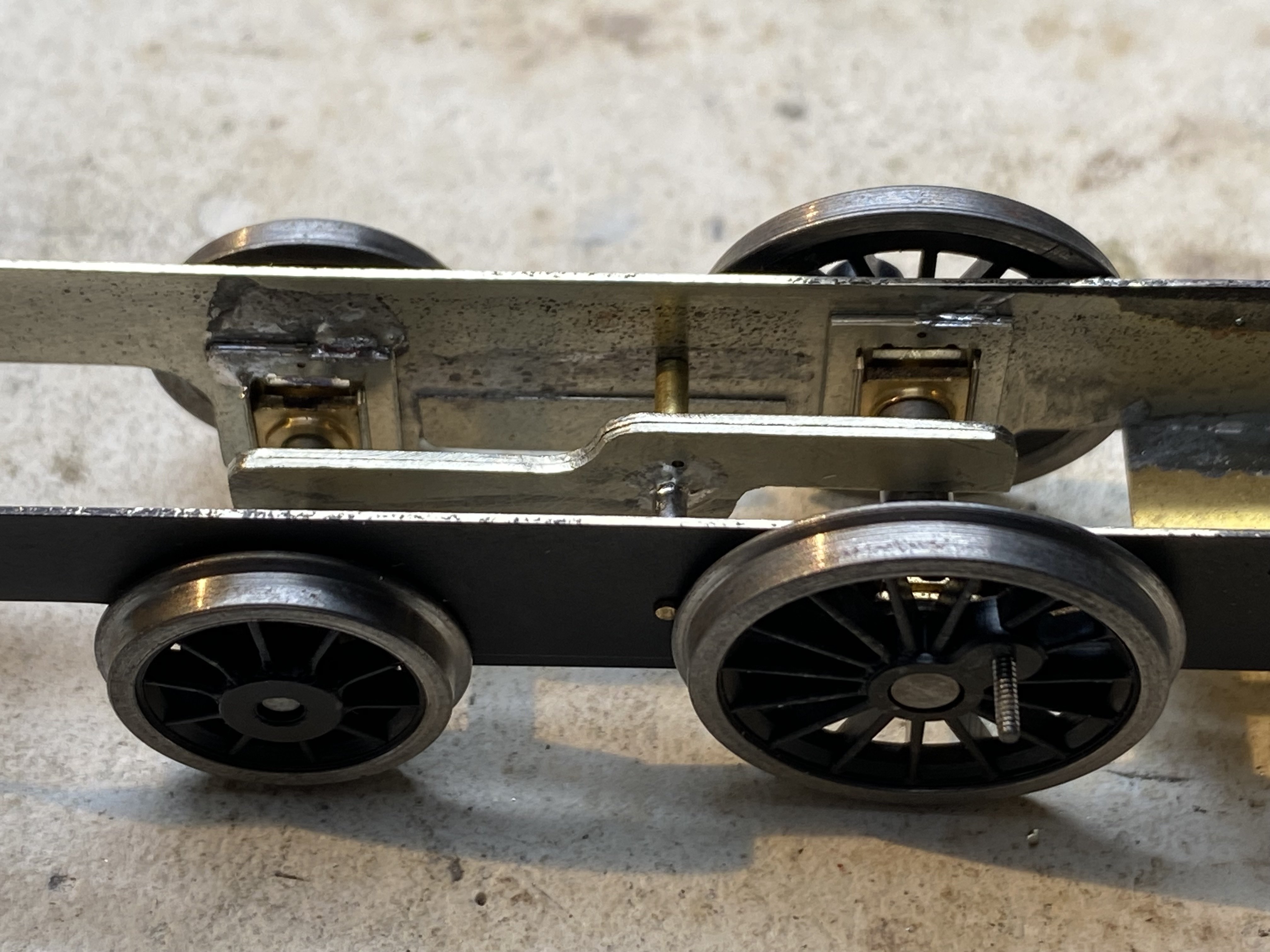
Wheels for No9 prepared and crankpins fitted without drama but then the inevitable pratfall. Gibson wheels are sometimes a very tight fit on the axles and need reamed a smidgeon. However.... The cack-handed fitter charged with the job reamed them a smidgeon and a bit with the result that they were too loose on the axles to be reliably straight or secure even with Locktite or its equivalent. Idiot! He was docked a day's pay and sent to bed without any supper. New wheels ordered. However it did allow wheels to be temporarily slipped onto the axles to check the compensation beam before it was permanently fixed in place. Beam in place.. and it all sits level. Yay! Lesson for the day - Don't listen to podcasts while trying to do delicate stuff. I blame Dominic Sandbrook and Tom Holland. Alan
-
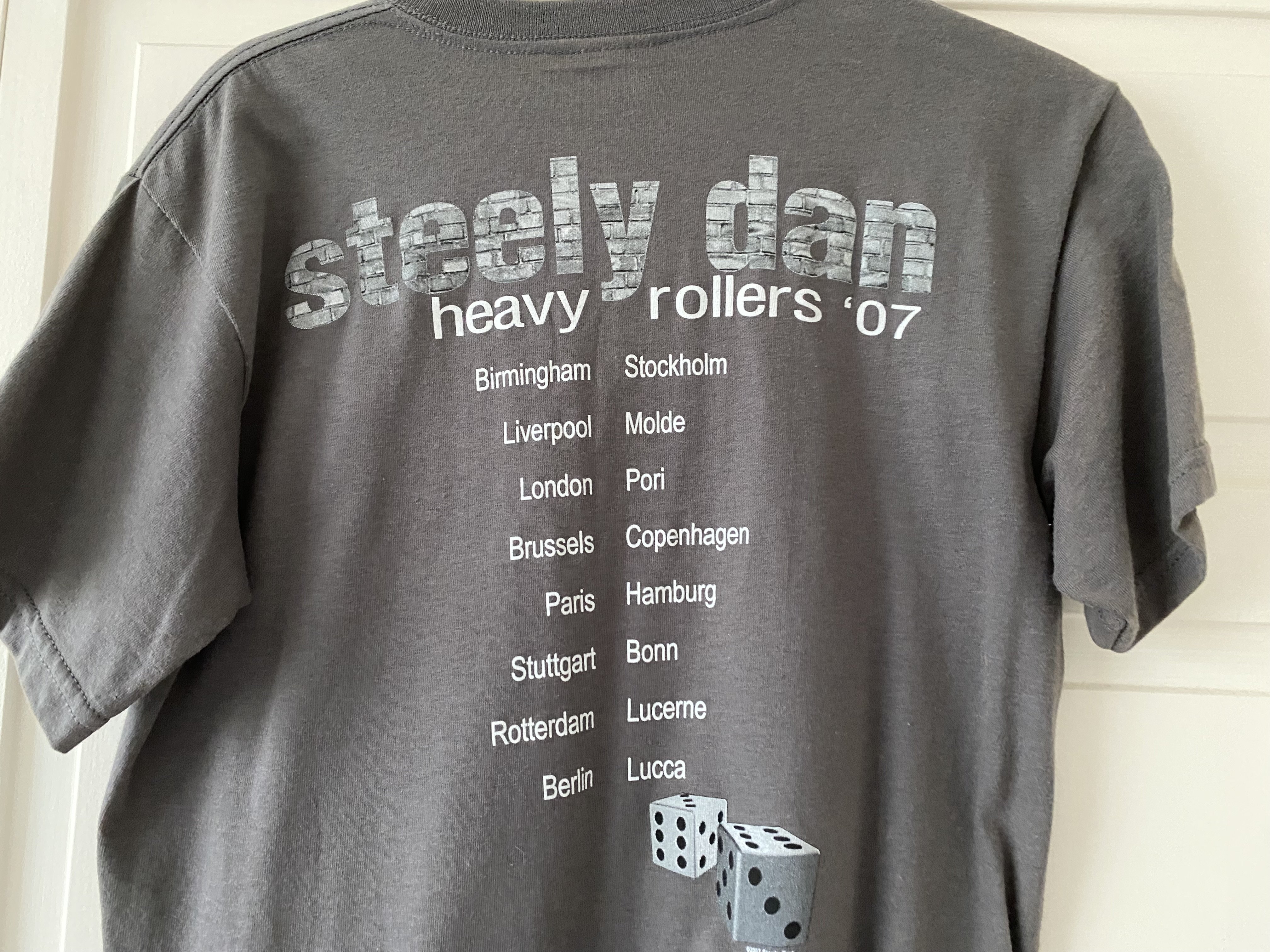
I managed to see them in Birmingham in 2007 - maybe you were there too - when Walter Becker was still with us. Brilliant night. I still have the t-shirt Back in the days before the internet and immediate gratification, I heard "Do It Again" on the radio and was bowled over. However the DJ didn't say who it was and it was 6 months before I heard it again and found out who the band were. The rest as they say in history, many hours of pleasure and a fine set of vinyl discs from which I will not be parted except at gunpoint.
-
"Little Green is one of my favourite Joni Mitchell songs - and perhaps a better name for a layout than Free Man in Paris. Or Led Zeppeiln's Kashmir, Steely Dan's Pretzel Logic" Reelin' in the Years? Change of the Guard? Sorry, I'll get my coat Little Green - Perfect choice. And a lovely song.
-
Looking magnificent. Best of luck for the show David. I'll cross my fingers here too.
-
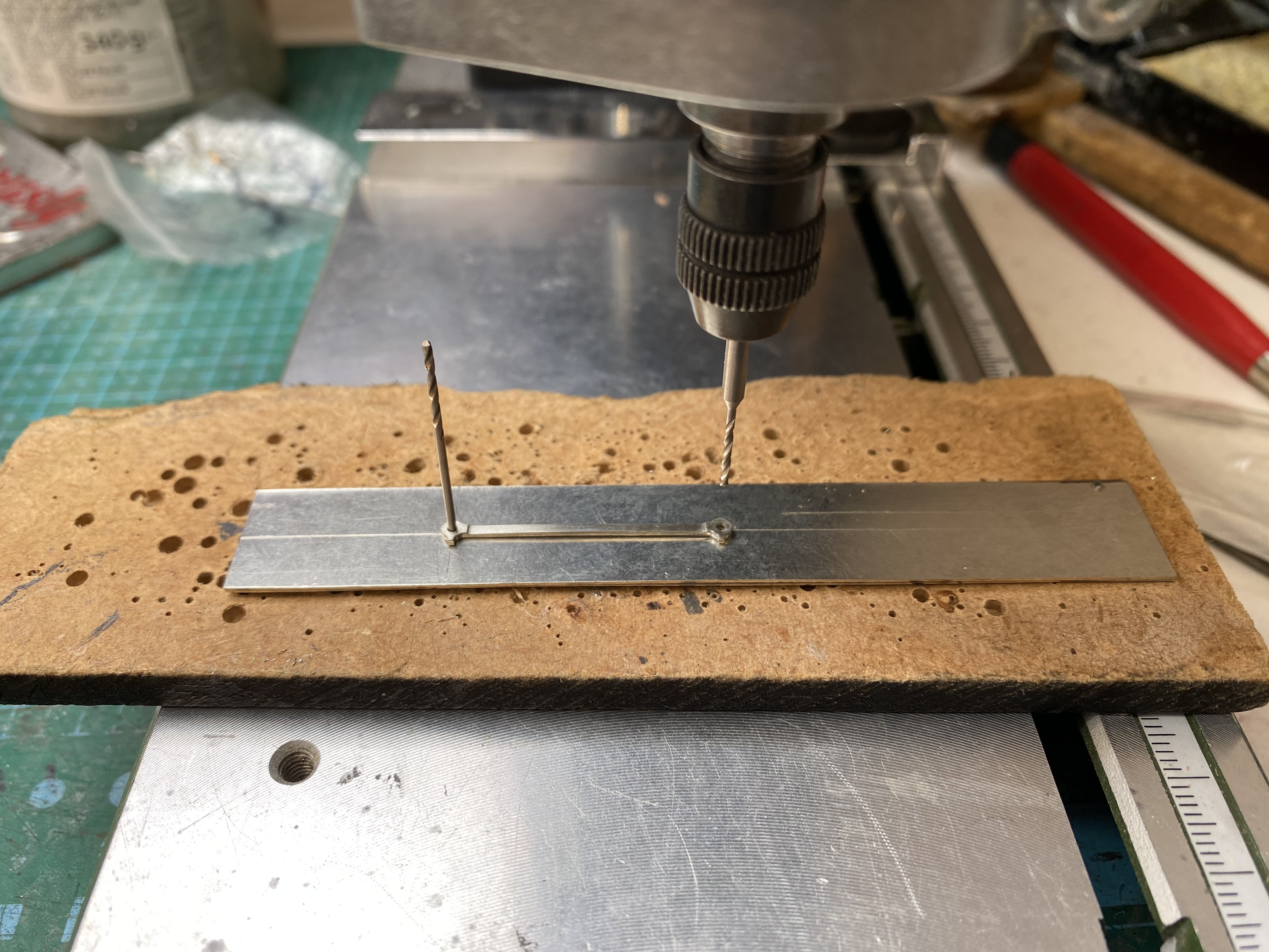
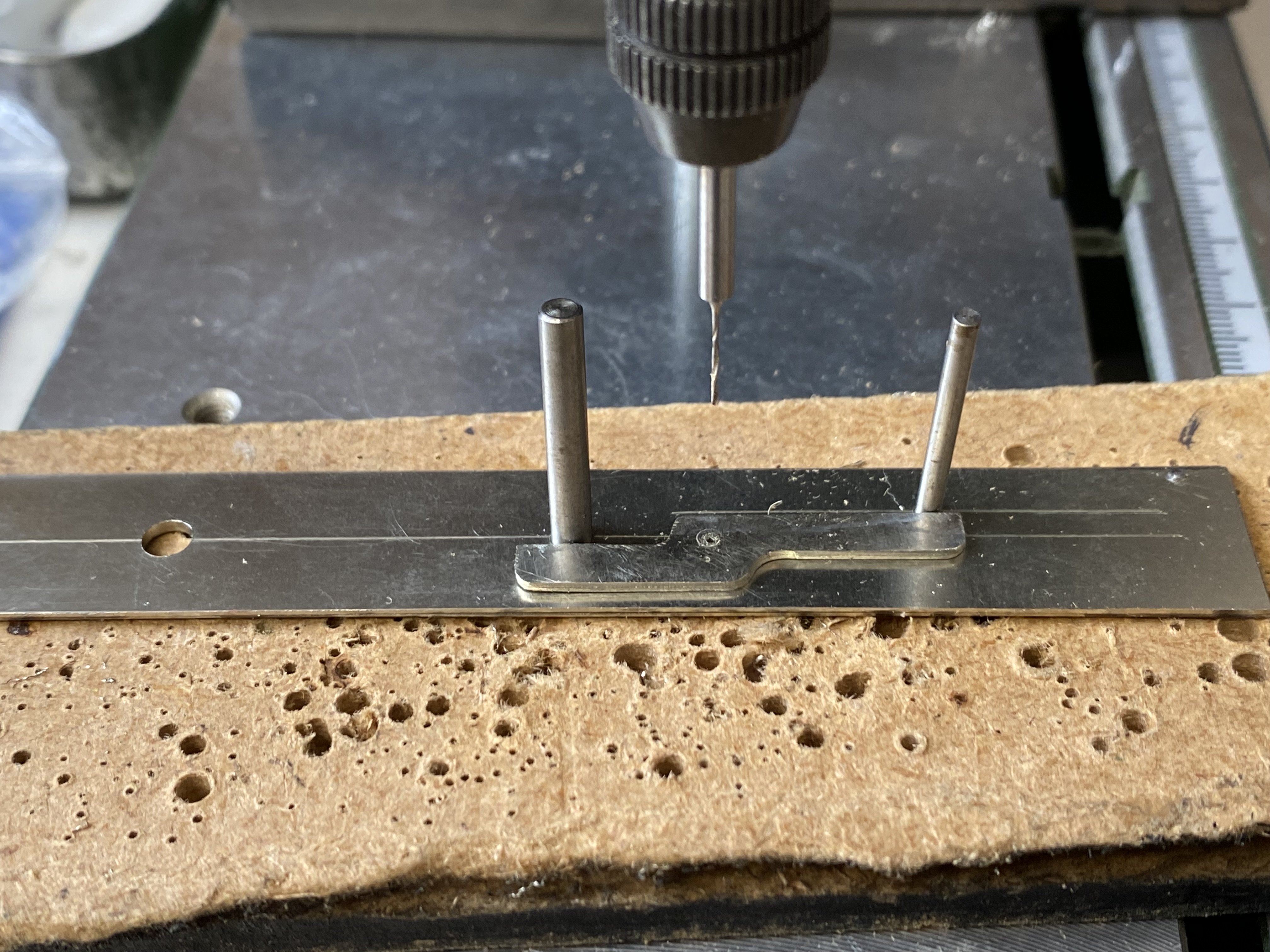
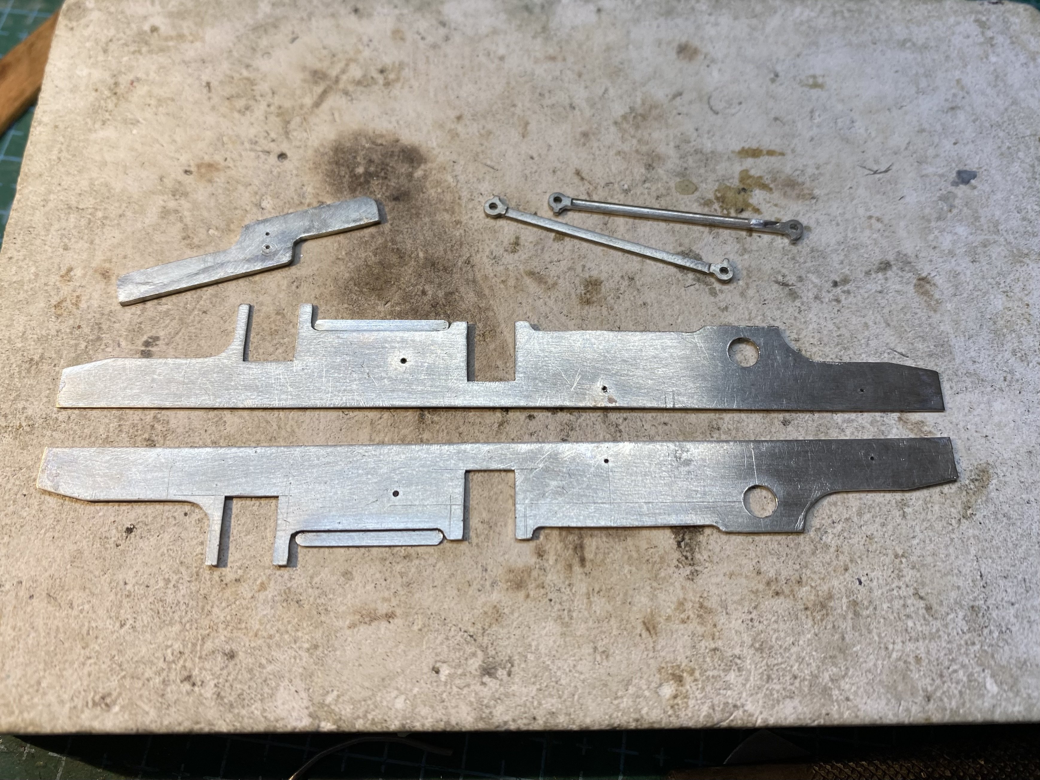
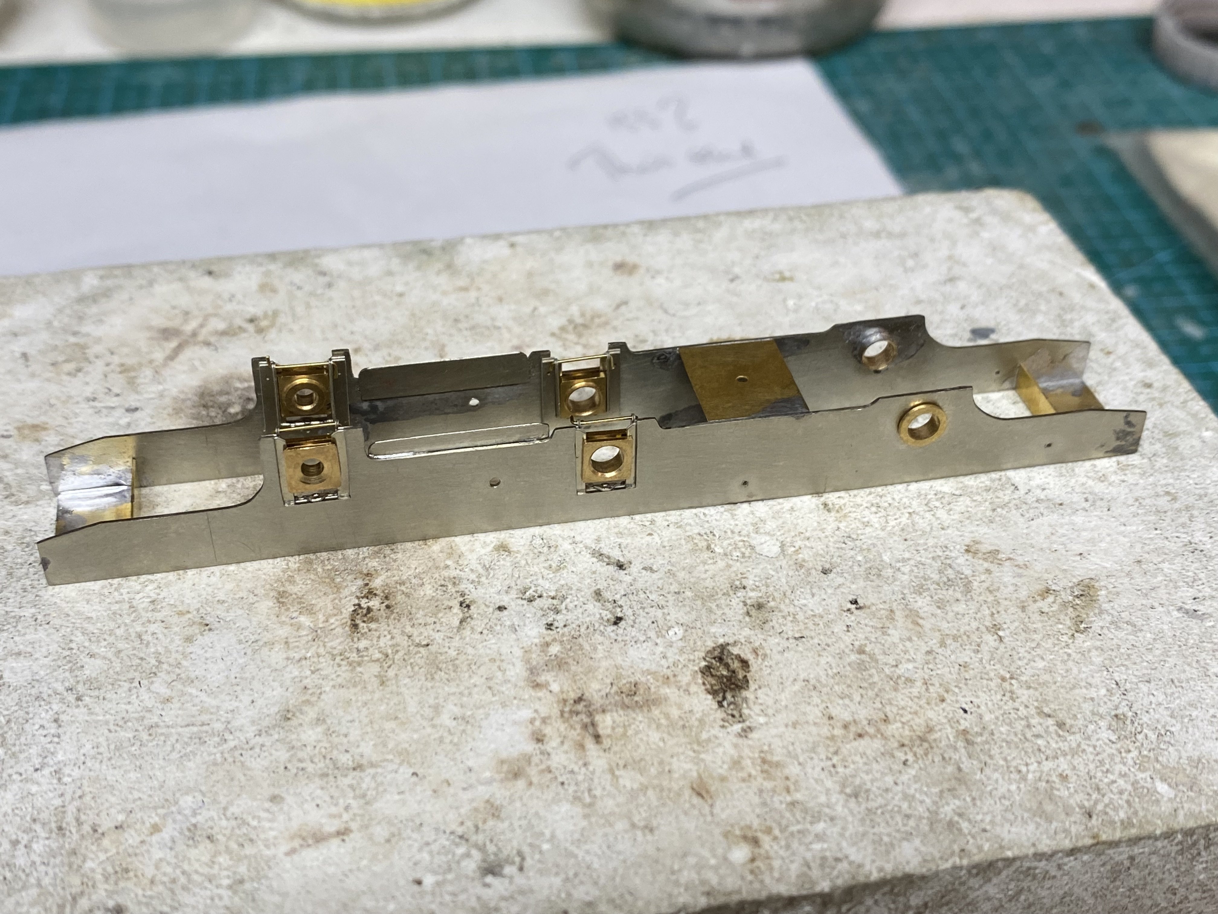
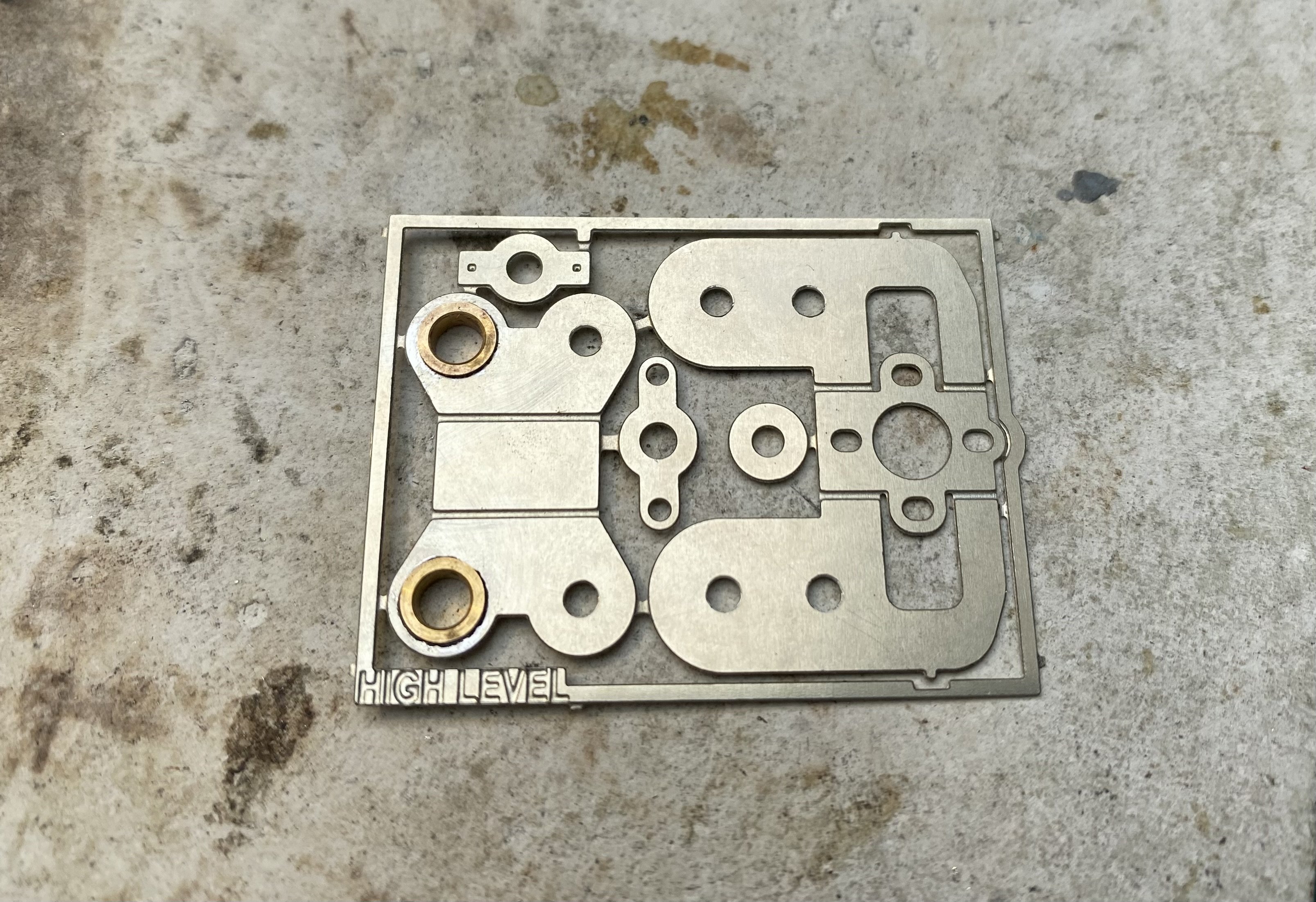
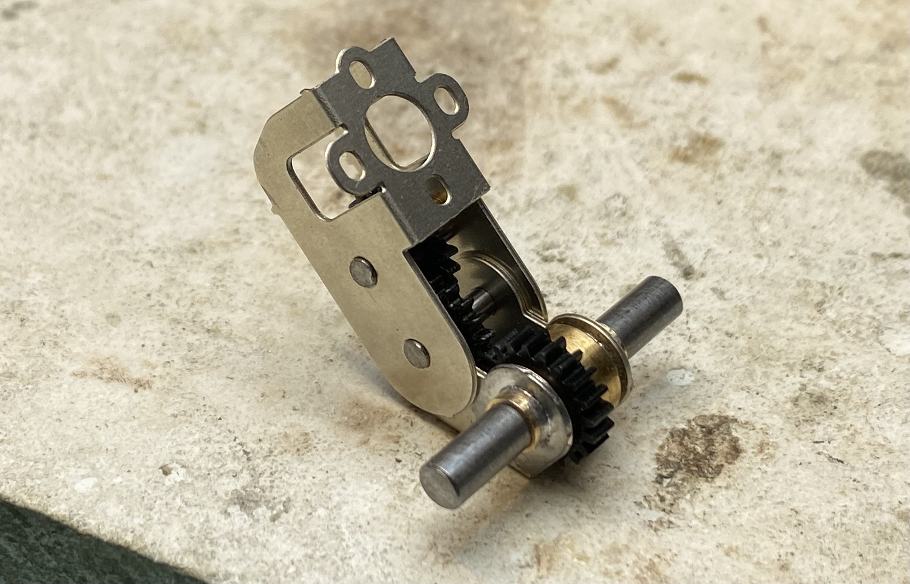
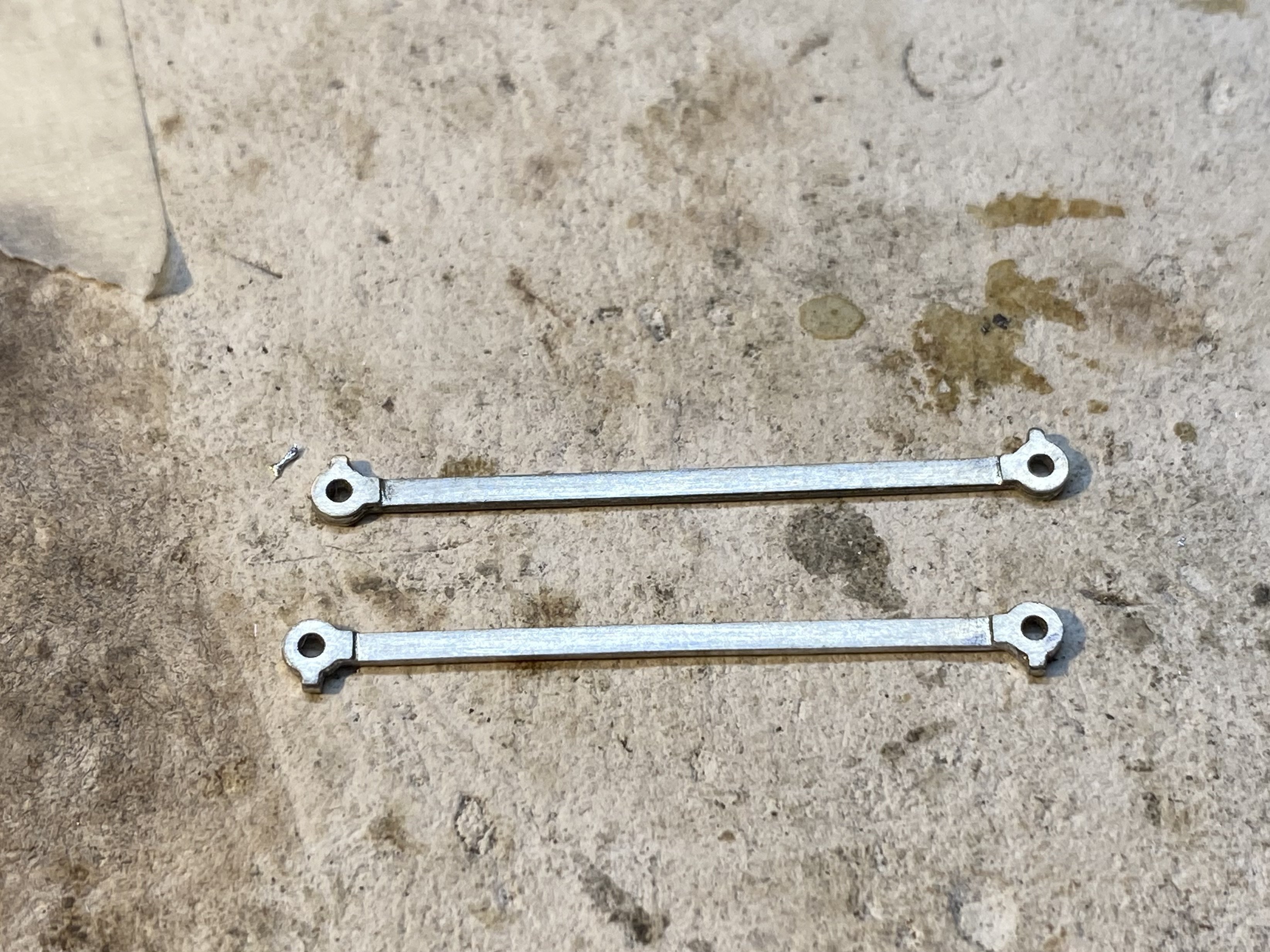
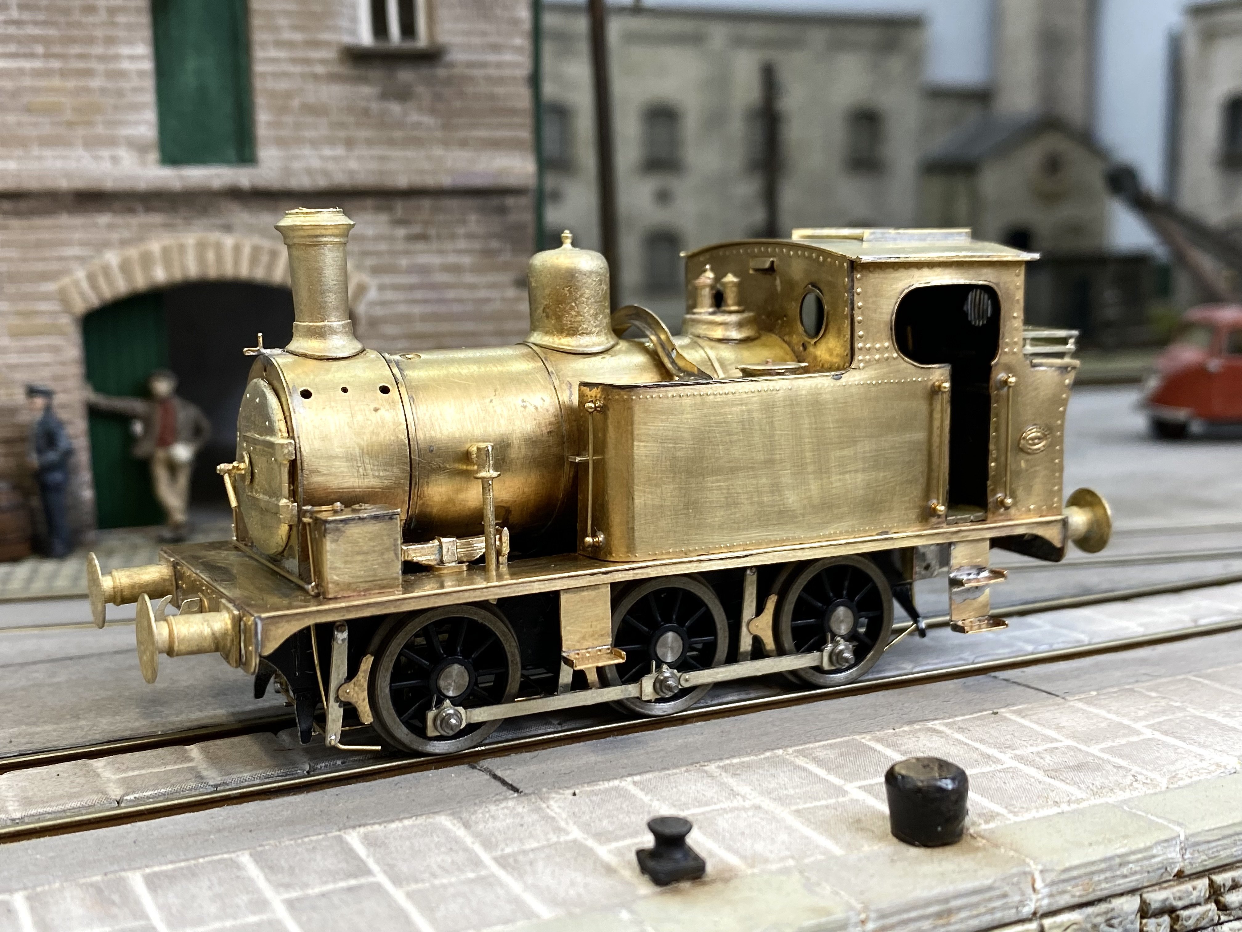
I already have more BCDR locomotives than can fit on the traverser at Kilmore but that's no reason not to build another one This is old Number 9, built by Sharp, Stewart as a tender engine in 1887, rebuilt as a tank engine in 1900. It survived into UTA ownership. Coupling rods made first. A set of LNWR etches from Alan Gibson are the right length, saving a lot of cutting and drilling. Drilling pilot holes for the driving axles in a pair of chassis frame blanks... drilling a pivot hole for a compensation beam.... shaping the frames... and erecting the chassis. I'm planning to drive this one from the front coupled axle. High Level SlimLiner+ gearbox for this one. So far, so good Alan
- 886 replies
-
- 15
-
-
-
Alan's grubby little shunters thread
Tullygrainey replied to Tullygrainey's topic in British Outline Modelling
I did give them a dose of weathering wash but you'd hardy notice. Most of it ran off again! -
Alan's grubby little shunters thread
Tullygrainey replied to Tullygrainey's topic in British Outline Modelling
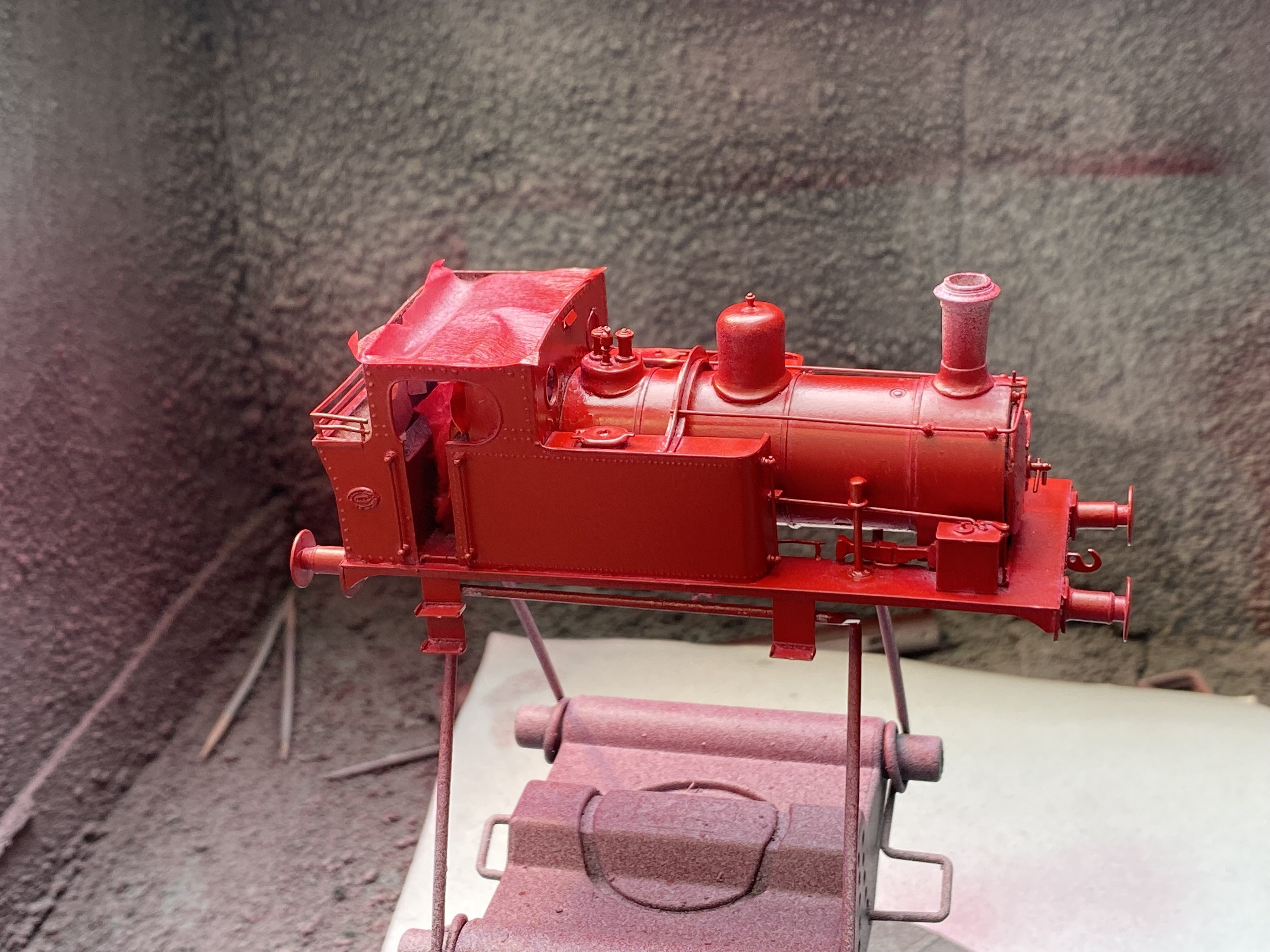
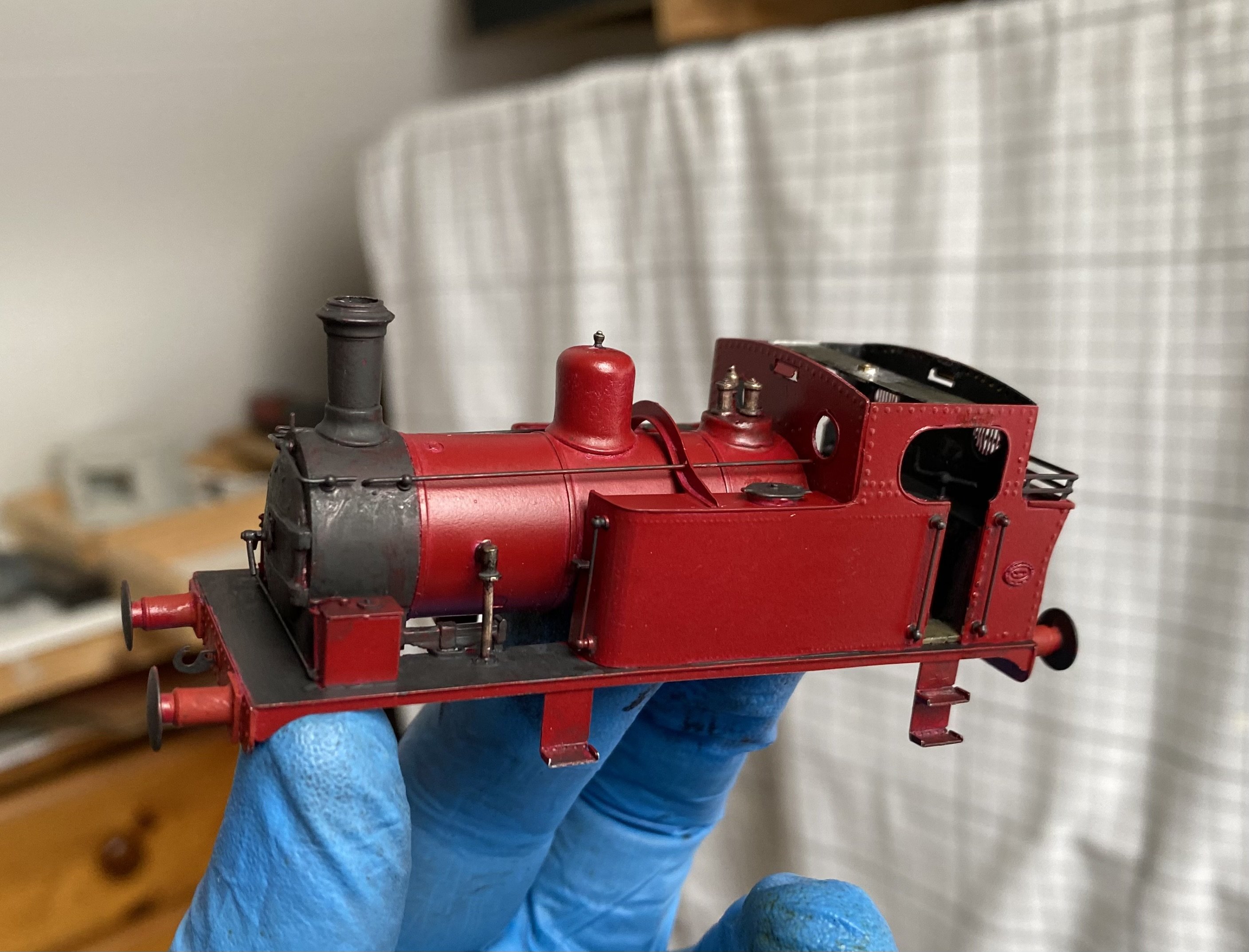
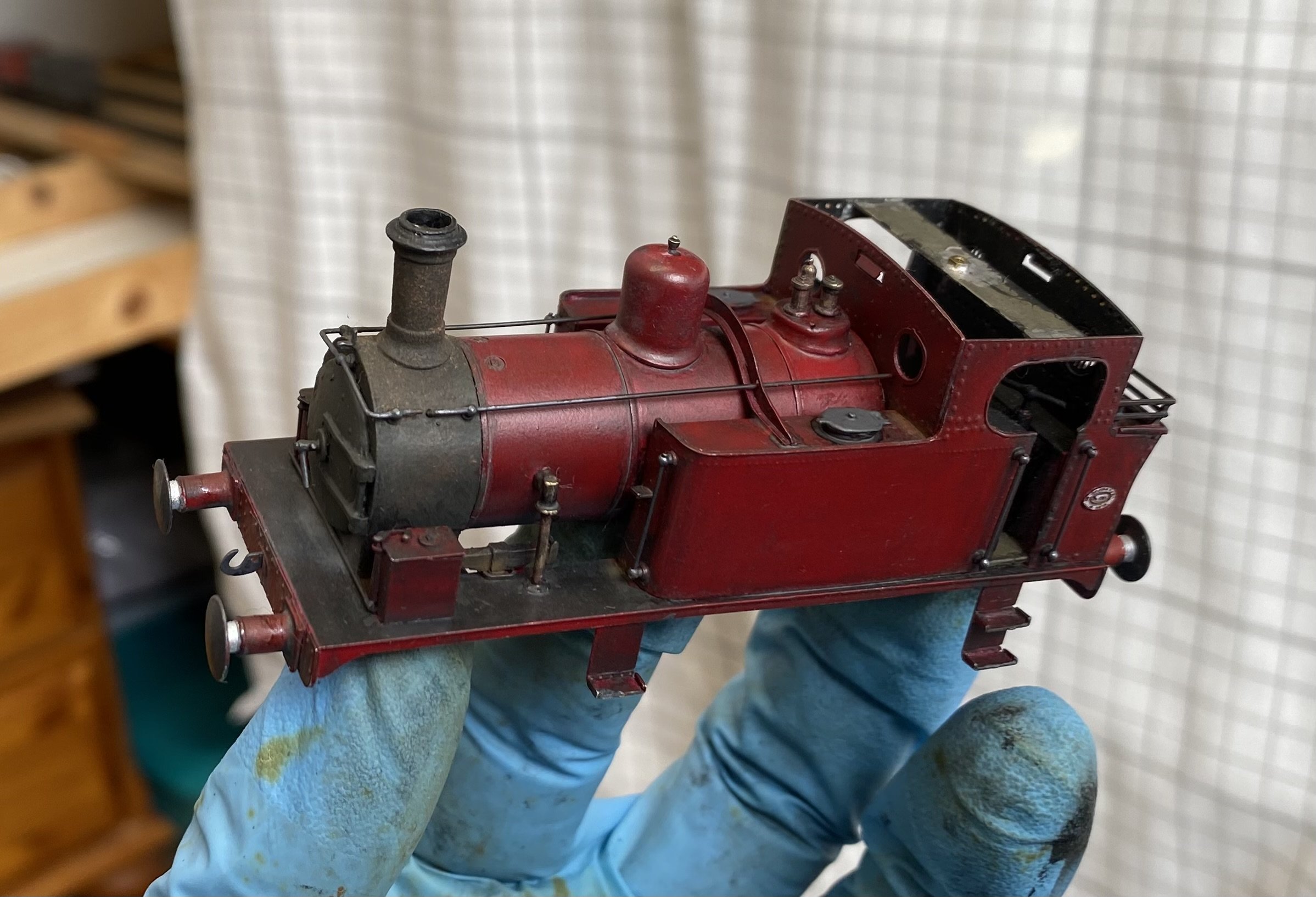
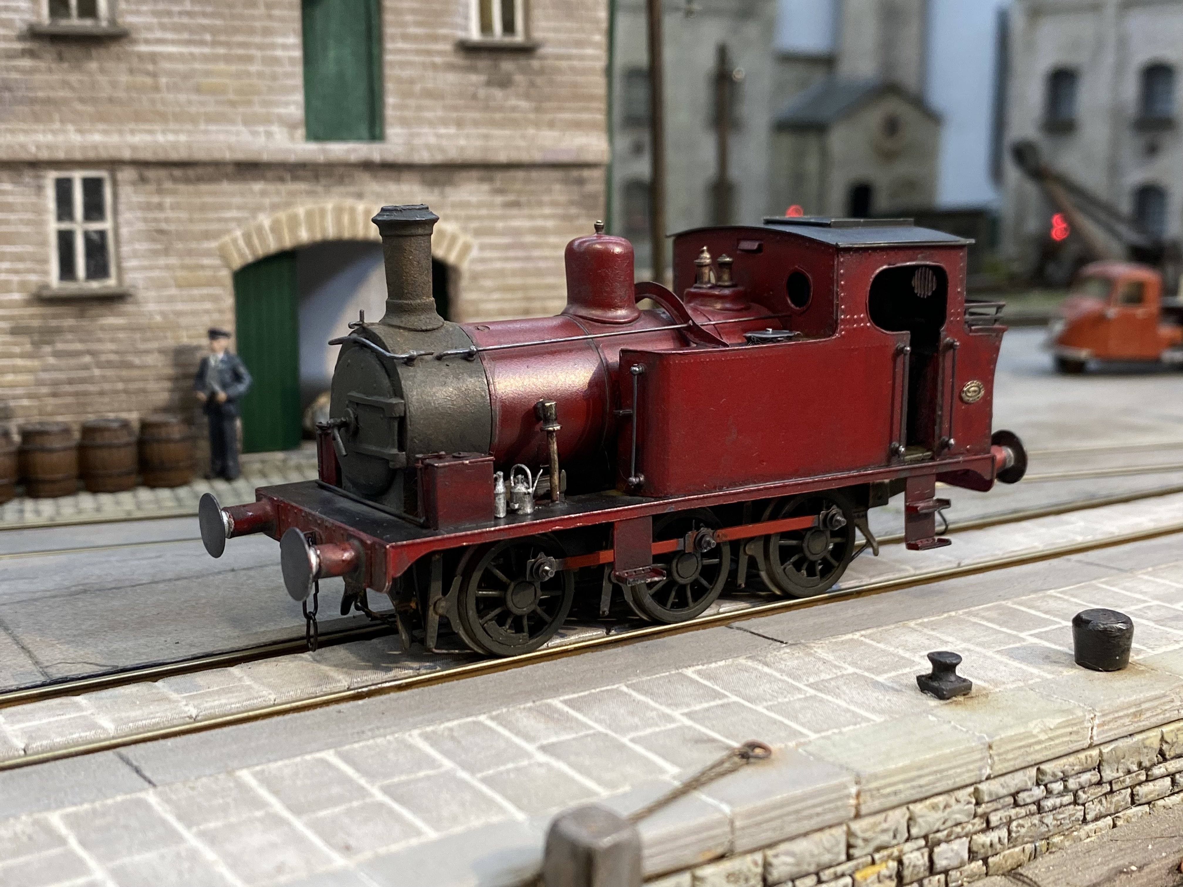
Paint for the Hunslett. First an overall coat of airbrushed Humbrol Crimson acrylic.. Then some Humbrol metalcote for the running plate and a matt black/leather/metalcote mix for the smokebox. Enamel this time. Paint stripped off some details such as the safety valves and whistle. ... and finally a thinner mix of the same stuff applied all over and wiped off. Glove nicely weathered. Some details touched up after the weathering wash. Oil cans are from ModelU Hunslett is just about finished now, bar a bunker load of coal. IMG_5899.MOV That's enough of grubby shunters for now. I hear the BCDR calling again. Alan
- 88 replies
-
- 17
-
-
-
Interesting Early Irish Railway photos
Tullygrainey replied to Westcorkrailway's topic in General Chat
Wonderful stuff. And what a great bunch of characters. I can almost hear the chatter and smell the pipe tobacco. -
Stellar job! Totally convincing.
-
Great jobs both. Proper model making!
-
Alan's grubby little shunters thread
Tullygrainey replied to Tullygrainey's topic in British Outline Modelling
There's a surprising amount of free space inside this Hunslett so a sound installation looked feasible. The sound chip was hardwired with all the joins covered with heat shrink sleeving. The speaker wires are connected to the chip via a mini-plug & socket arrangement which will allow the speaker to be permanently mounted and un-plugged if/when the chassis needs to come out. Testing the wiring. Despite a 50:50 chance of getting it right first time, I invariably wire the motor terminals the wrong way round so that it runs backwards with the controller set for forwards. Easily fixed but irritating. IMG_5818.MOV Yes, it all fits. The speaker is in the cab where the backhead should be (can't be seen) and the chip and stay-alive capacitor are in the boiler. IMG_5827.MOV Paint next. Alan -
Alan's grubby little shunters thread
Tullygrainey replied to Tullygrainey's topic in British Outline Modelling
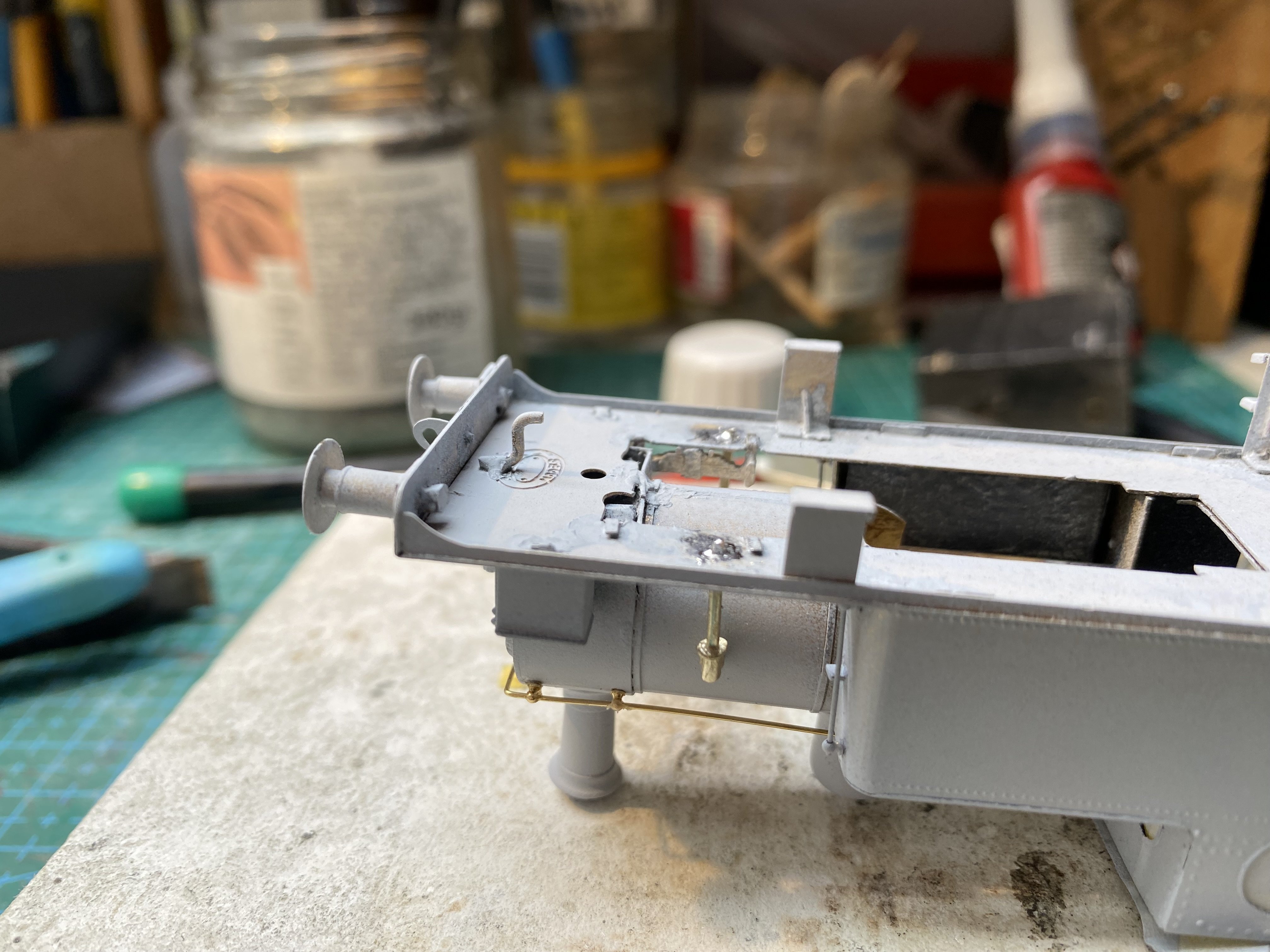
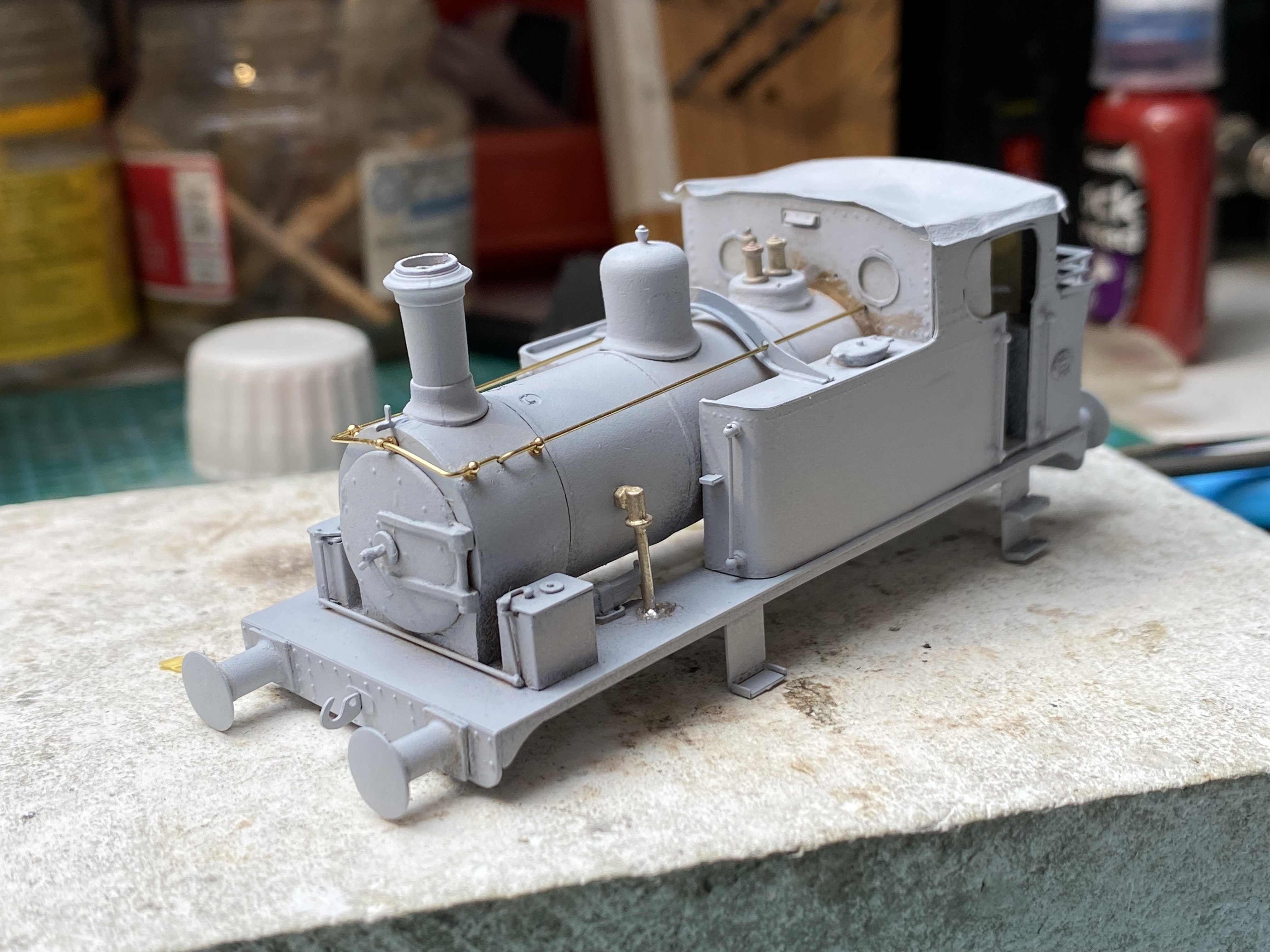
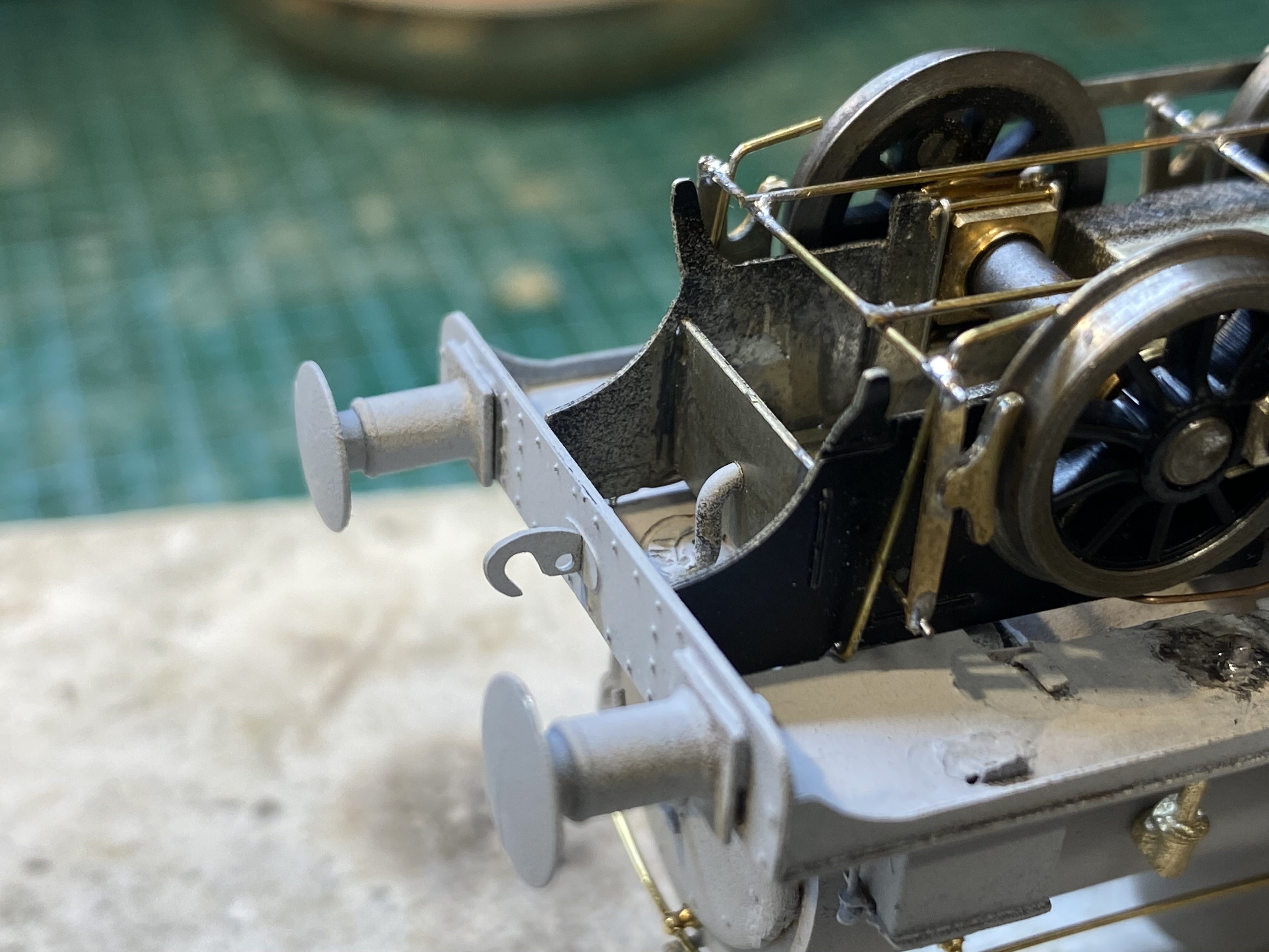
Cleans up nicely does Hunslett But nothing like a coat of primer to show up where the filler needs to go. I must have squandered about half a mile of brass rod getting those handrails the way I wanted them. I'm never entirely happy mounting chassis with bolts front and back, given the chance that tightening both could twist the chassis. So this one has a bolt at the back and this little bit of bent 1mm brass rod at the front which locates into a slightly oversize hole in the front chassis spacer. Chips soon Alan