Tullygrainey
-
Posts
1,139 -
Joined
-
Last visited
-
Days Won
60
Content Type
Profiles
Forums
Events
Gallery
Blogs
Everything posted by Tullygrainey
-

"Voiding the Warranty" - Mol's experiments in 21mm gauge
Tullygrainey replied to Mol_PMB's topic in Irish Models
Beautiful job Paul. Looking really well. No shame in glueing white metal castings. In my experience, it's nigh on impossible to solder whitemetal chimneys, domes and smokebox doors in place and I never attempt it. Why risk melting the casting whilst trying to get enough heat into the job when you can use glue which gives you time to adjust the position of everything. It's what 5 minute epoxy is for. -
Took a while for that penny to drop
-
Some more pics of progress on ThreePee (Patrick's PP). Alan

- 860 replies
-
- 14
-

-

-
Brilliantly quirky and, well just brilliant!
-
Inspirational! Excellent weathering, as always.
-
That's a sensible idea David and I always intend to do that. Then laziness takes over
-
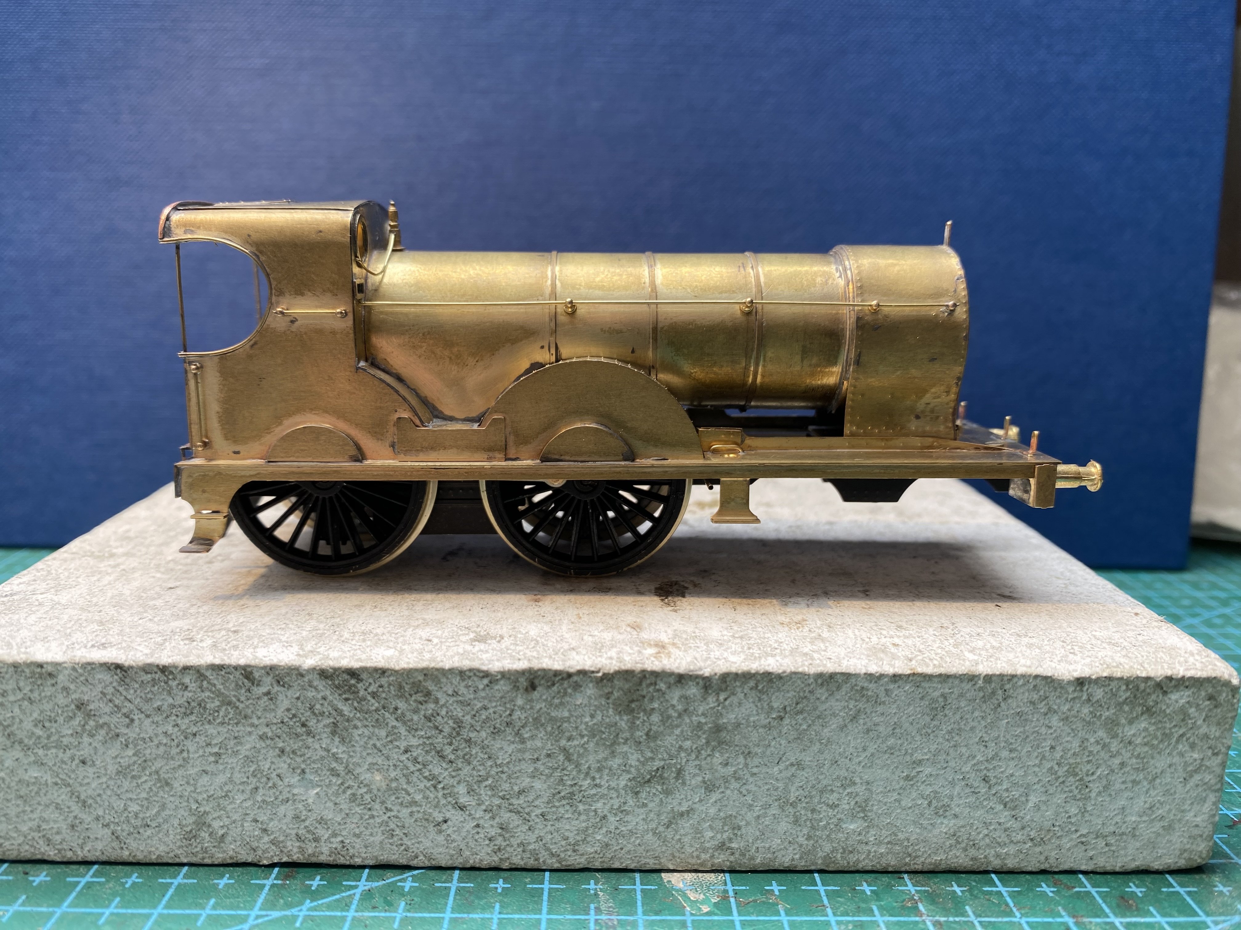
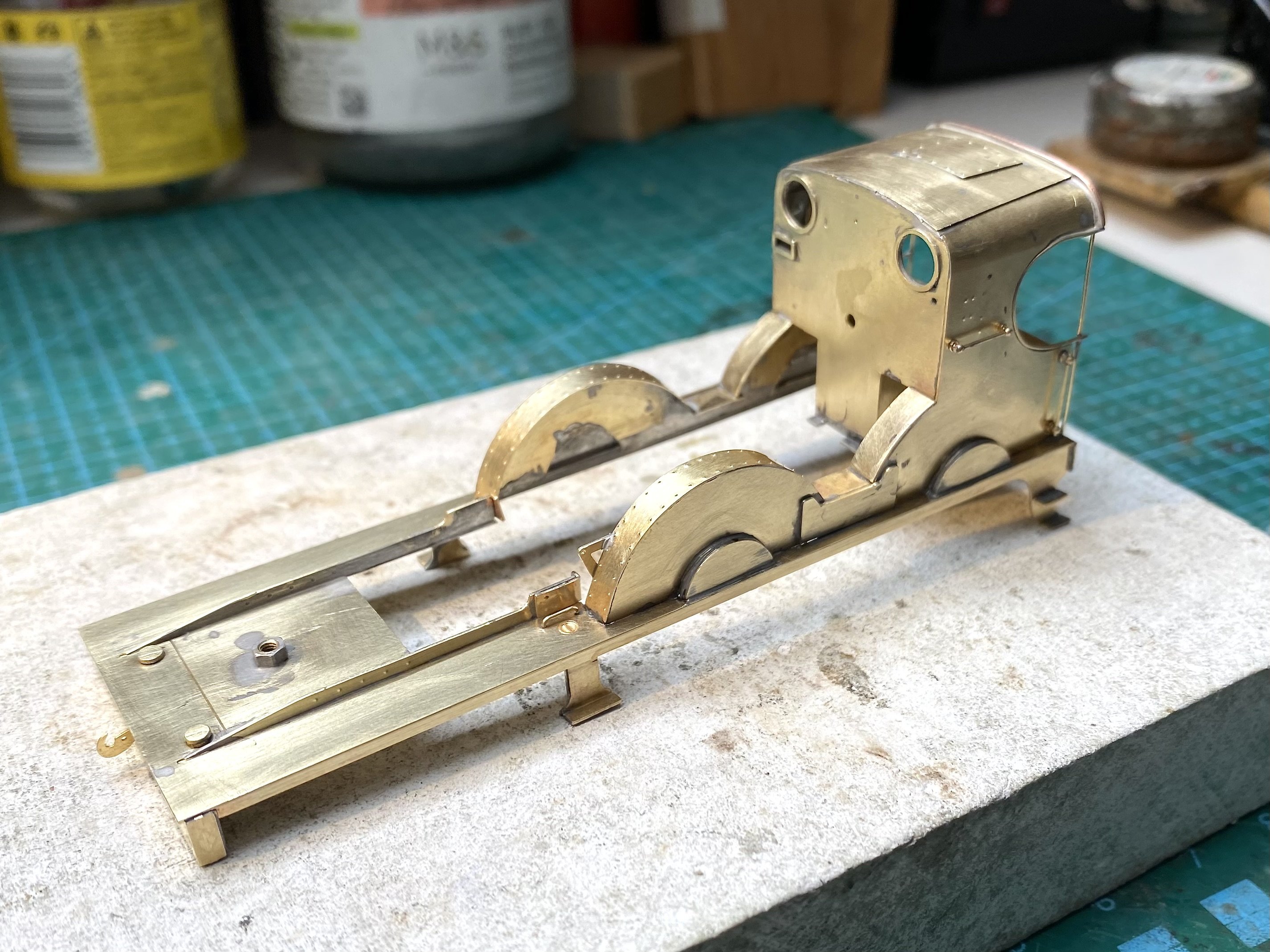
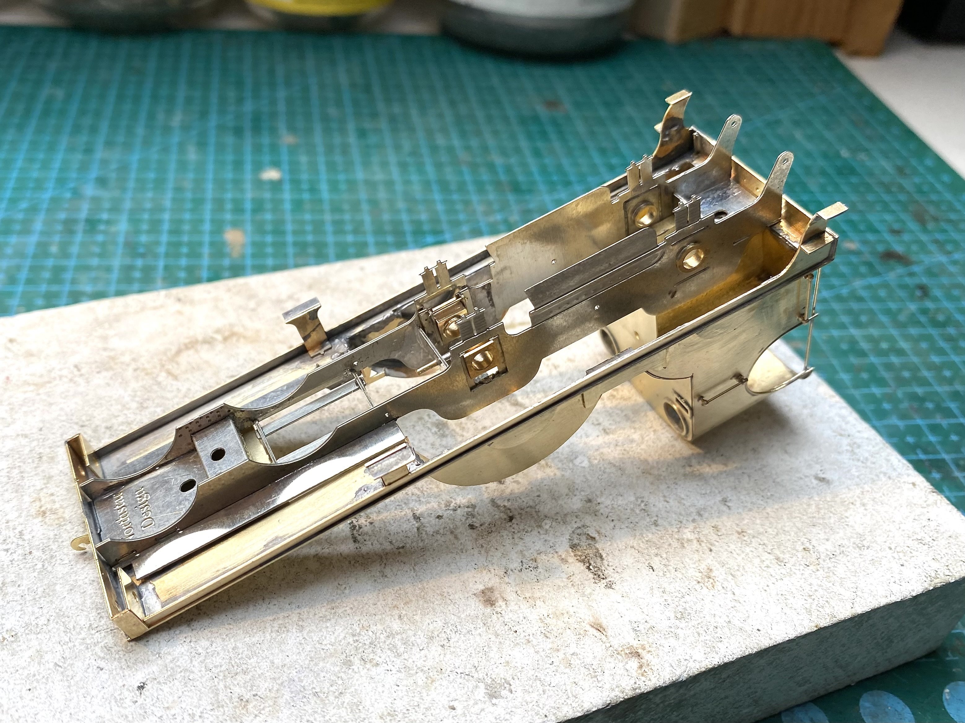
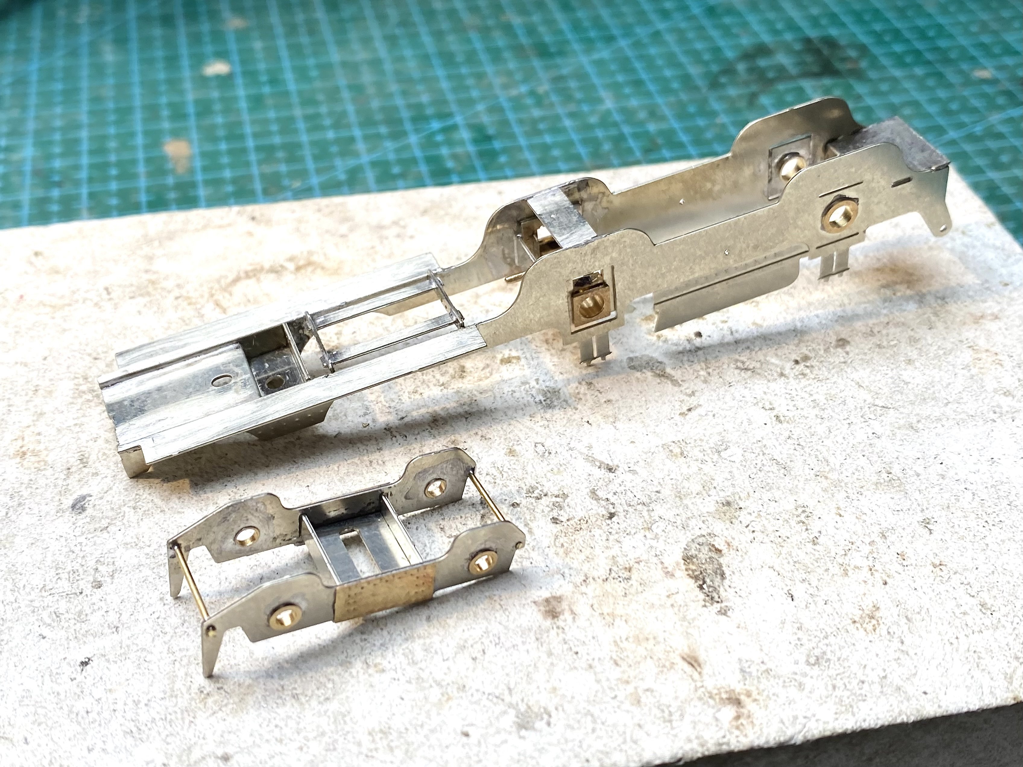
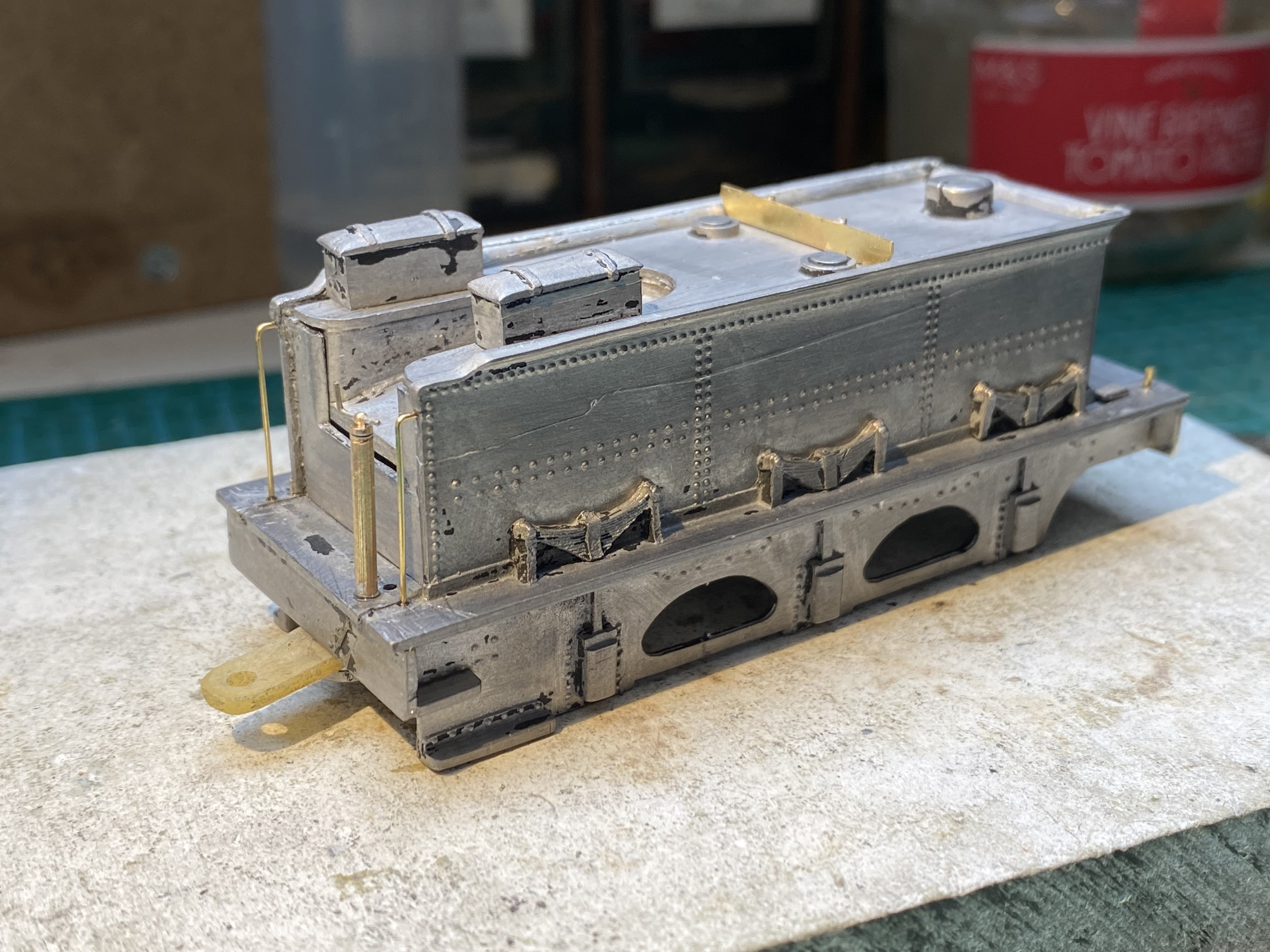
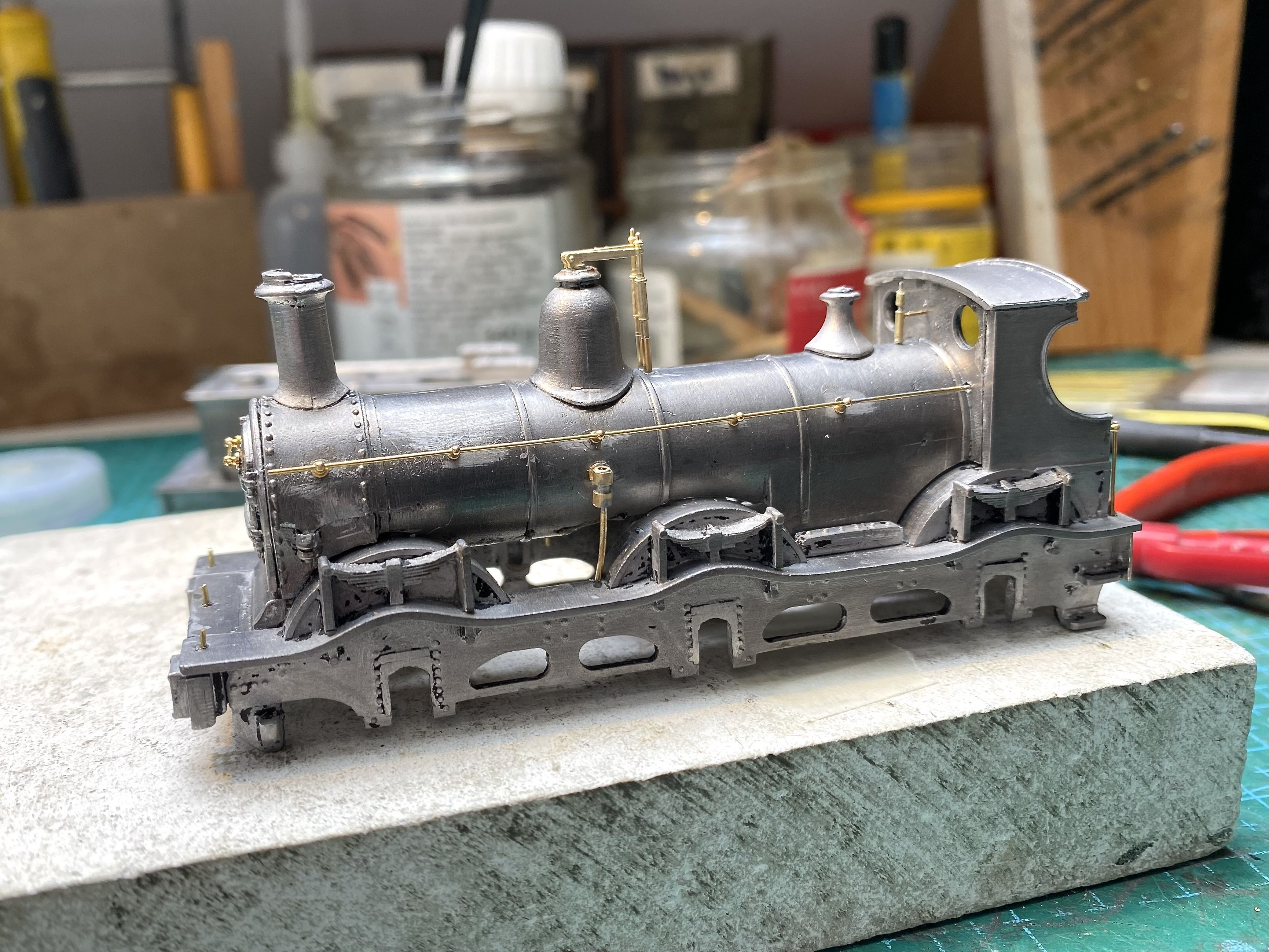
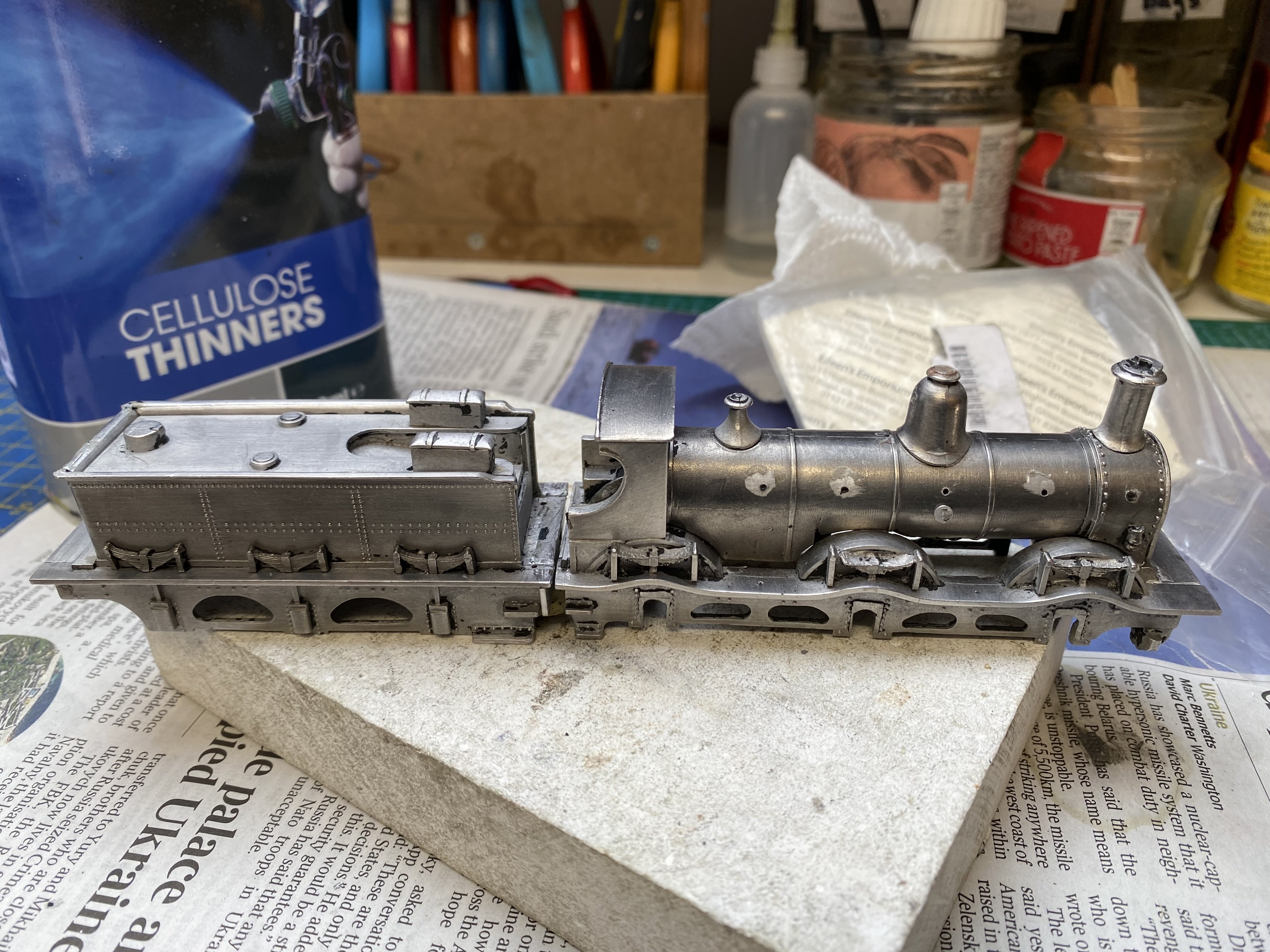
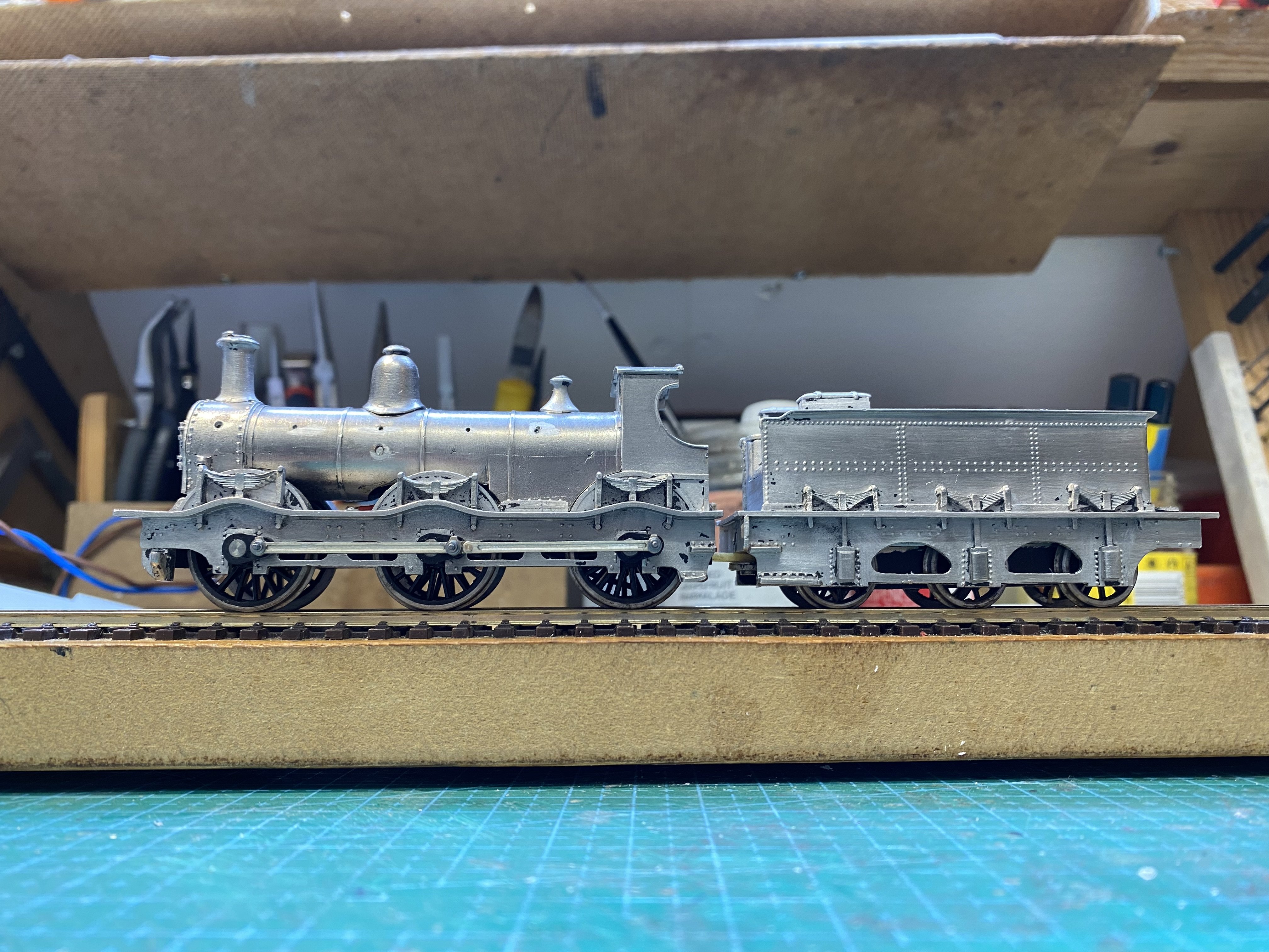
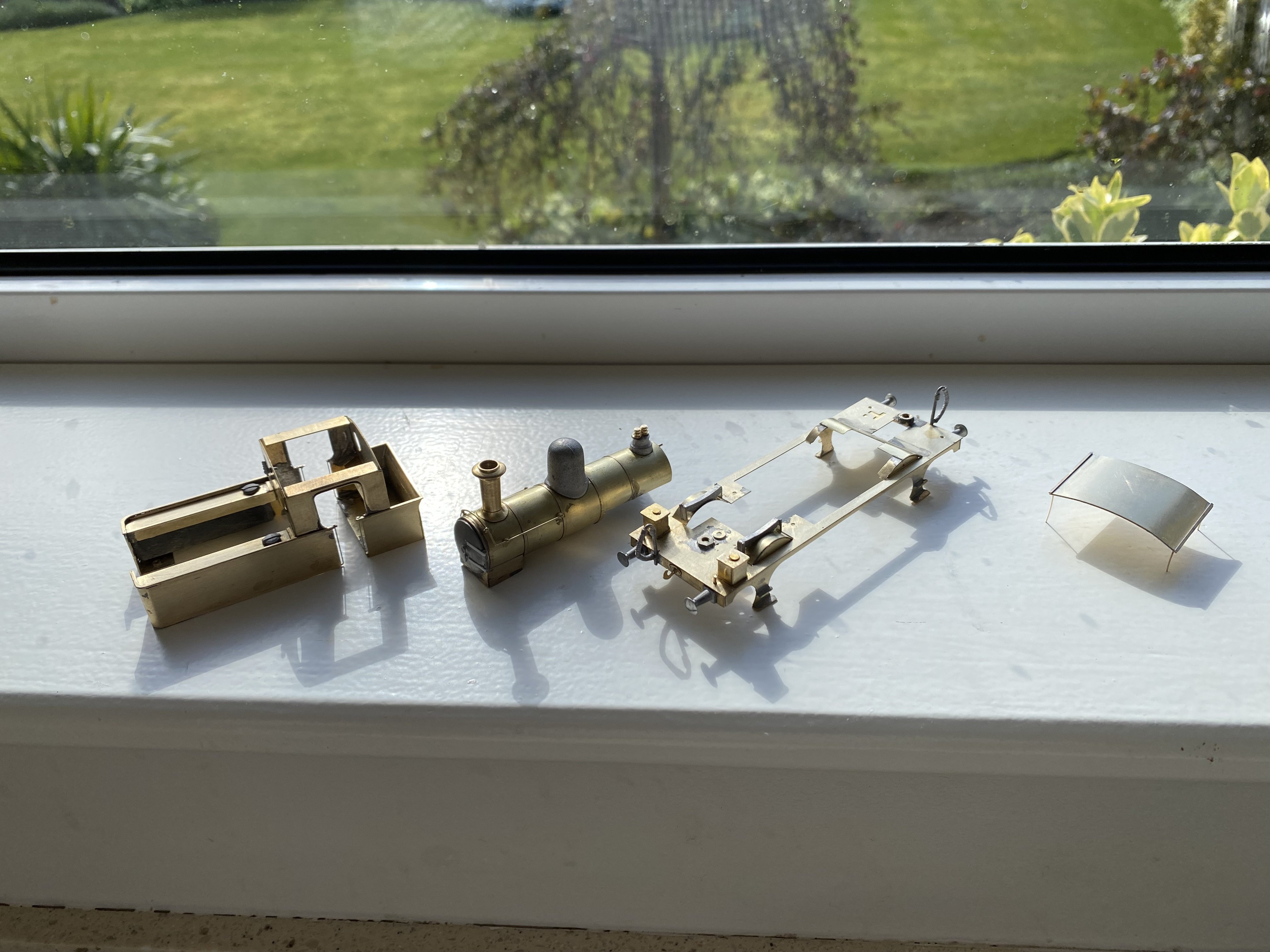
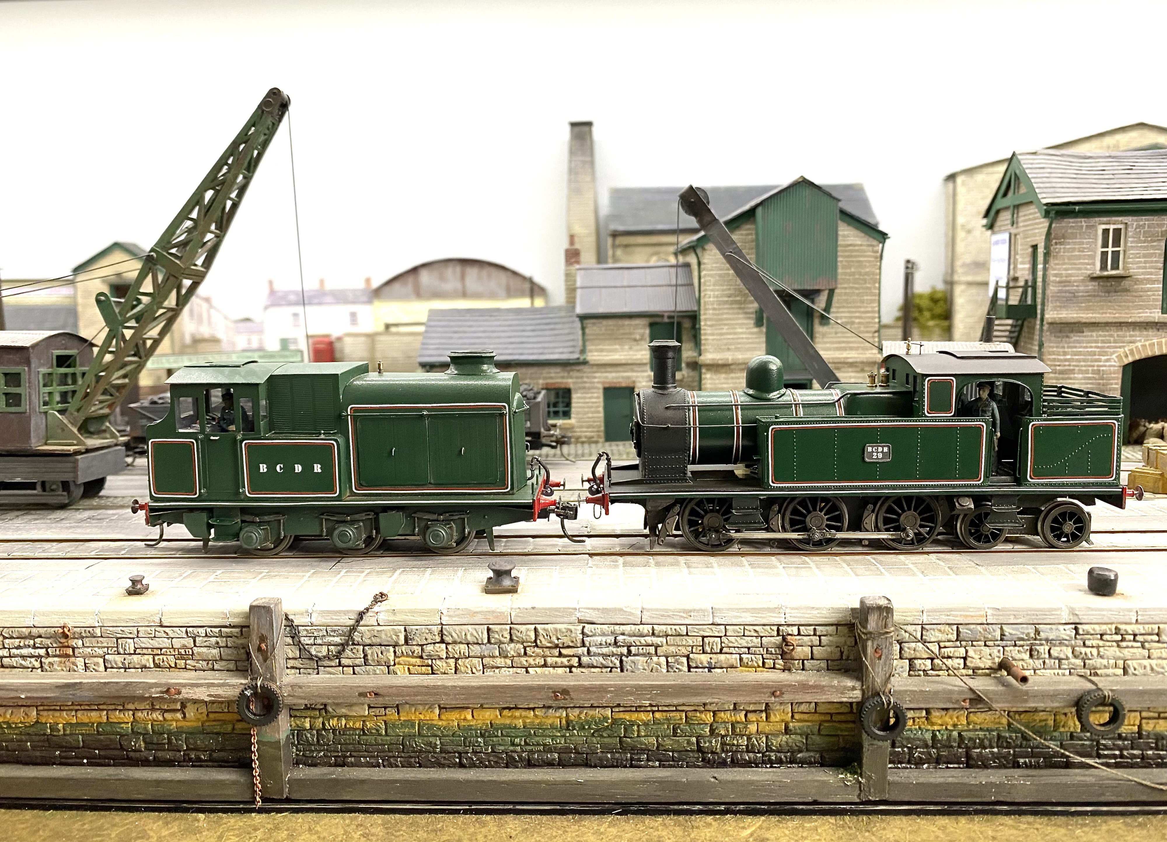
A strong sense of déjà vu hereabouts as another GNR(I) PPs 4-4-0 makes its way through the erecting shop. This one is destined for Patrick @Patrick Davey. The kit is available from Studio Scale Models these days but it's essentially the same kit I built for Kieran Lagan recently (see 12/11/25 post above) from etches originally designed and marketed by Northstar. Chassis is compensated with a fixed rear axle and hornblocks on the other one which rocks on a horizontal beam fixed to a frame spacer. Some of the lessons learn on Kieran's build are proving useful here though I'd forgotten just how tricky some of the jobs are. Those splashers, big and small, take a long time to get right, as does the cab roof and the whole running plate is very floppy and difficult to keep straight as bits are gradually added. However, it's a nice kit and it's coming together well so far. Boiler and smokebox next Alan
- 860 replies
-
- 10
-
-
-

-
That is a radical transformation! You'd be hard pressed to guess the model it evolved from. A lot of painstaking work but worth it for the end product. You've certainly captured the essence of Slieve Gullion. Great to see projects like this. Thanks for showing us the process.
-
This resonated with me John, having come up against the same issue only a day or two ago. I think I might follow your lead and start using my London Road Models tapered jig axles again.
-
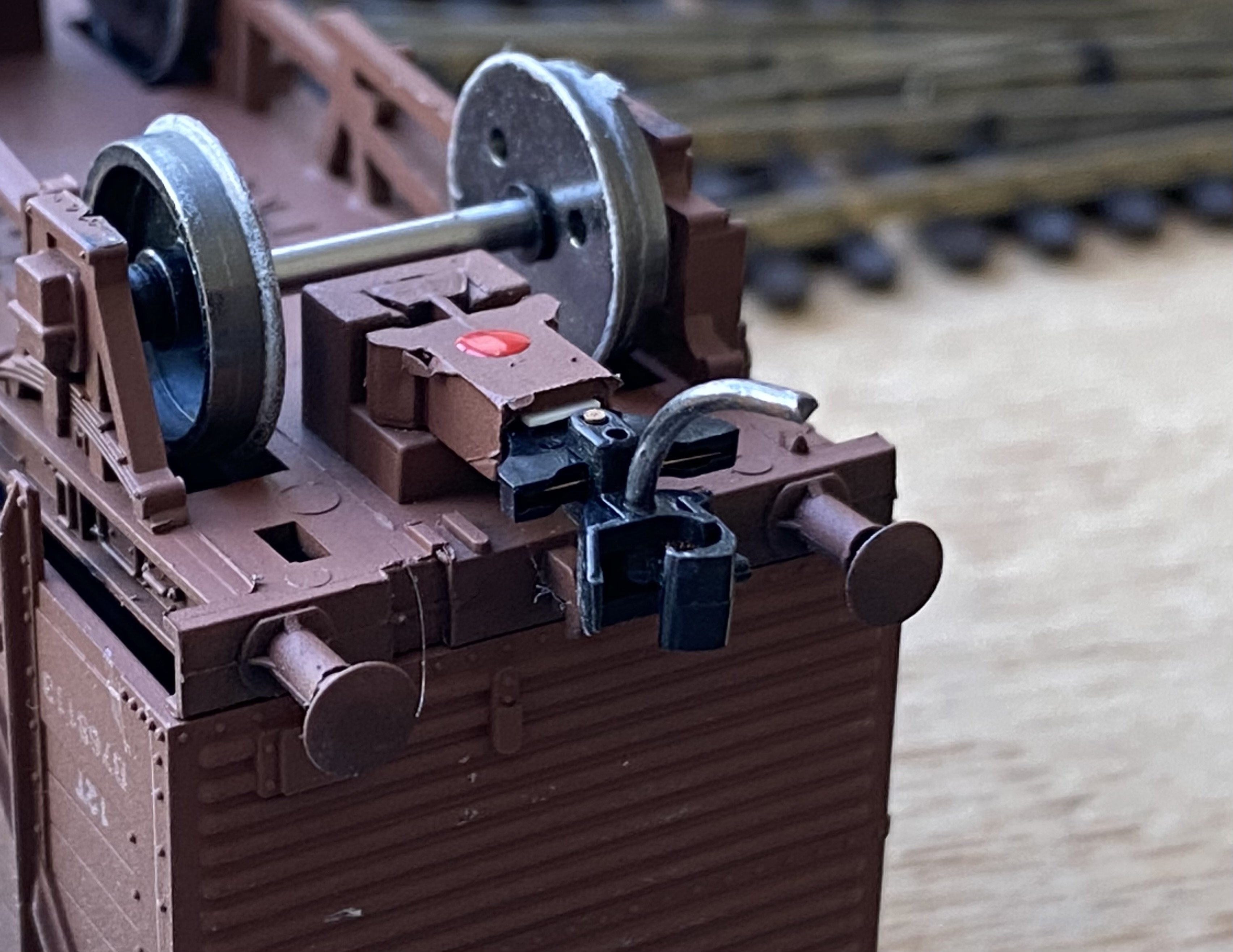
With the Kirtley's chassis out of commission for the time being, I've done some more work on the body shells, replacing handrails and adding some missing details. Still need to source some buffers. Nothing in the drawer to suit.
-
Probably David. I'd say inserting the crankpins caused the cracking in the first place but in use, the weight would surely have finished the job in the end. Replacement rather than repair is probably the better option now, with a bit more care next time!
-
The Kirtley comes unstuck. Having arranged some chassis mounts for loco and tender and fitted an insulated drawbar, I stripped the Kirtley of its black paint to reveal some quite nice white metal castings. Then this happened... It's difficult to see in the photo but the crank on the centre axle has fractured. What seems to have happened is that inserting the crankpin into the crank - standard Gibson practice for wheels, the crankpin cuts its own thread as it's screwed in - weakened the crank and caused it to break. On examination, 4 of the other 5 have cracks. I think John @Mayner may have alluded to this possibility in an earlier post above. I should've listened Having a think about how to proceed. Repairing the crank is probably futile. The others may go the same way. I'm happy with the Gibson cranks but if I use them again I'll ream the holes a bit before inserting the crankpins and secure them with Loctite or similar. Parked for now. (It, not me) Alan
- 860 replies
-
- 11
-
-
-
"Voiding the Warranty" - Mol's experiments in 21mm gauge
Tullygrainey replied to Mol_PMB's topic in Irish Models
Excellent. Your little jig is a fine bit of work. Beautifully made and it seems to do the job well. A useful addition to your tool kit. -
A little square of thin Plasticard will do the job
-
Beautifully crisp work with the plasticard David. Now the loco is painted, it would pass for a brass photo etch.
-
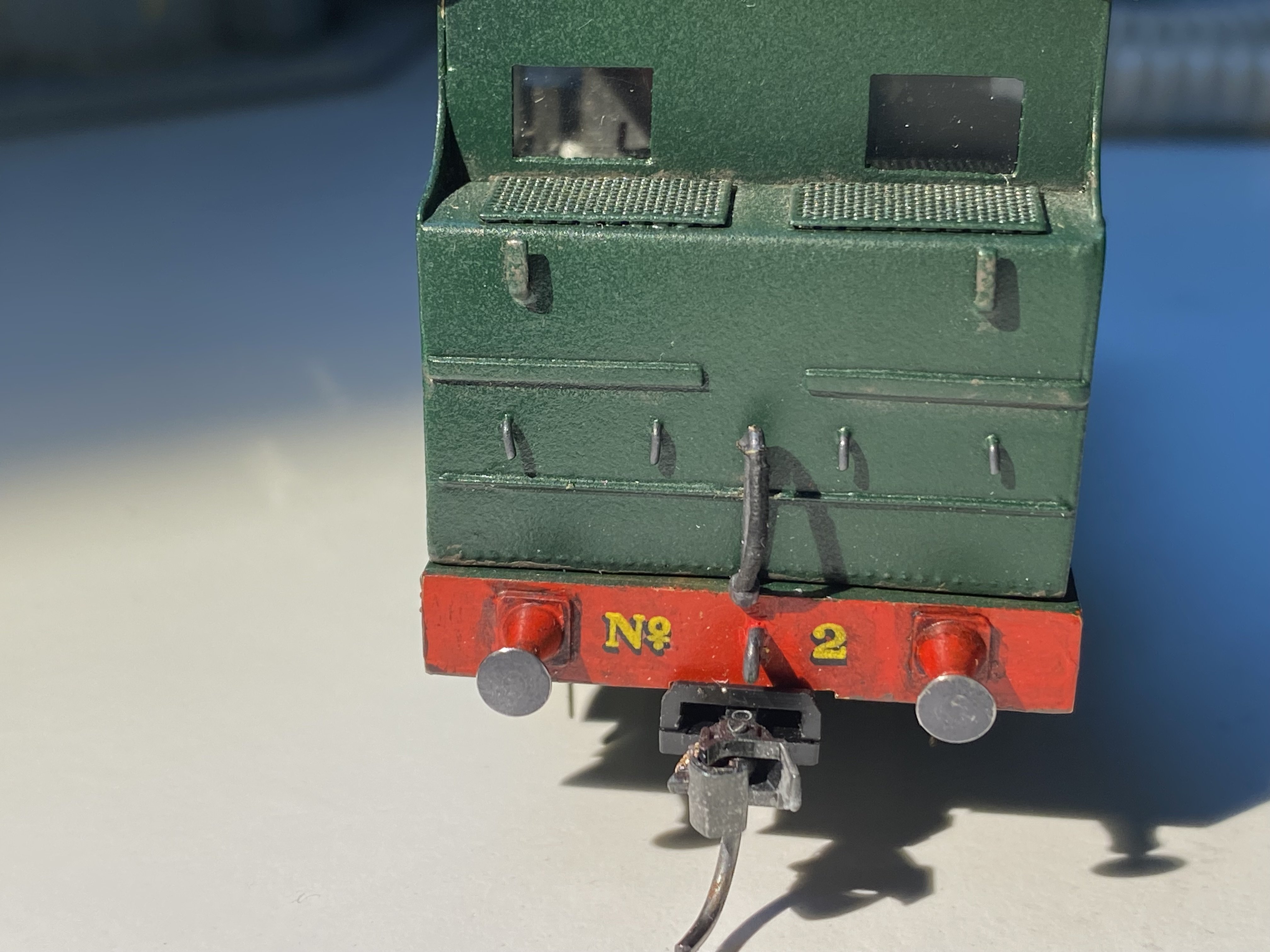
I used LSWR/SR ones too on my BCDR locos. Not strictly accurate but I'm content with them and nobody's pointed out an error yet! These are from HMRS Sheet 9.
-
I'd need to consult the owner about that. Kieran will take over from here to do the paint, transfers and finishing so the final decision will be his. There are still a few things to sort before that, including cab detail and deciding on a home for the decoder. It's in the bunker at the moment but could conceivably fit in the boiler, though getting a stay-alive in there too might be a bit of a squeeze. Don't rush your build! The detail you're putting into it is worth spending time on.
-
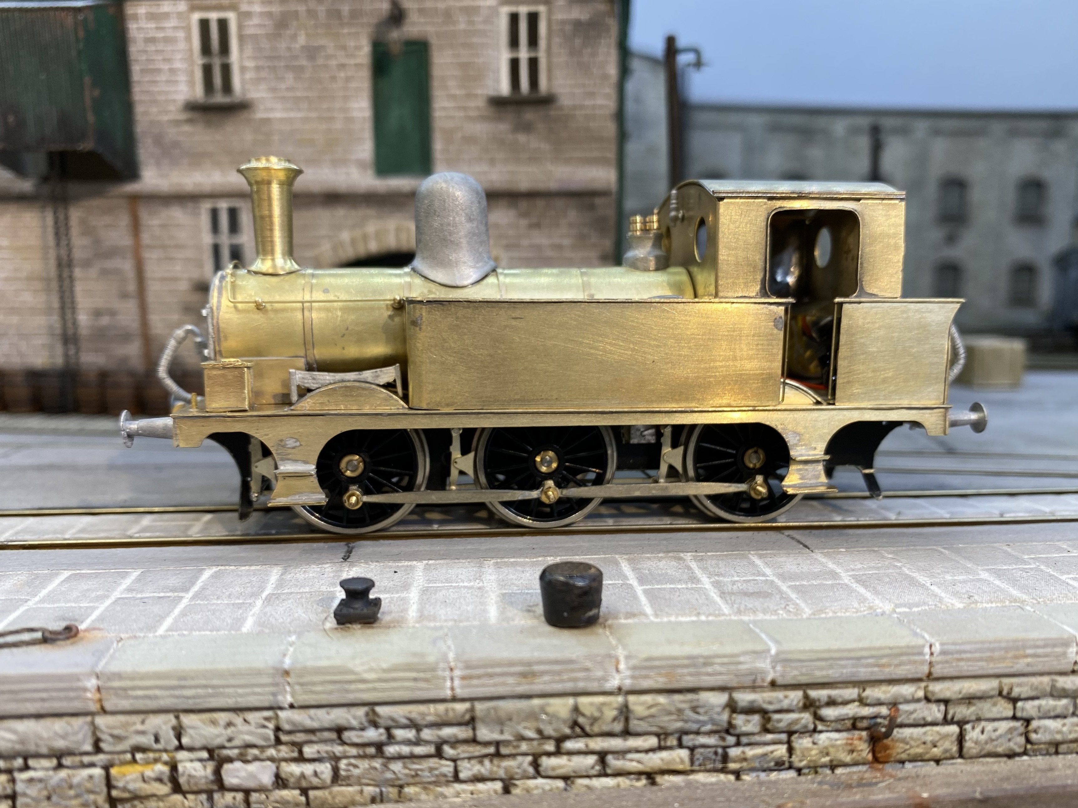
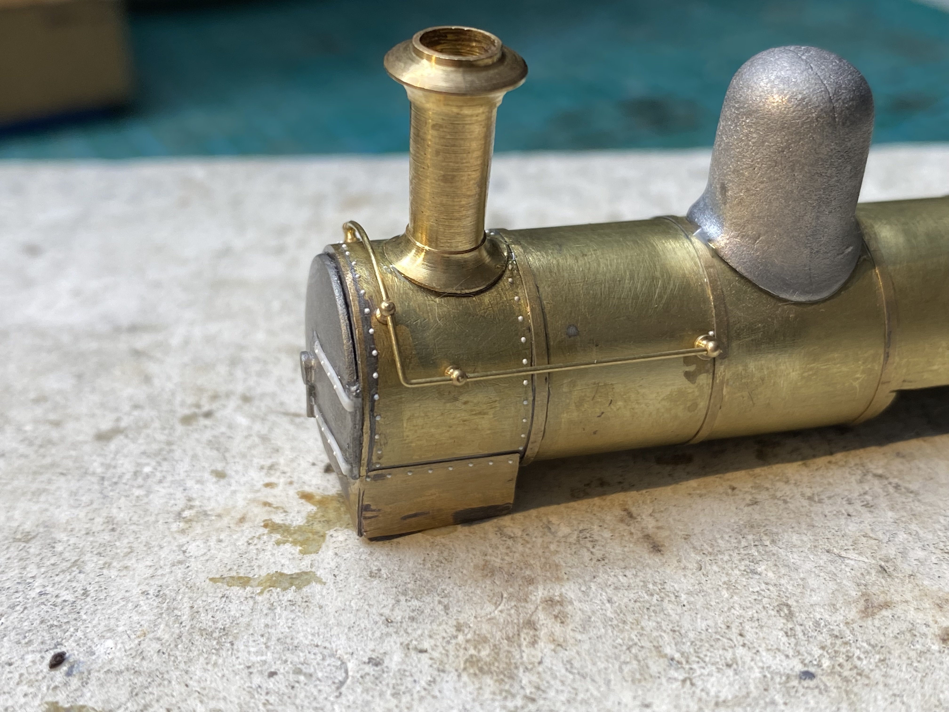
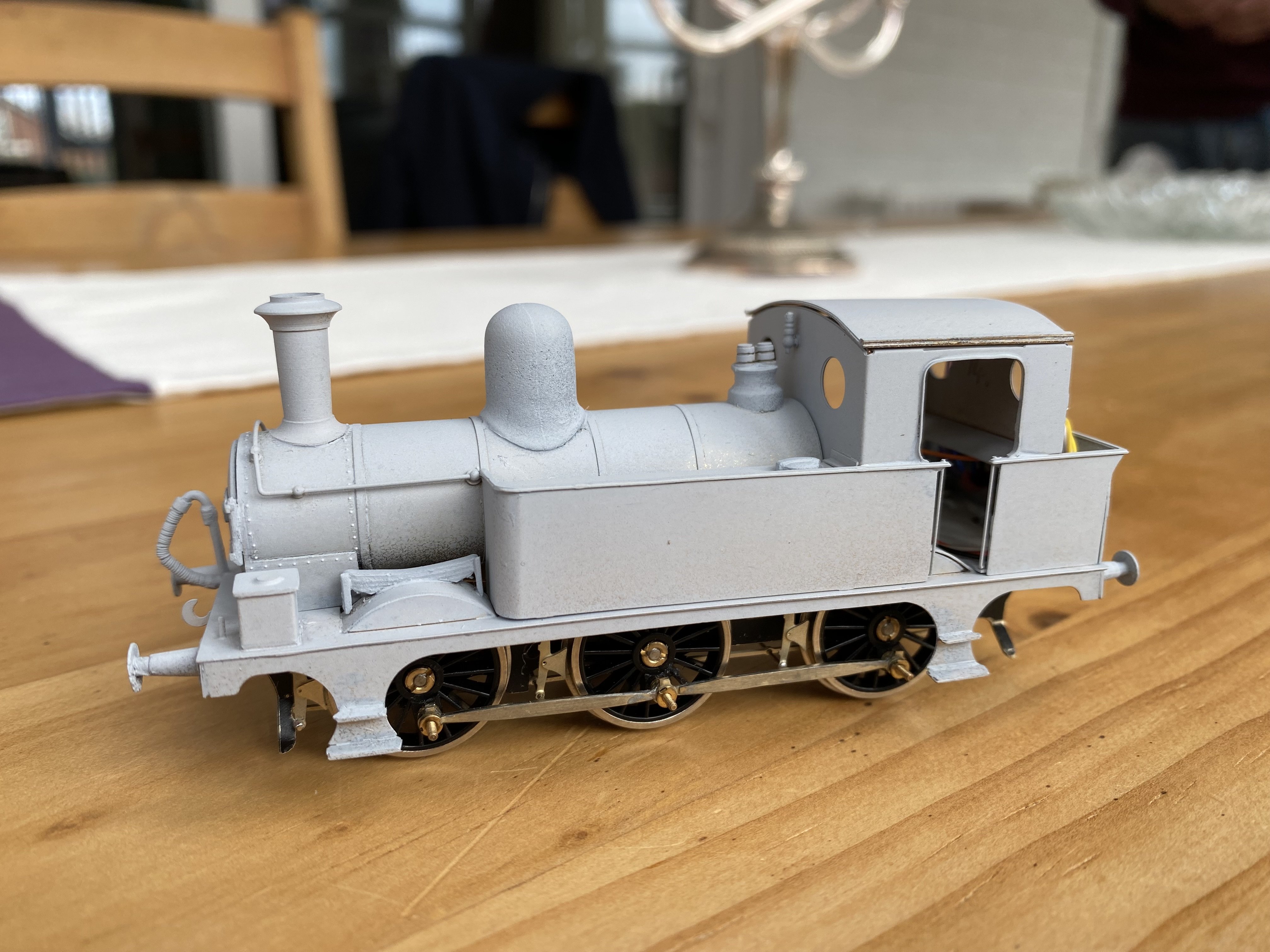
The J26 is getting there. Basking in the sunshine after a good scrub.... ... and together in all its brass brassiness. Some Railtec rivets... ... and turned out in builder's photogenic grey. Roof will be fitted properly in due course. First runs under DCC at Loughan Quay.... IMG_4839.MOV ... and again on its home turf, Kirley Junction. J26.mp4
- 860 replies
-
- 11
-
-
-
Love that DIY brass clamp. Inspired! So simple, so effective
-
N Scale Ballywillan, Co Longford.
Tullygrainey replied to Kevin Sweeney's topic in Irish Model Layouts
That is just a delight! -
So very sorry to hear your news. I'm sure I speak for every one here on the forum in sending condolences on your loss and best wishes as you deal with the daily challenges. Alan
- 241 replies
-
- 10
-
-

-
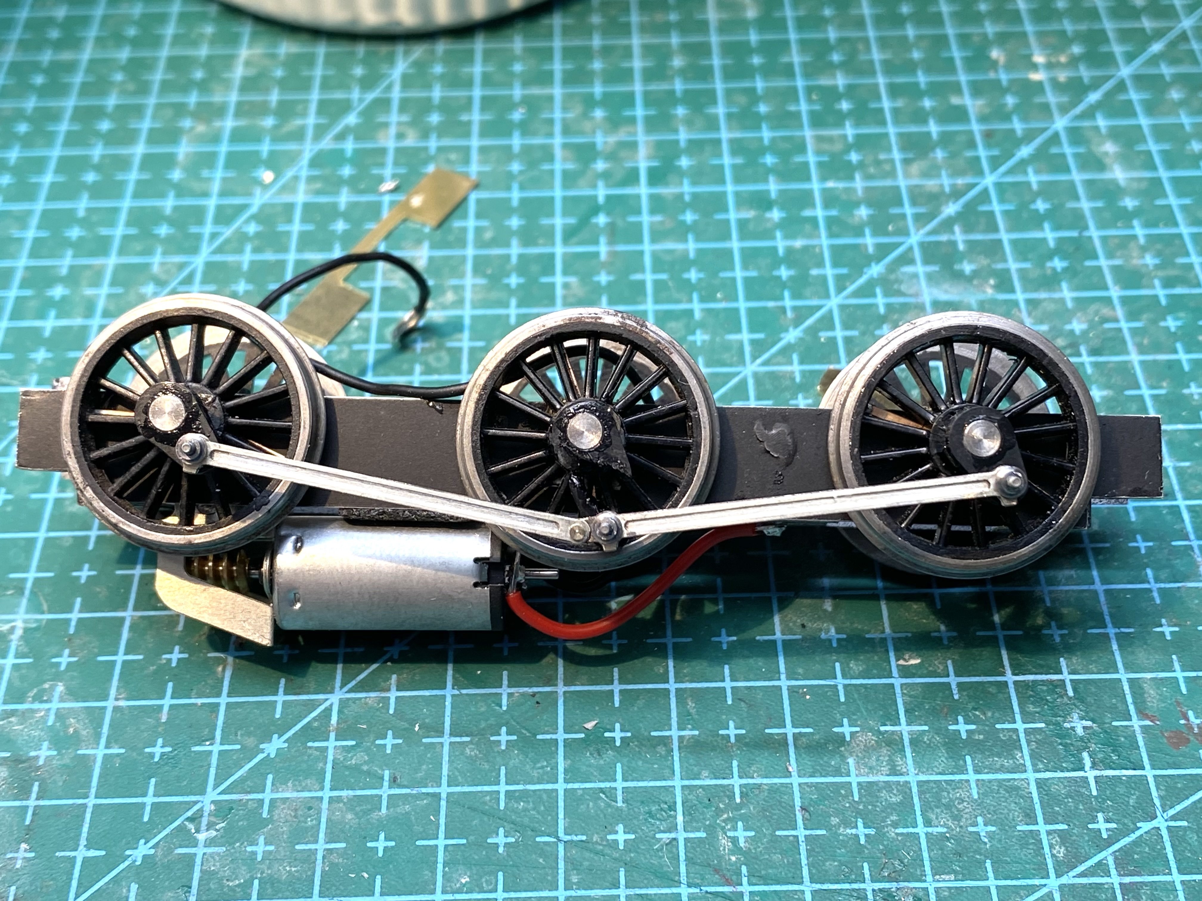
The Kirtley lives! IMG_4832.MOV My first attempt at a live chassis arrangement. Loco needs some proper body mounts and the tender needs attention to level it up but now I know it works, it'll be worth some more effort to make it look and go a bit better. Alan
- 860 replies
-
- 12
-
-
-
"Voiding the Warranty" - Mol's experiments in 21mm gauge
Tullygrainey replied to Mol_PMB's topic in Irish Models
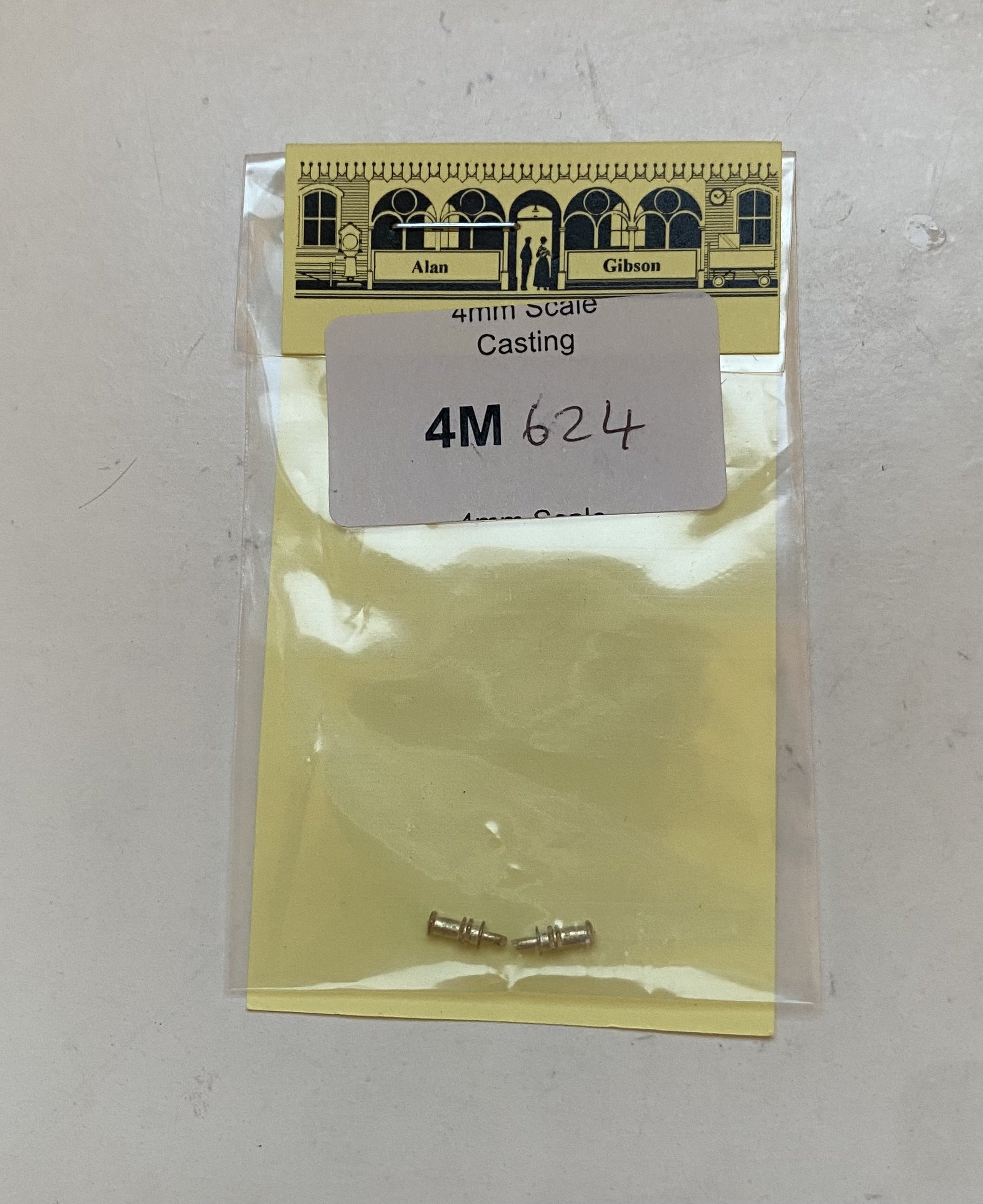
Very tidy Paul and great attention to detail. Ross pop valves do seem to be hard to come by. I had a small collection pillaged from second hand Hornby 0-4-0 Smokey Joes and the like but I've used them all up now. These from A Gibson aren't quite right but might be usable with work though it might be just as easy to make some from scratch as you suggest!
-
There’s always the desire to conceal them as much as possible for cosmetic reasons but from a practical point of view this makes sense. It’s also a good argument for placing them underneath the frames.
-
You might get away with contacts hooked over the flanges - depends how much deflection your CSB allows - but it would be tight. It's only the front axle that's a problem. There's plenty of room above the other two. You could consider having the hooks make contact with the wheels a bit further down from the top. There's slightly more room there. I considered going underneath with this one. You have the brake pull rods to contend with but it should be possible to work round them. As I said, a pain!