Tullygrainey
-
Posts
1,139 -
Joined
-
Last visited
-
Days Won
60
Content Type
Profiles
Forums
Events
Gallery
Blogs
Everything posted by Tullygrainey
-
Here we go. When he was making the models I’d say Gareth had to trawl the internet for good photos
-
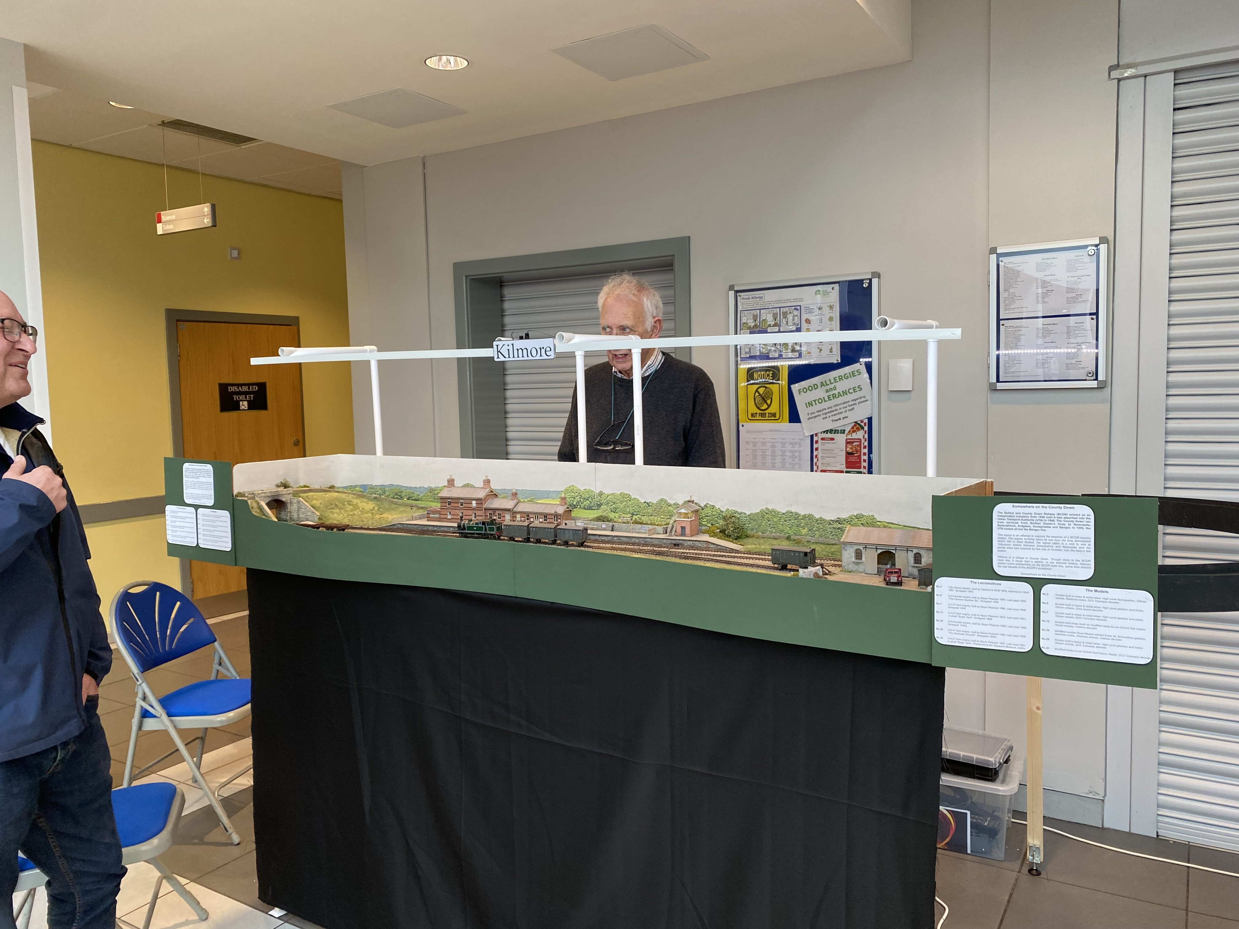
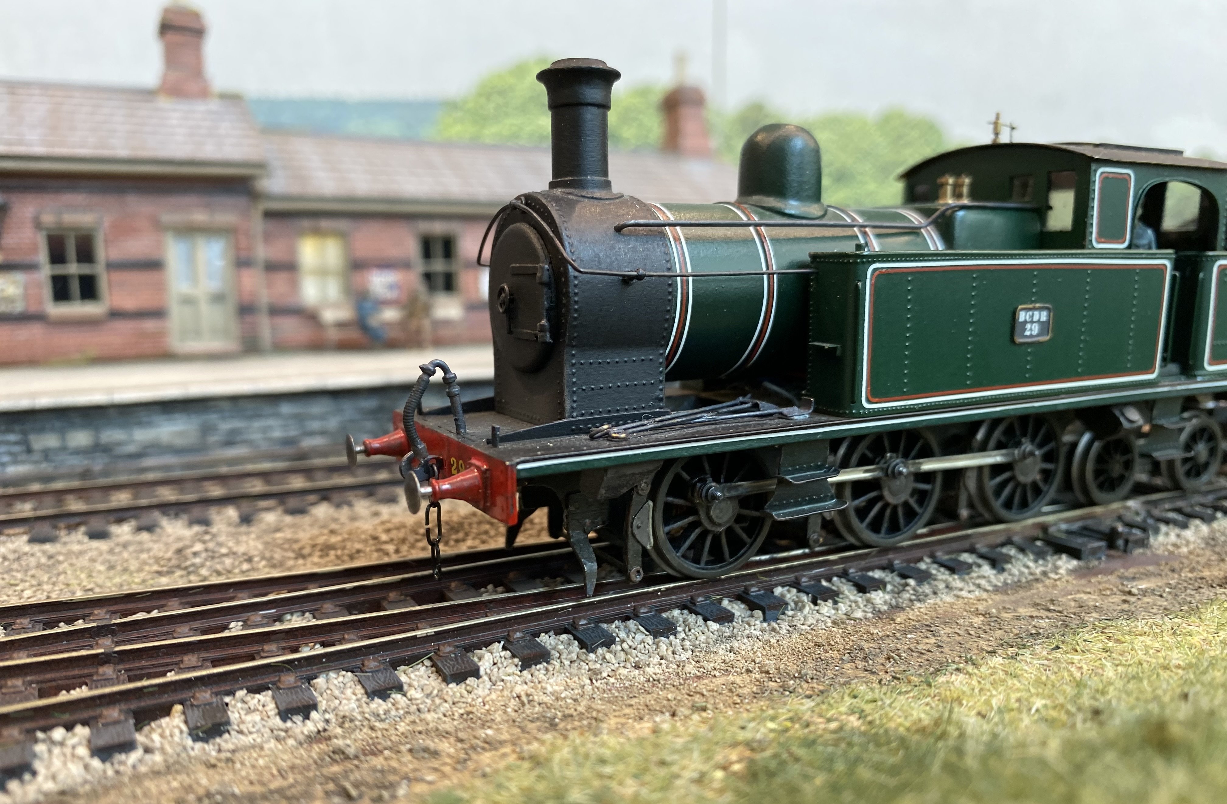
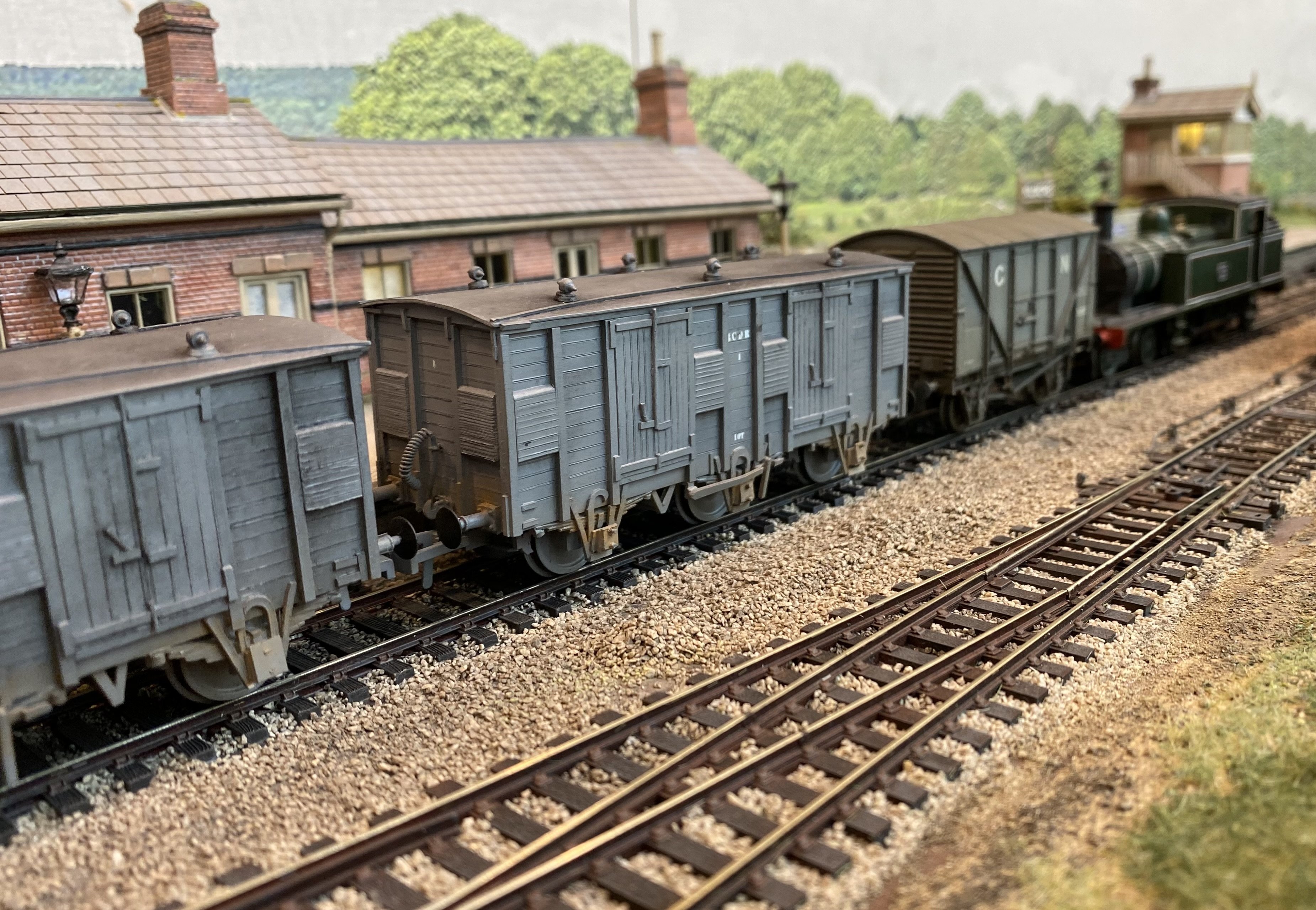
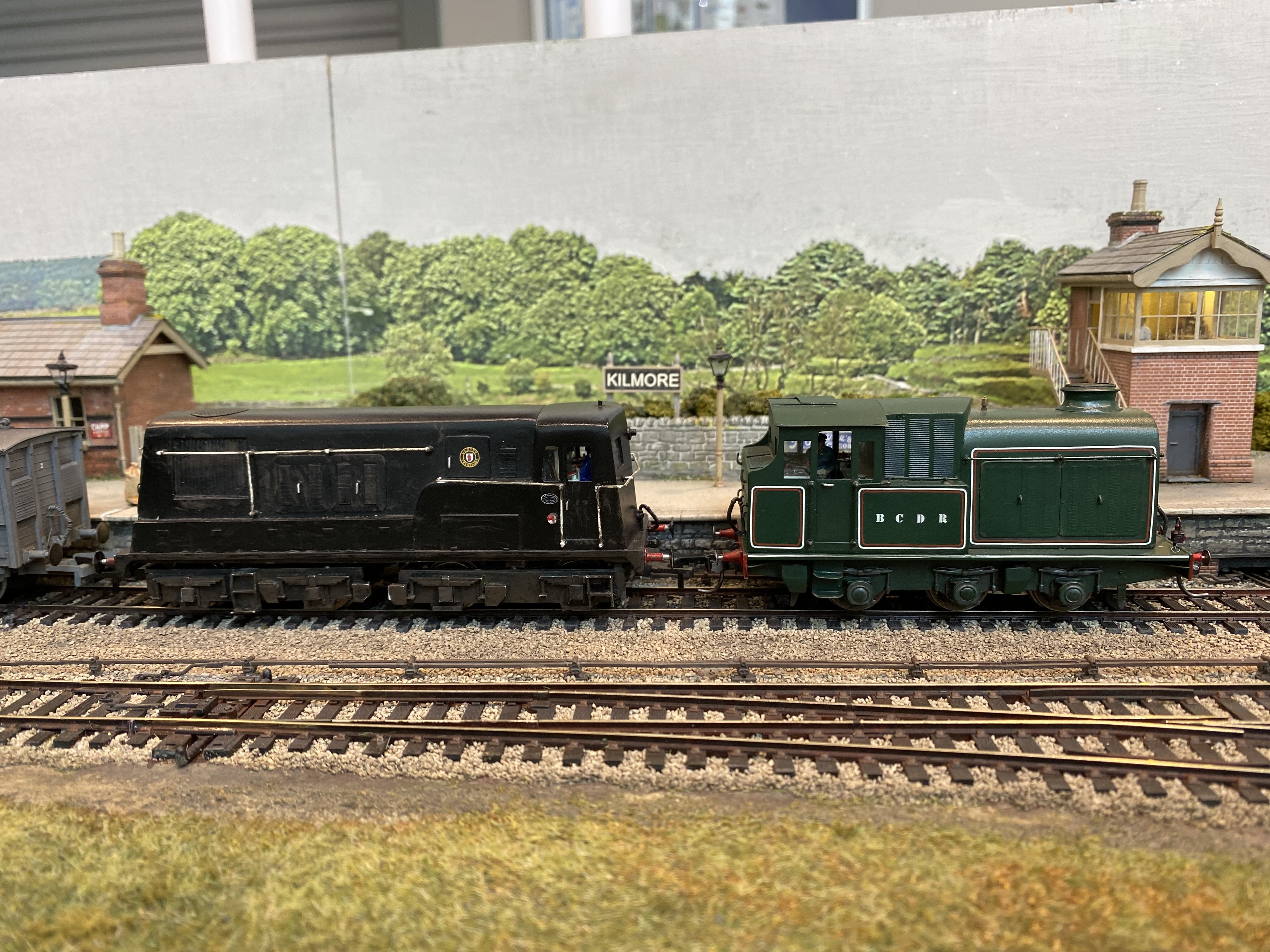
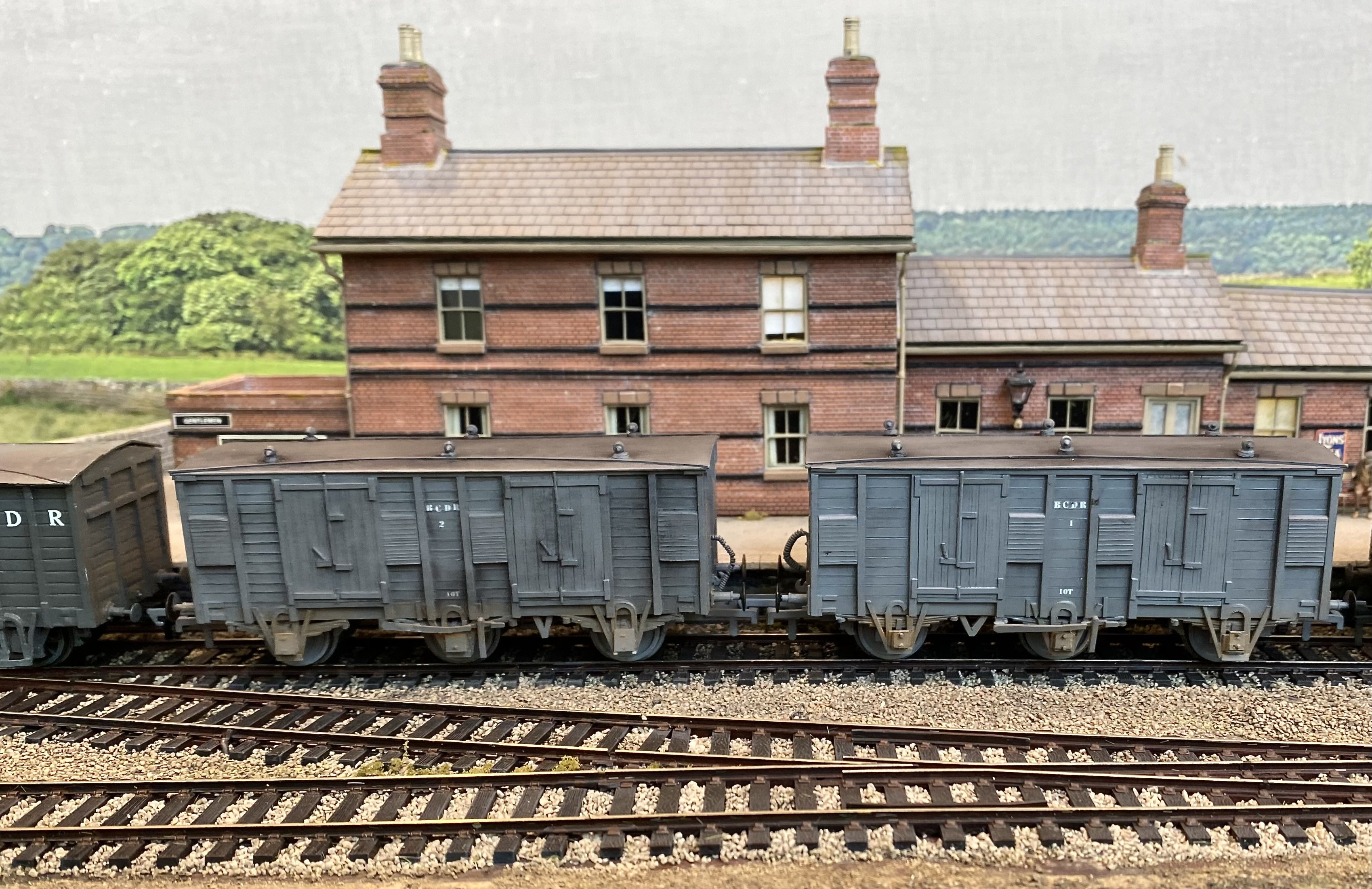
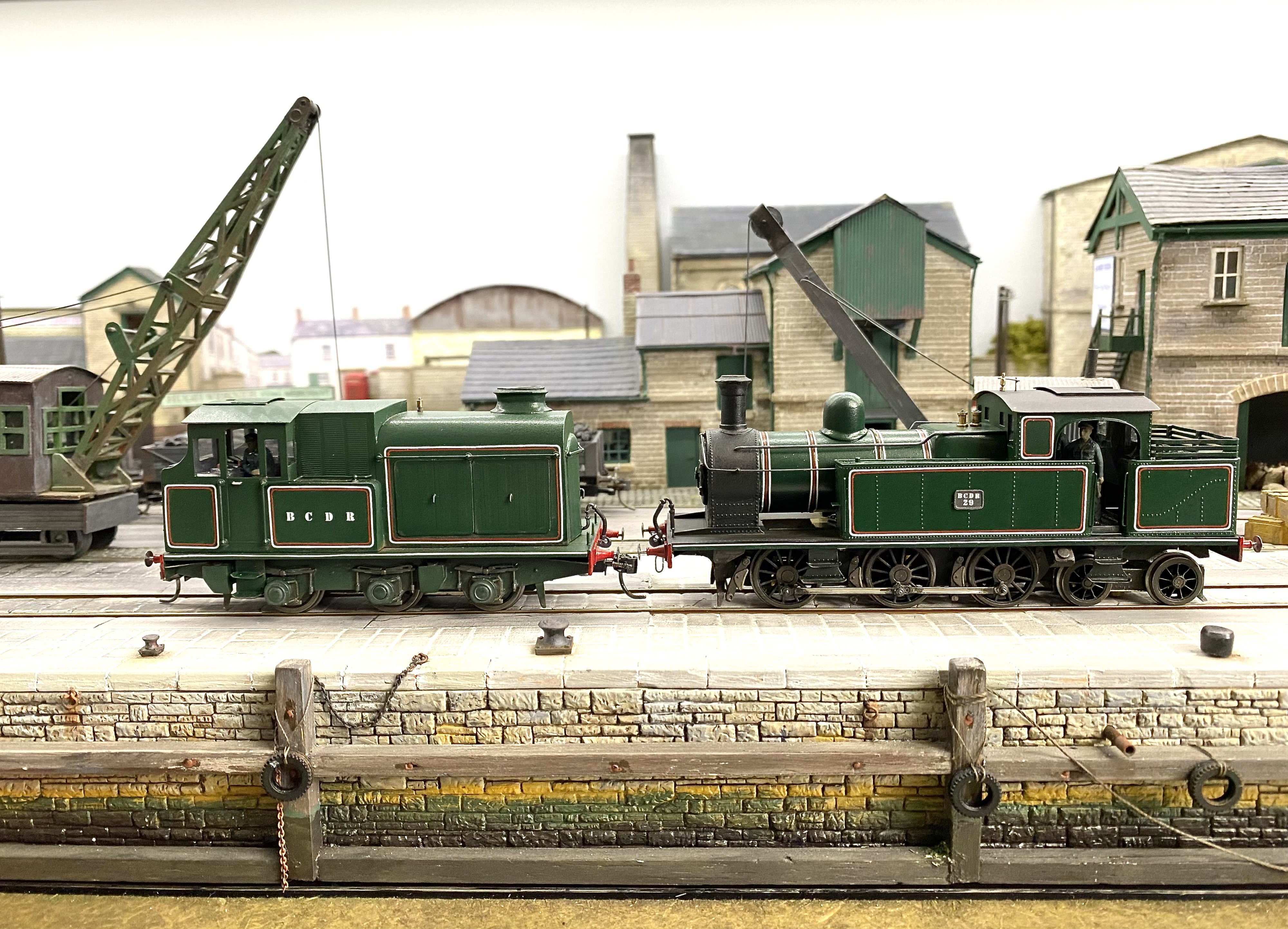
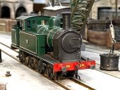
The Bangor Show was Kilmore's exhibition debut so there was a degree of apprehension as I packed the bits into the car on Friday evening. It all fitted, which was a good start, survived the journey to the venue (in truth 4 minutes drive from my house) and behaved itself all weekend. A few sulking locos over the two days but no disasters. It's the most prolonged running session most of them have ever had so I was relieved and well pleased by the end of Sunday. One thing that hadn't occurred to me prior to exhibiting was that with 7 locos all in the same livery, distinguishing one from another was sometimes quite difficult. There were occasions when no amount of throttle would increase the speed of the loco were thought we were driving. Meanwhile the loco we were actually controlling was spinning its wheels against the stops in the fiddle yard. Great show so thank you to the North Down Model Railway Society. A great chance also to meet and talk to friends old and new. I got to meet at least two folk who remembered riding on the BCDR as very young children and one whose ancestor worked on Diesel No2. Many thanks to everyone for all the positive comments on the layout and the stock. Kilmore has attracted a number of invitations for future exhibitions so all being well, we'll get it out there again soon. Thank you to Kieran Lagan for Loco Superintendent/Driving duties across the two days and to Patrick Davey for photography and heavy lifting on Sunday. A few more pics here to add to Patrick's excellent coverage above. Alan Some very fine wagons from Kieran's collection. BCDR fish vans scratch built by Gareth Brennan. Apparently when the fish traffic petered out the BCDR used the vans for moving bread. Can't imagine what it tasted like. Two diesels built by Harland & Wolff compare notes. No 28 in UTA livery is another of Gareth's creations. 0-6-4T No 29, the 'dockside shunter' does its stuff while 2-4-2T No 7 passes with a pickup goods bound for Newcastle. IMG_4663.MOV

- 176 replies
-
- 17
-

-

-
Some pics from day one at the Bangor Model Show
- 23 replies
-
- 12
-
-
Absolutely the right place for them!
-
That's very frustrating David. Getting a match between rods and wheelbase is the key to good running but errors can creep in so easily and it's very easy to end up going round in circles trying to sort them. You'll get there eventually I know. Keep at it. It's going to be a great model.
-

Another DCC Dilemma......
Tullygrainey replied to Patrick Davey's question in DCC, Electrics and Electronics
Out of interest, what have you replaced it with? -
This is looking great already David. If you nail the general look of the thing, which I think you have, a few missing spokes will be neither here nor there, nor will anyone notice! Names... picking up the Midsummer Night's Dream theme, Oberon? Titania?
-
Now that is innovative! Calls for a delicate touch with the iron I'd say.
-
Ah Darren, don't give up. If we're honest, we've all binned our first, second or even third attempts at kit building. Have another crack at it. It can be a steep learning curve but It does get easier the more you do it and the satisfaction when it goes well makes all the burnt fingers and bad language worthwhile
-
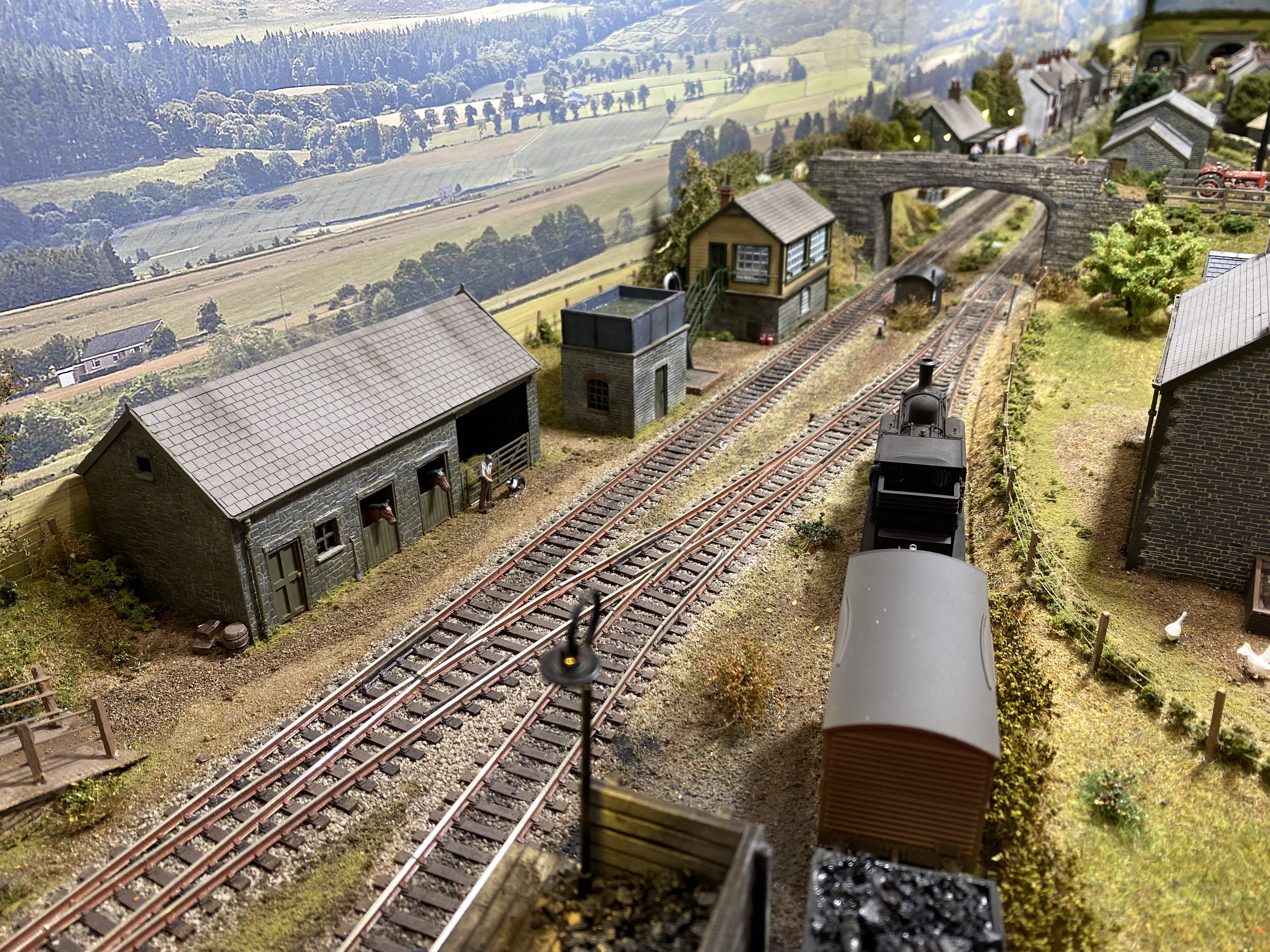
That is stunning! Totally convincing landscape modelling and a seamless transition into the photographic back scene. Wonderful.
-
Cellulose thinners will dissolve most paints, including the paint on the handle of the brush. Brush Magic from Deluxe Materials is my go-to for restoring brushes. Very effective but pricy.
-
"Voiding the Warranty" - Mol's experiments in 21mm gauge
Tullygrainey replied to Mol_PMB's topic in Irish Models
Don't they look well! Lovely work. -
Ye daren't turn yer back for a minute these days. They'd have the eye outa yer head, some of them. It's why we've got a tarpaulin over the load now. Oh, yeah, and the keys aren't in the lorry...
-
That's a very neat arrangement for the pickups David, with the copper clad out of the way on the inside of the frames. Never occurred to me to do that, though it might be a tight squeeze in the smaller scale. My copper clad bits often end up on the outside of the frames where they need to be camouflaged with paint.
-
Looks completely at home there. It looked really well in raw plastic but it's come alive now you've painted it David. Absolutely catches the essence of the thing.
-
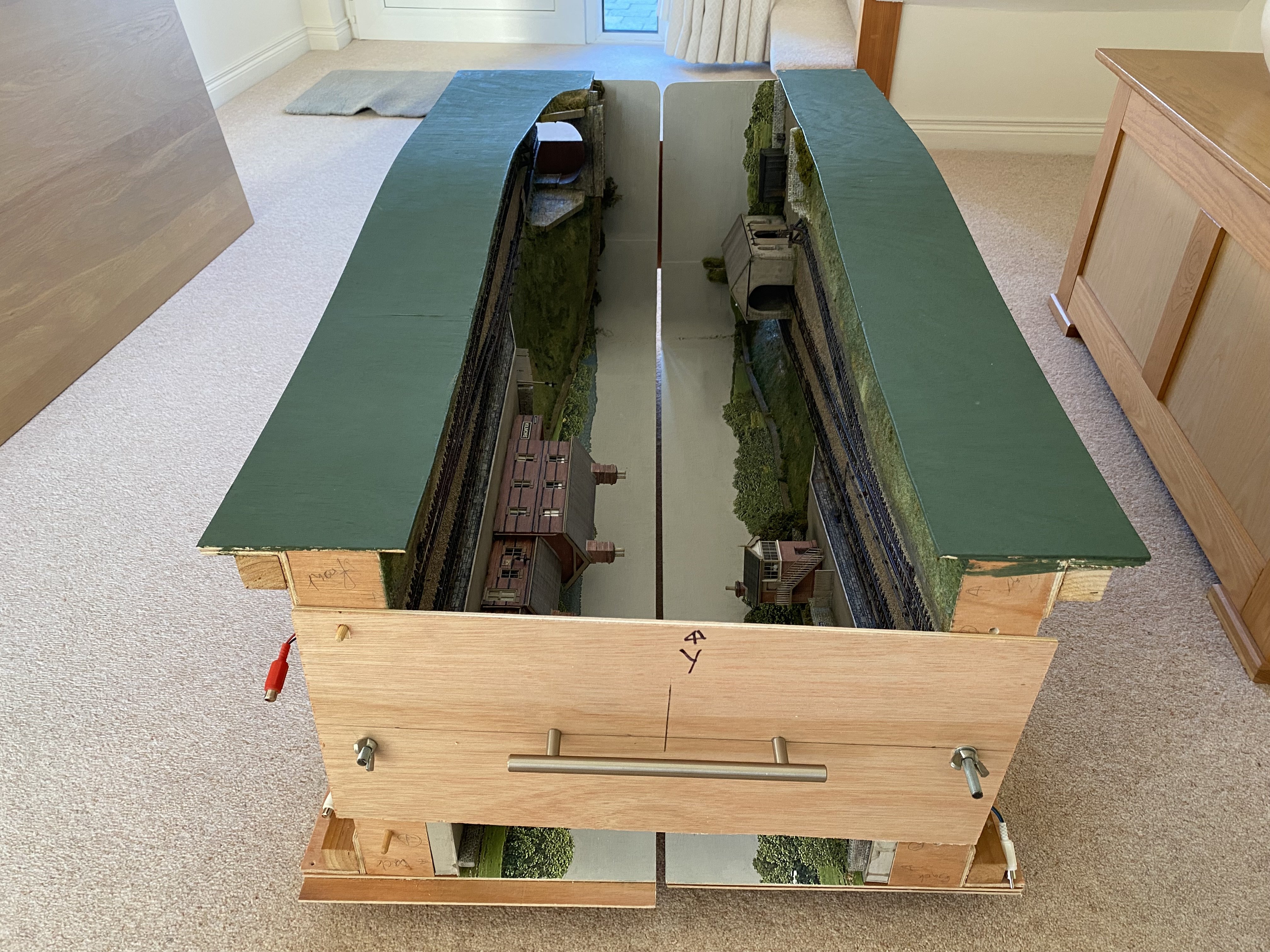
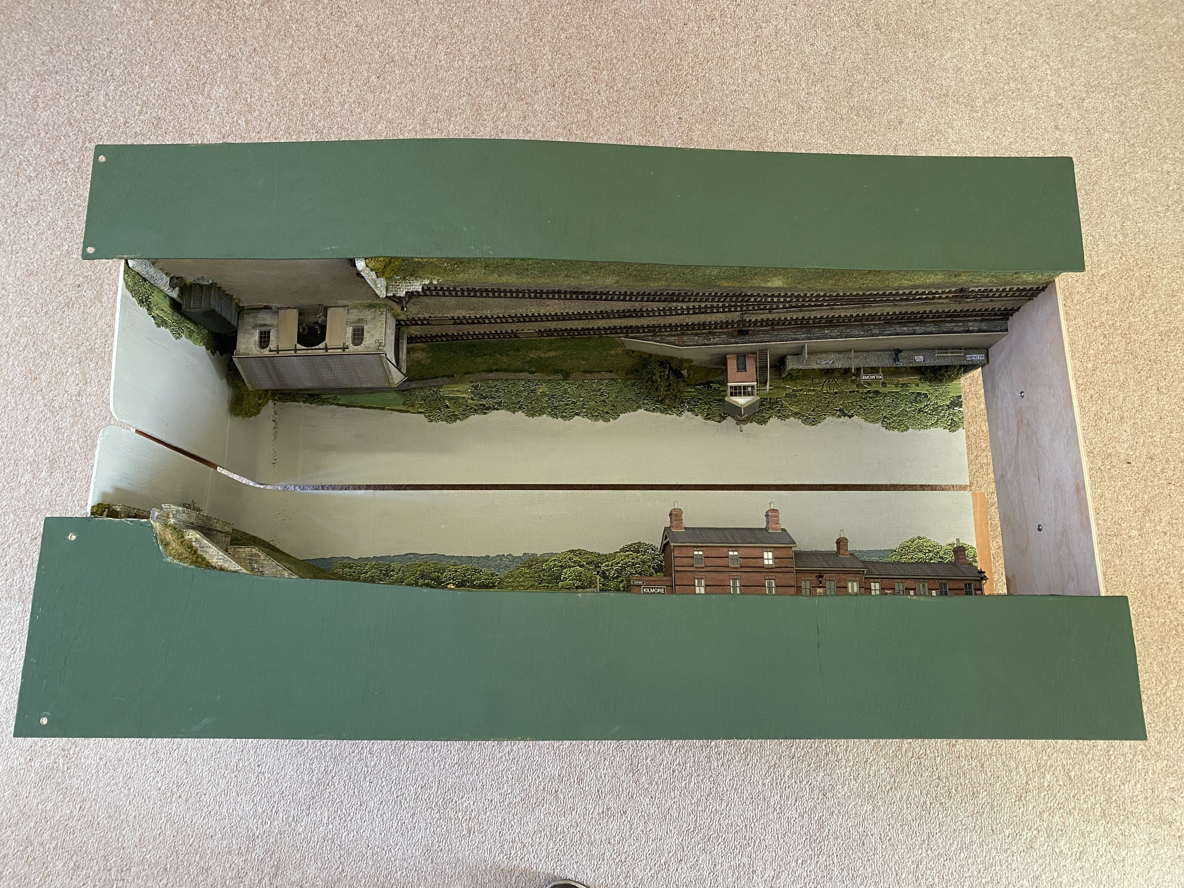
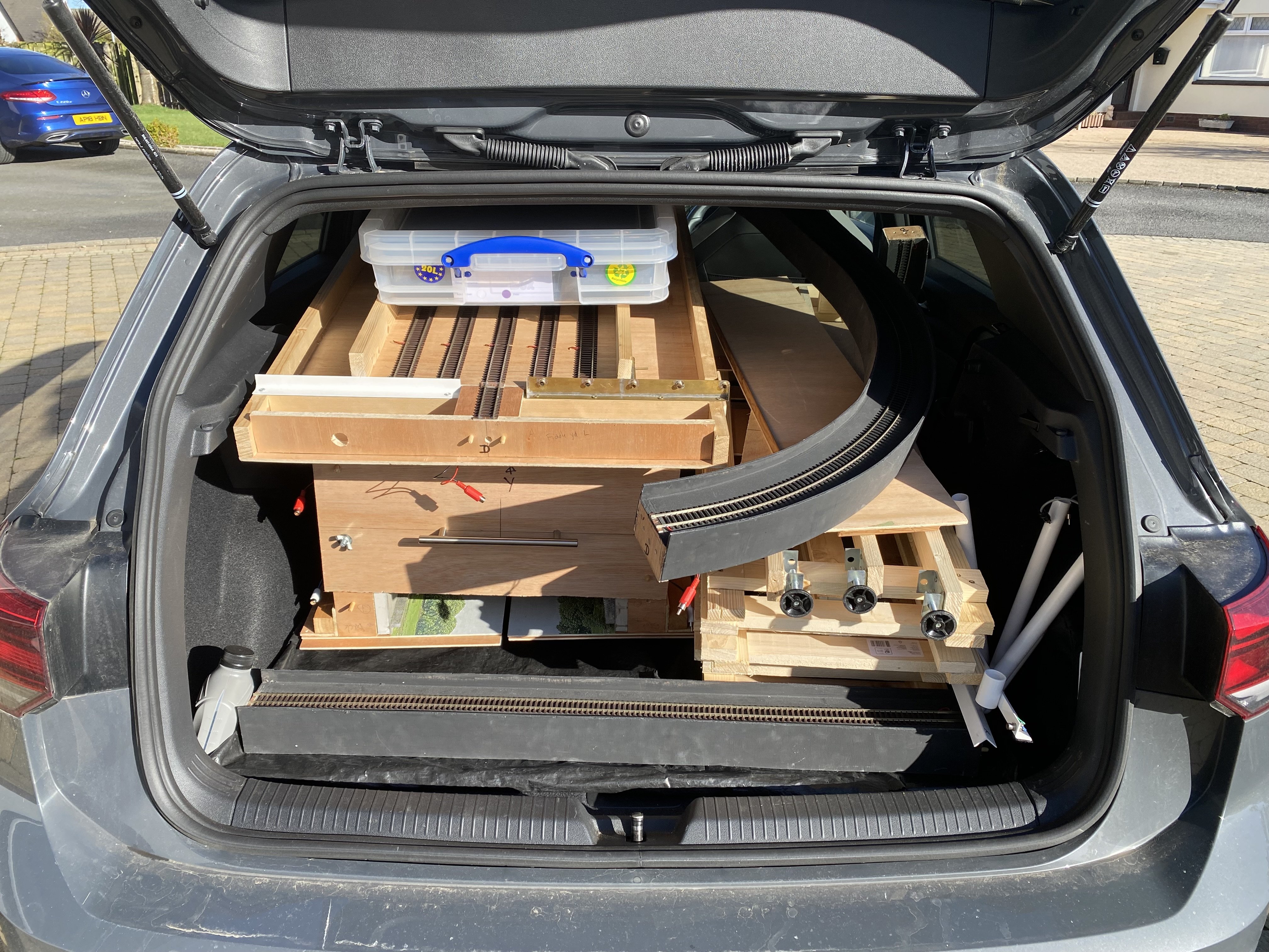
The first rain-free sunny day in ages so a dry run at packing up Kilmore for transport. And yes!! It fits in the car. Phew! And I think I do as well. Alan
- 176 replies
-
- 11
-
-
-
The long-thought-lost colour photograph of a County Down engine Nice one Patrick.
-
Just brilliant. Love it!
-
That’s an awesome feat of engineering. Wonderful!
-
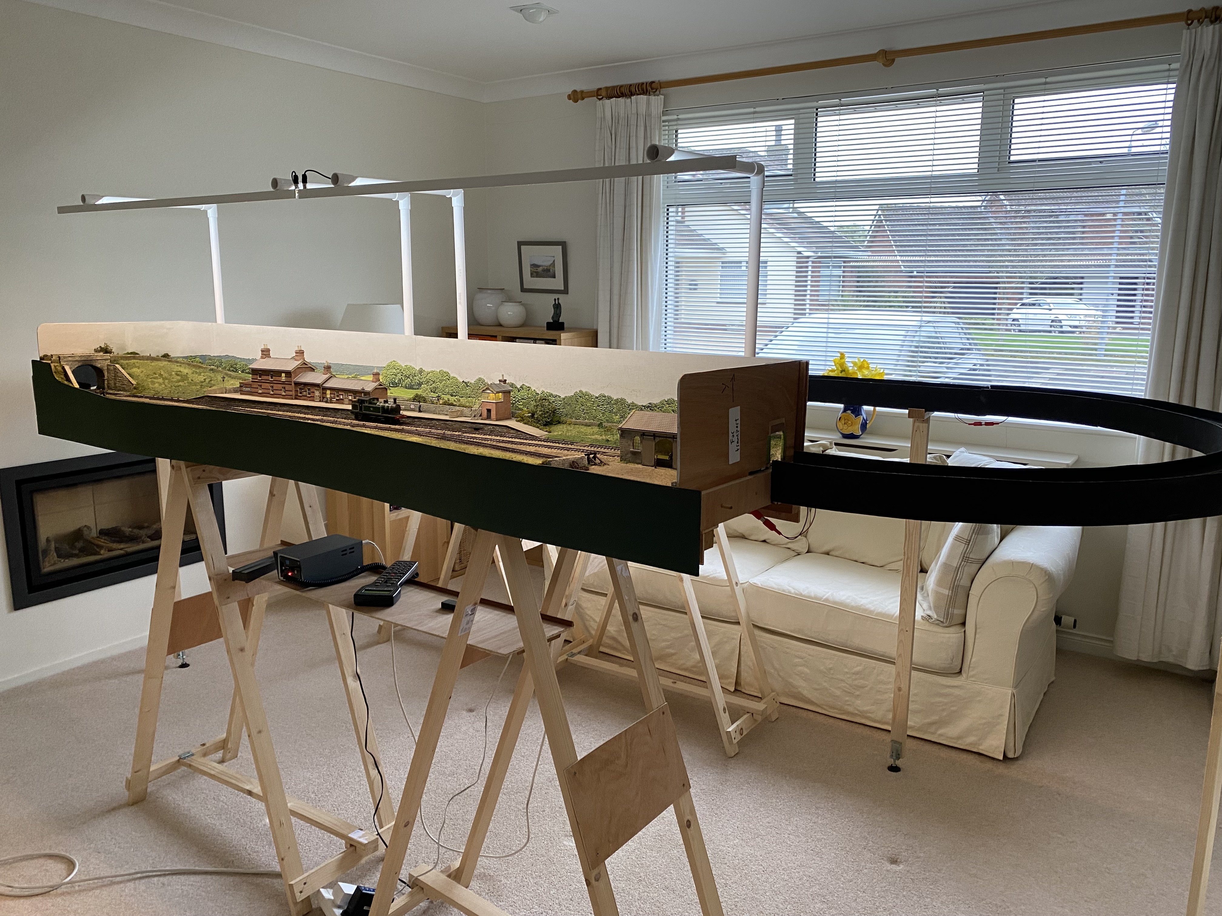
Kilmore is booked for the North Down Model Show at Bangor Grammar School, 28 & 29 March 2026 so there's a list of things that still need doing if we're to get it there. By moving some furniture out of the front room I made space to set the layout up in its entirety so I could do some debugging. And heck was it needed! Dead locos, derailments, dodgy track alignment and duff soldering among other things but the snag list is getting shorter and I was able to just watch trains going round for a change. Hope to see some of you in Bangor at the end of the month. Here's hoping this whole caboodle fits in the car Kilmore.mov Alan
- 176 replies
-
- 18
-
-
-
Nice to see this one back on the bench. I've just been re-reading the March 2024 posts where you started on it.
-
"Voiding the Warranty" - Mol's experiments in 21mm gauge
Tullygrainey replied to Mol_PMB's topic in Irish Models
Exquisite work Paul. Those look spot-on, and so neat. I'm battering away at another BCDR 6 wheeler at the moment so I have some inkling of what's involved in producing these things. Do you use colourless solder? I can't see any -
... and what sort of a loco is that on the poster!
-
"Voiding the Warranty" - Mol's experiments in 21mm gauge
Tullygrainey replied to Mol_PMB's topic in Irish Models
Lovely subtle weathering on A11 -
Lovely images. Really convincing. Are you sure it's lambs you hearing? I'm nearly certain those are cows