.png.c363cdf5c3fb7955cd92a55eb6dbbae0.png)
Tullygrainey
-
Posts
1,175 -
Joined
-
Last visited
-
Days Won
60
Content Type
Profiles
Forums
Events
Gallery
Blogs
Everything posted by Tullygrainey
-
Yep, it's a solid bit of pipe left over from plumbing the Titanic. O.D. 16mm I.D. 13.5mm Length: 61mm Weight: 29 gms Tools required to fit it: An angle grinder and a very large blow lamp I reckon

-
Mick Rawlings' Build of a U Class: MRJ 279, p.141 Ballyconnell Road: MRJ 249, p.215
-
Thanks for this John. A wealth of changes over the lifetime of this particular loco class so plenty to consider before deciding on which one to model. Not surprised to discover I wasn't the first to wreck one of the n/s rods! They really are flimsy. My first instinct was to try using the original brass ones but like you, discovered they had different centres. So much for that plan. I haven't even looked at the body etches yet. I'll try getting the chassis working first. It's had a coat of paint now so wheeling up is next - the moment of truth for the remade rod.
-
TMD/SSM MGWR "W" / GSR J26 / CIE "551" 0-6-0T
Tullygrainey replied to Horsetan's topic in Photos of Models
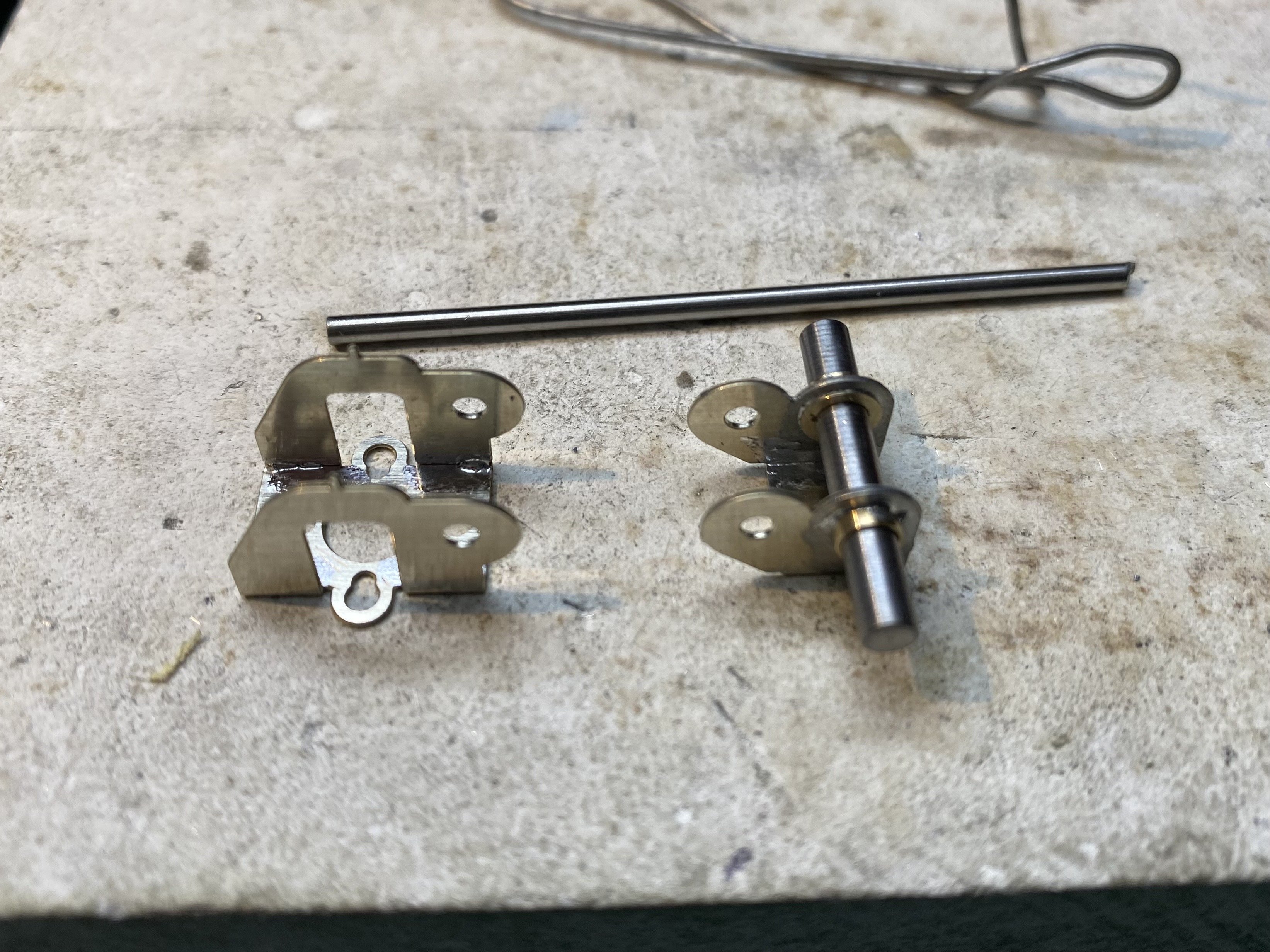
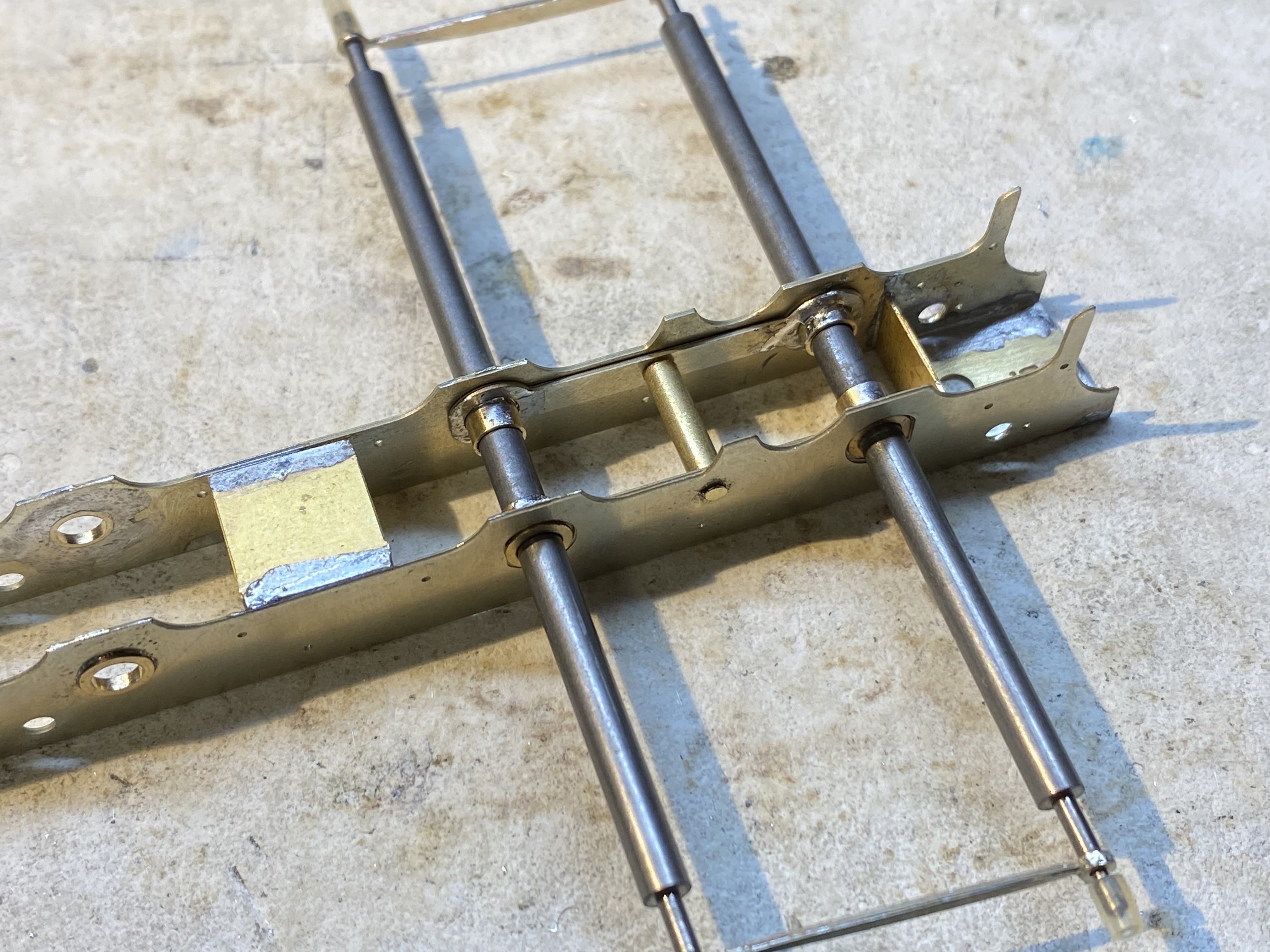
Thanks for digging this out Paul. Lots of useful stuff here. I should've known there'd be info tucked away on this forum! Mayner's comment on page one: The later n/s chassis was designed for compensated assembly using top hat brushes and equalising beams. I found that the axle holes for the rocking axles were etched oversized for the collar of a 1/8" top hat bearing. confirms something I half-suspected. The collar on the bearings are meant to bear on the outside of the frames and thus trap the equalising beams in place against the inside face. Instead they just slip through the holes and the beams stray toward the centre of the chassis. Which is why I ended up with the brass tube collar on the pivot rod.
-
Ah David, you have my sympathies. A real heart-sink moment. Hope you can get it sorted.
-
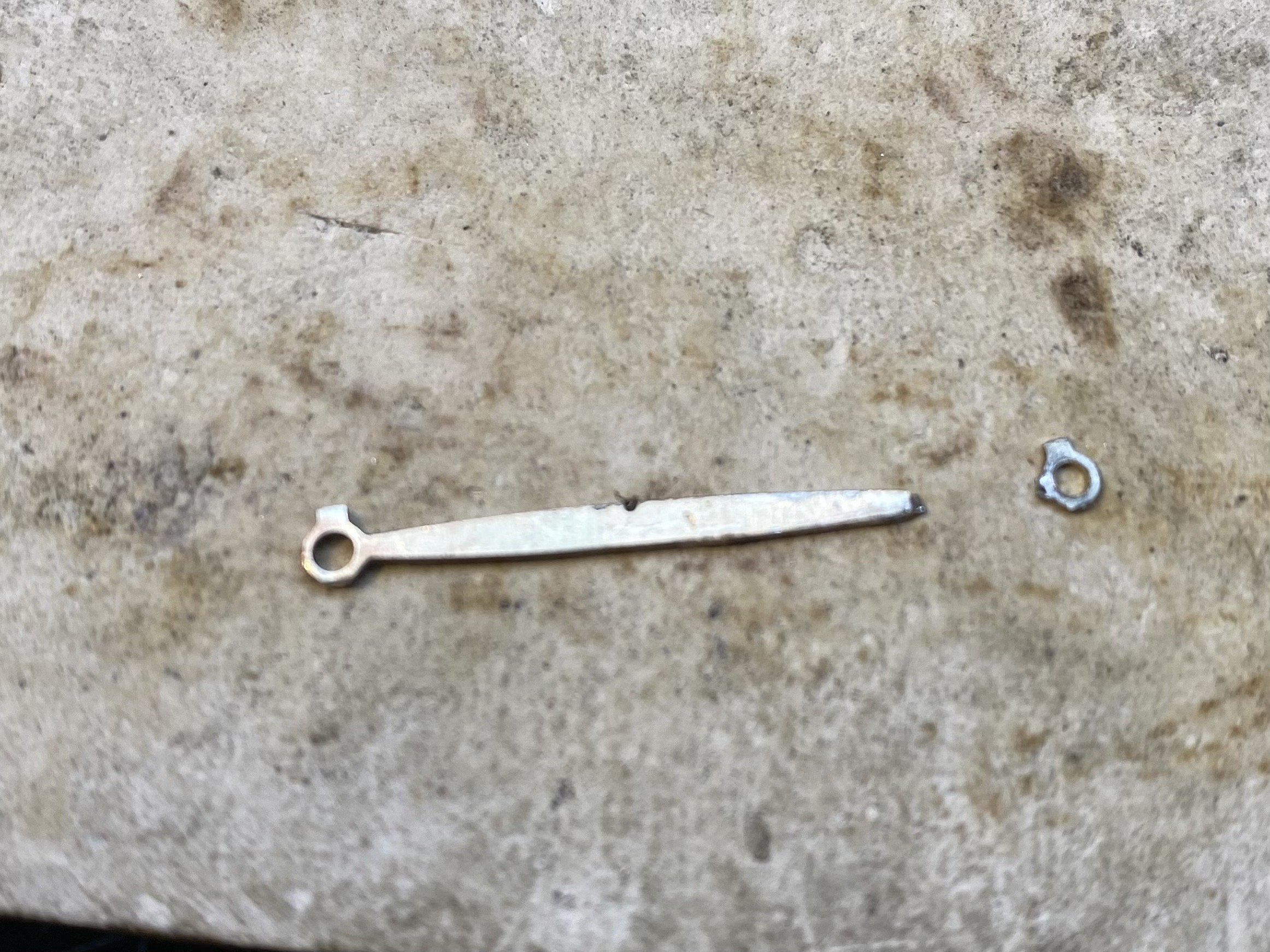
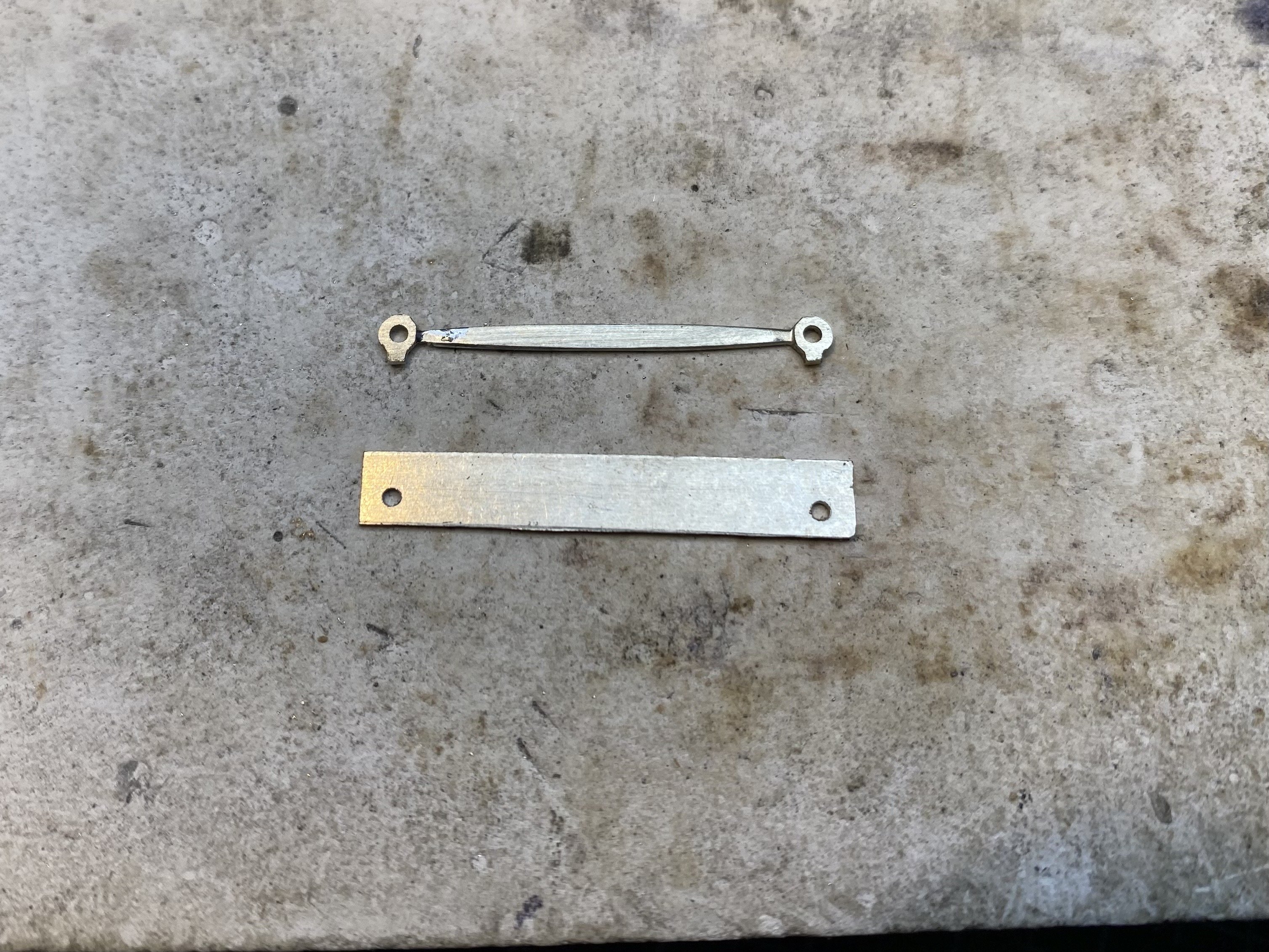
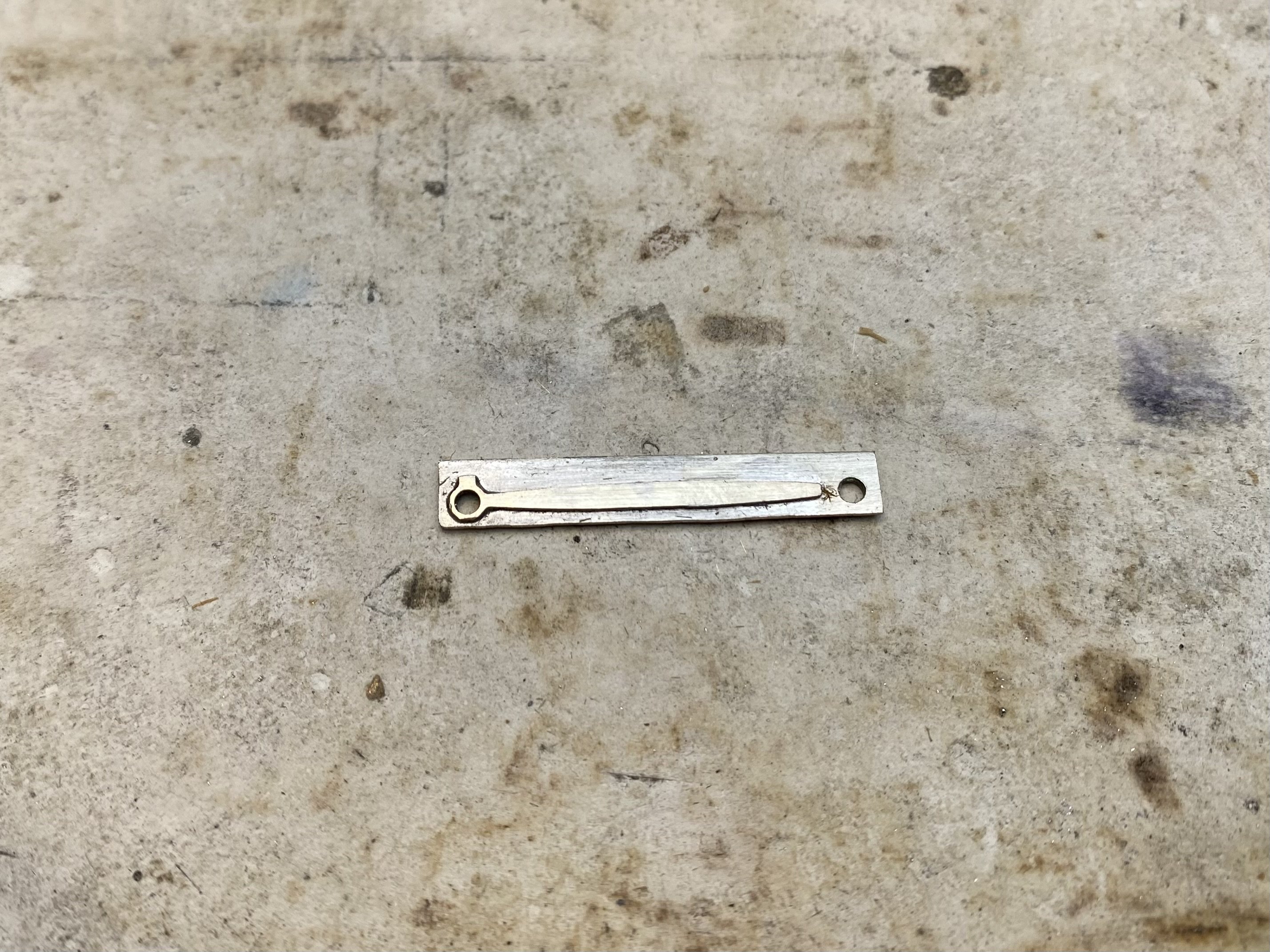
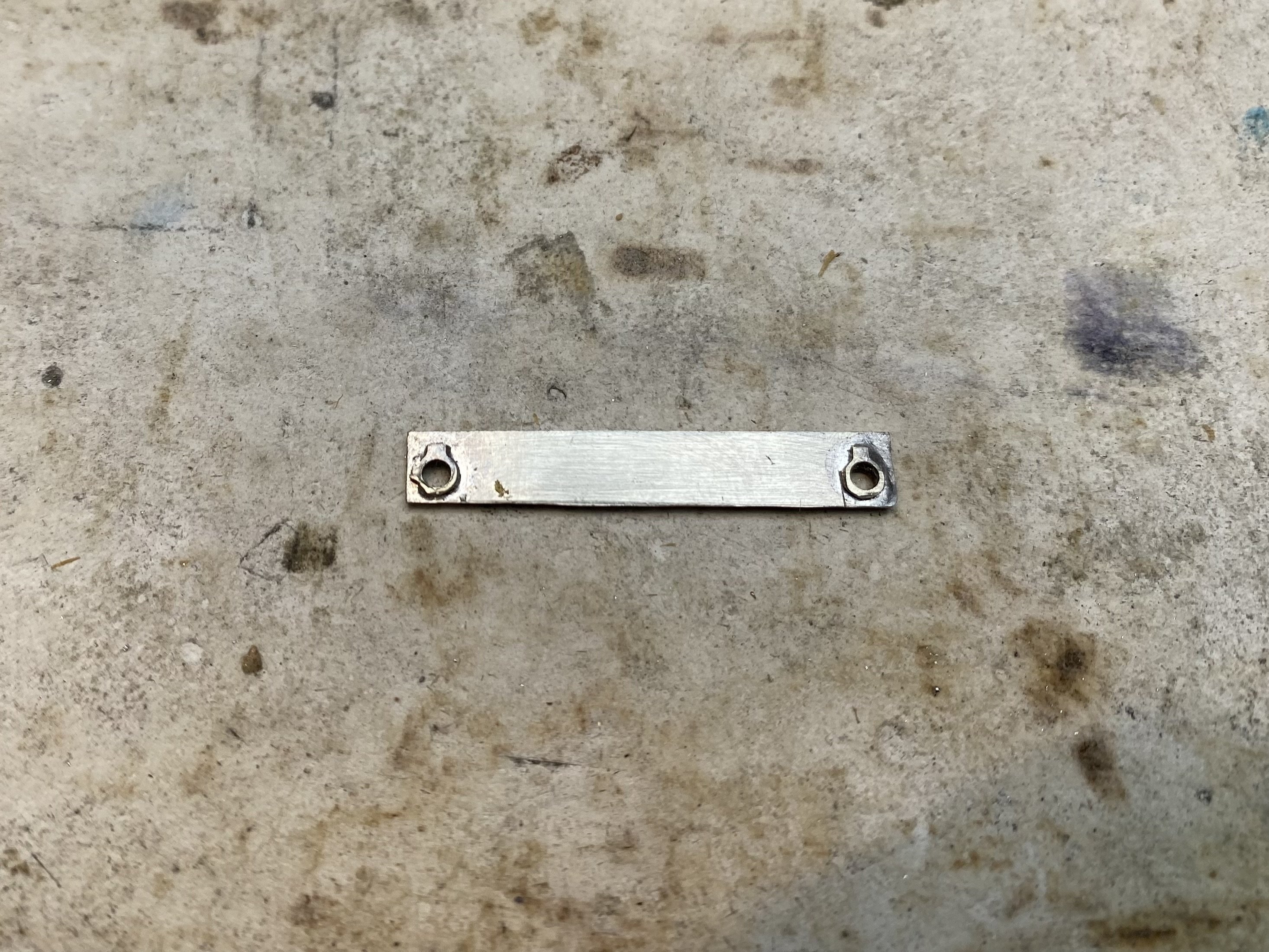
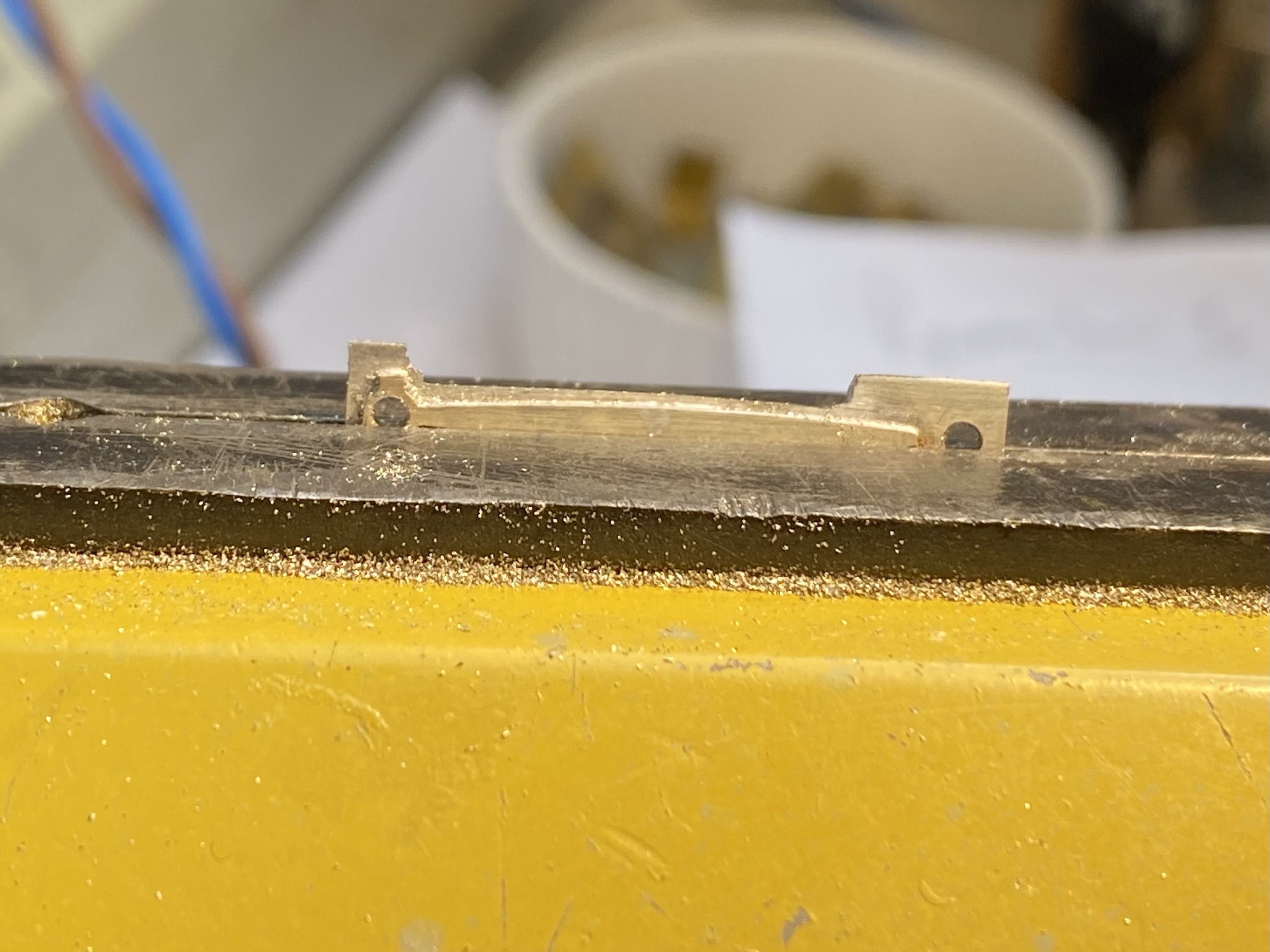
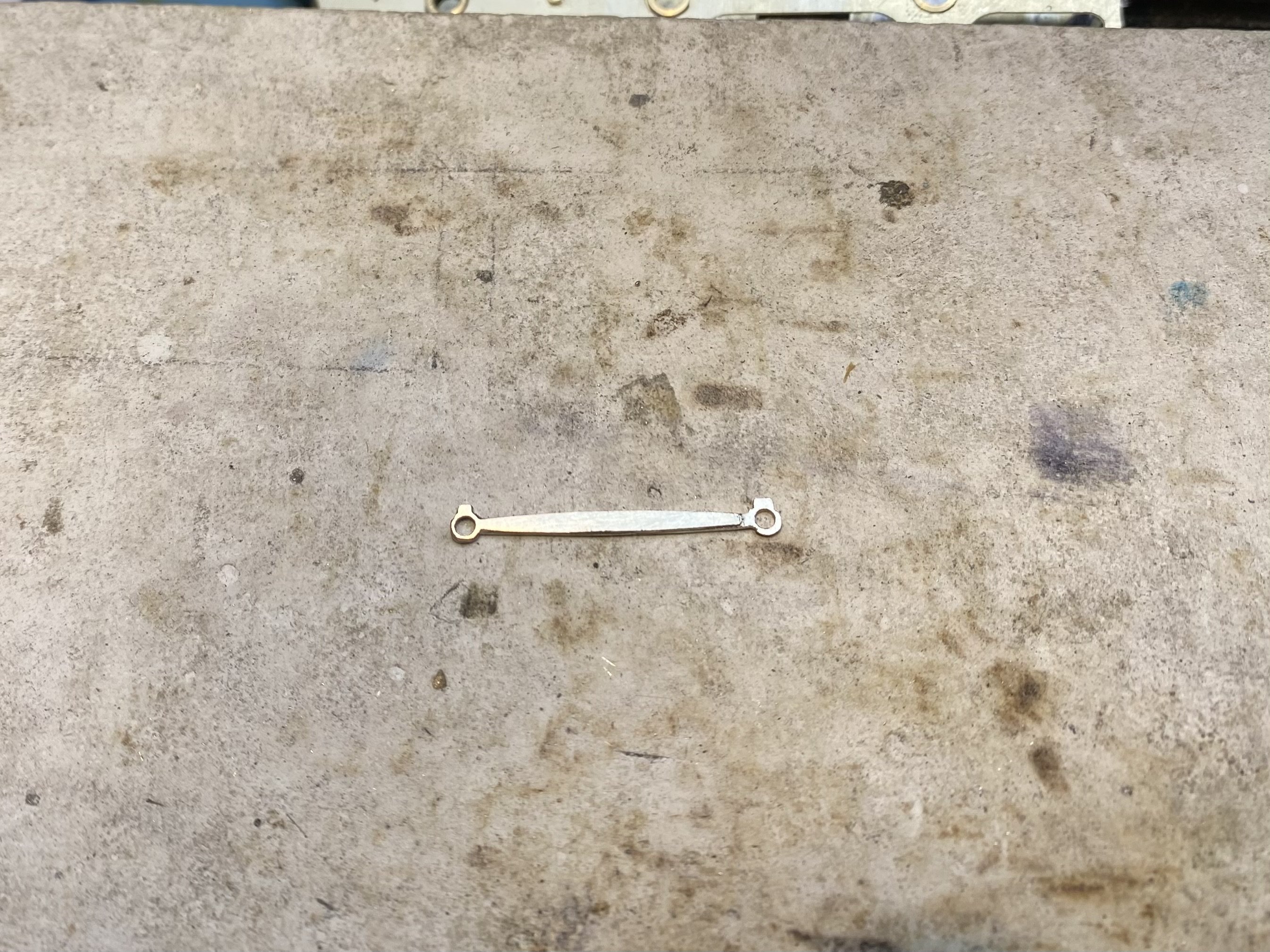
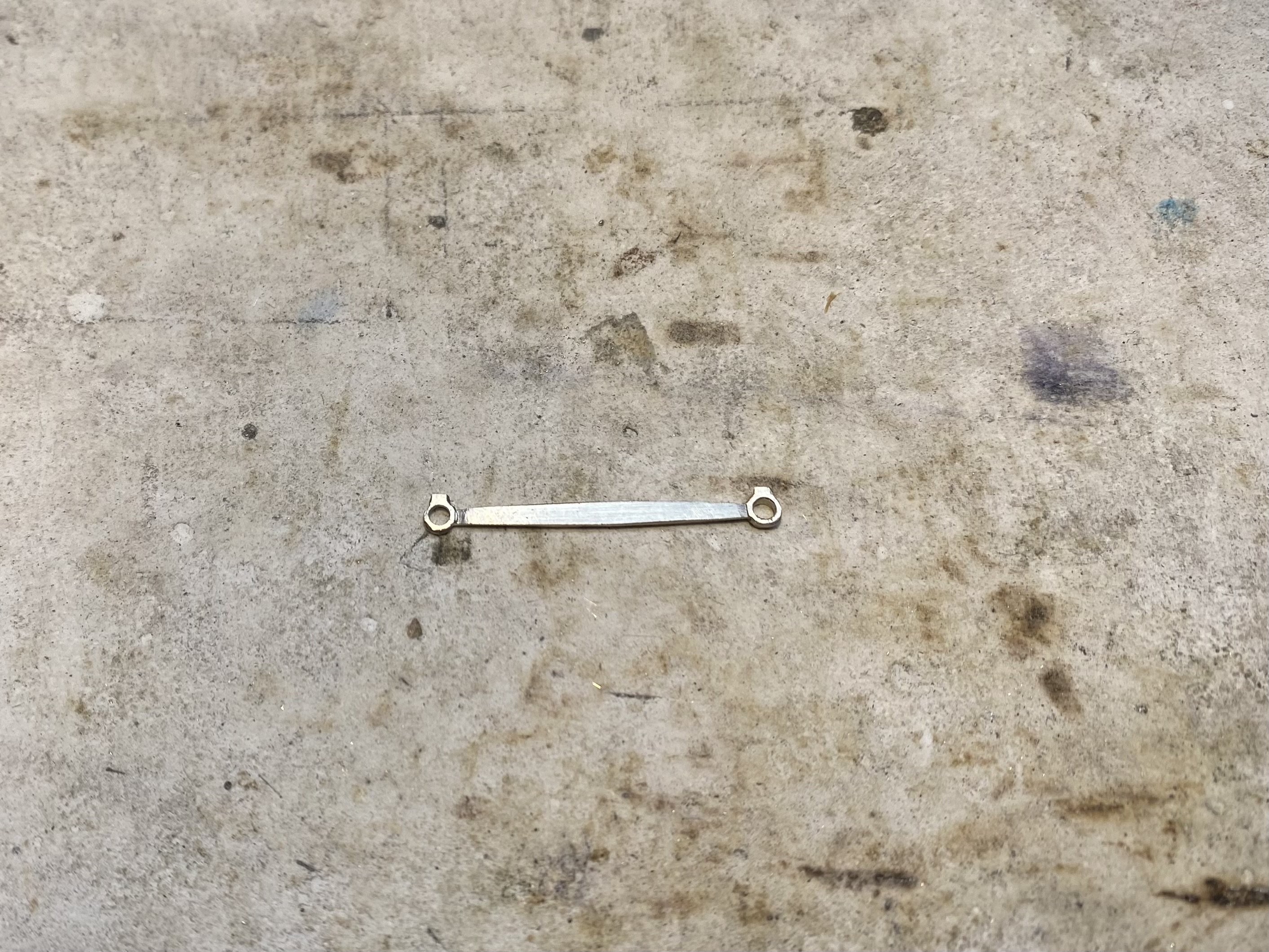
The Case of the Crippled Coupling Rod Each coupling rod assembly for the E Class/J26 is made up from two sections which hinge by overlapping on the centre axle. Each section is a lamination with two layers soldered together. At the overlap, each rod has only a single layer. With some half-etching to create bosses, the bits are pretty flimsy. Once soldered up the holes were reamed lightly to fit onto the jig axles (around 1.5mm diameter). All good so far. The kit came with Markits type threaded crankpins which take threaded crankpin bushes. This requires the holes in the rods to be reamed out to 2mm diameter and this is when disaster struck. A moment's lack of concentration, the reamer grabbed and the end of the rod twisted off. Unseemly language was used. In abundance. No way of soldering this back on! The solution, after I'd calmed down, was to use the equivalent rod from the other side (still with 1.5mm holes) as a jig to drill two 1.5mm holes the right distance apart in a strip of 16 thou nickel silver using the pillar drill. Onto this I soldered salvaged bits from the broken rod - the short rear piece on one side and two bosses on the other thus: Rear face... Front face... After reaming the holes to 2mm, the rough blank was filed to shape using the bit of original rod as a guide. The finished product will do the job, I hope. It's certainly more robust than the original. Rear face with the single thickness overlap at one end... Front face... Two plus hours just to get back where I started. Ah well, all grist to the mill Onward and upward, Alan
- 860 replies
-
- 14
-

-

-
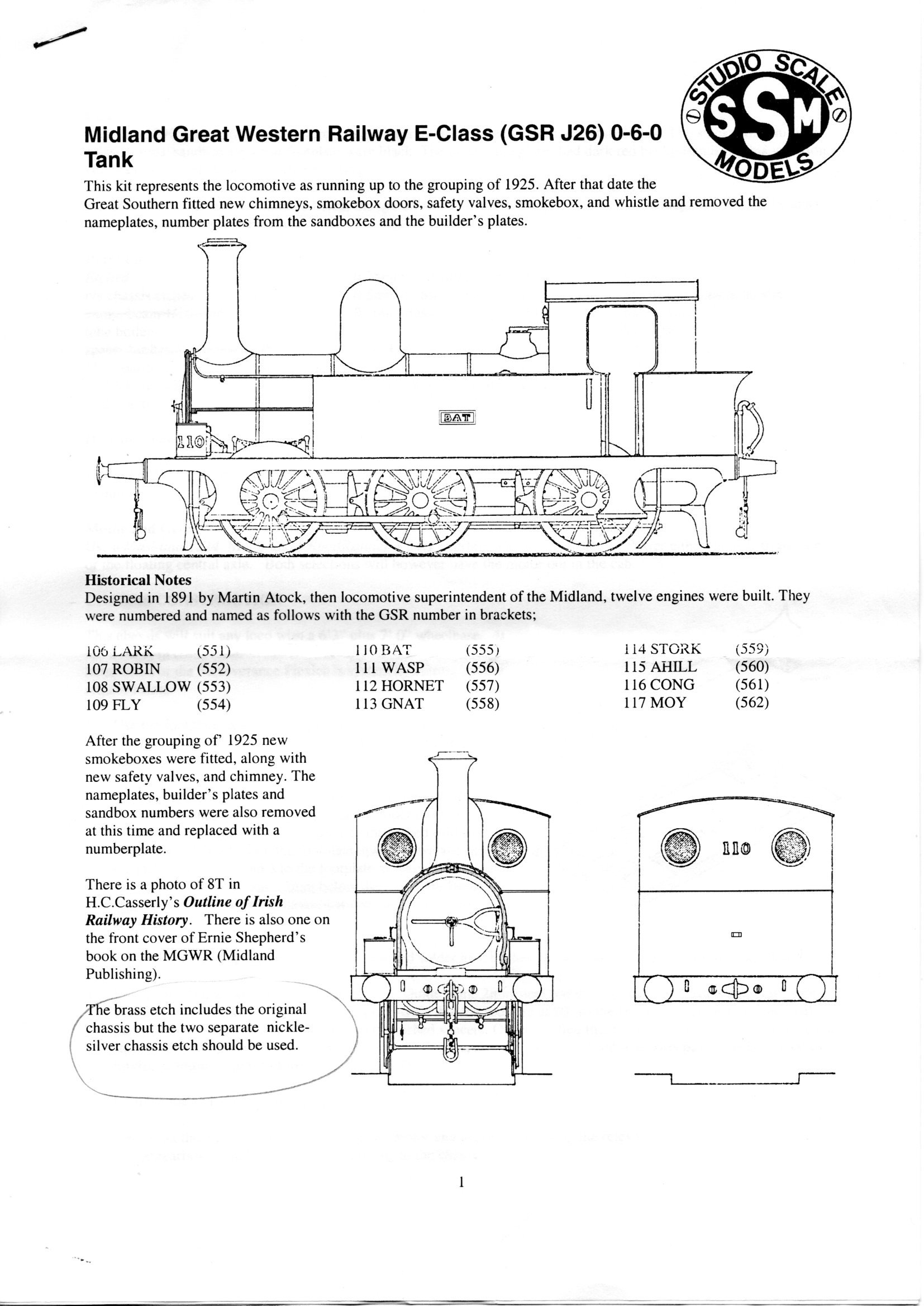
16.5mm Paul and I'll need to consult Kieran about the target prototype. The kit is designed to be built in pre-grouping E Class form but Kieran would like a later era J26 so we'll need a different chimney and safety valves as well as a few other modifications.
-
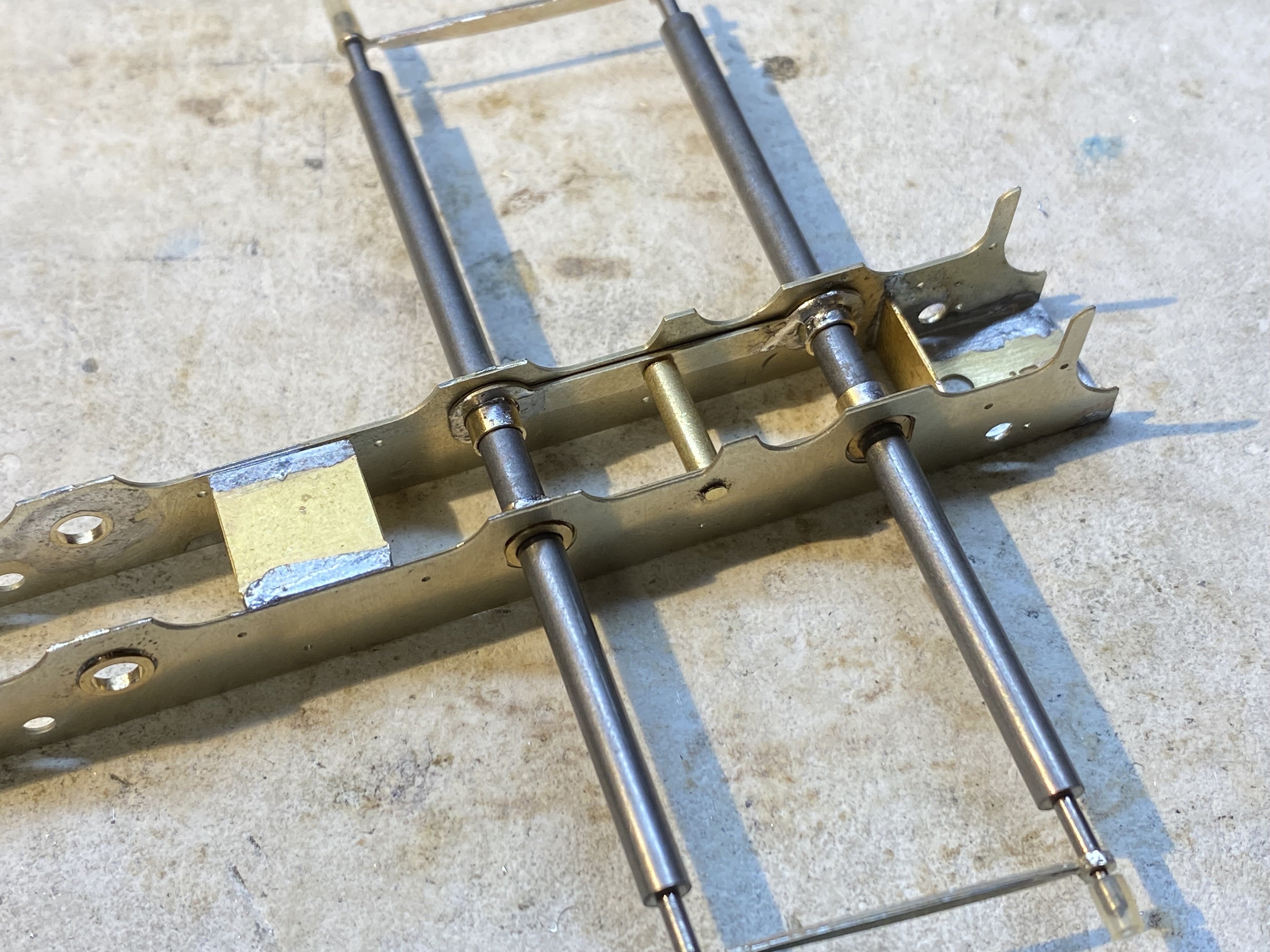
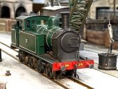
The Kirtley project (see above) got parked while waiting for gearbox parts. Those have arrived now and I'll get back to it presently but In the meantime, another loco for Kieran Lagan, a Studio Scale Models kit for an E Class/J26 which I think may have been in his to-do drawer for a while Gearbox first, and as usual the device of choice is from HIgh Level, a RoadRunner Compact+. This one is low profile and has an articulated final drive to help fit it into tight spaces. Sewing machine smooth as usual. I think this one is an earlier version because it has a brass final drive gear and the one I got recently for the Kirtley is different. IMG_4677.MOV The chassis as designed has compensation on 2 axles but rather than horn guides it has twin beams each holding 2 fixed axle bearings and each pivoting about its centre point on a rod fixed across the chassis. I convinced myself that this arrangement couldn't work because it wouldn't allow the axles to tilt - essential for keeping both the wheels in contact with the rails at all times - and in theory I think this is true. If one wheel rises, it will take its mate at the other end of the axle with it. However in practice, the 'give' in the system such as running clearance in the bearings and a bit of slack at the pivots permits enough tilt to do the business. The actual job of installing these was fiddly and the instructions are brief(!) I found that the beams, which are meant to sit against the inside of the chassis frames, tended to stray towards the middle so I've added a bit of brass tube over the rod on which they pivot, just wide enough to fit between the beams and keep them in their proper place. The instructions suggest installing the beams and only then making up the coupling rods. To my mind, that's putting enormous faith in the accuracy of the etch AND the accuracy of the build given that by convention, all the holes are etched slightly undersize and need to be reamed out. There's margin for error there! I did it the other way round in order to use the rods as jigs and be sure of getting the axle bearings in exactly the right place. Belt and braces I've since had a bit of a mishap while reaming out the rods for crankpin bushes but that's a story for another day. It's way past my bedtime. More soon, Alan
- 860 replies
-
- 11
-
-
Many thanks Damien. Good to see you again. Best of luck with the current project!
-
All three are appealing in their way. I like the sepia one - very 19th century - but it looks older than the loco given that, although No6 was built in 1894, the model represents it after its 1943 rebuild when it emerged looking quite different from its original form.
-
Fish fans? Is that to keep them cool now the oceans are warming up?
-
Here we go. When he was making the models I’d say Gareth had to trawl the internet for good photos
-
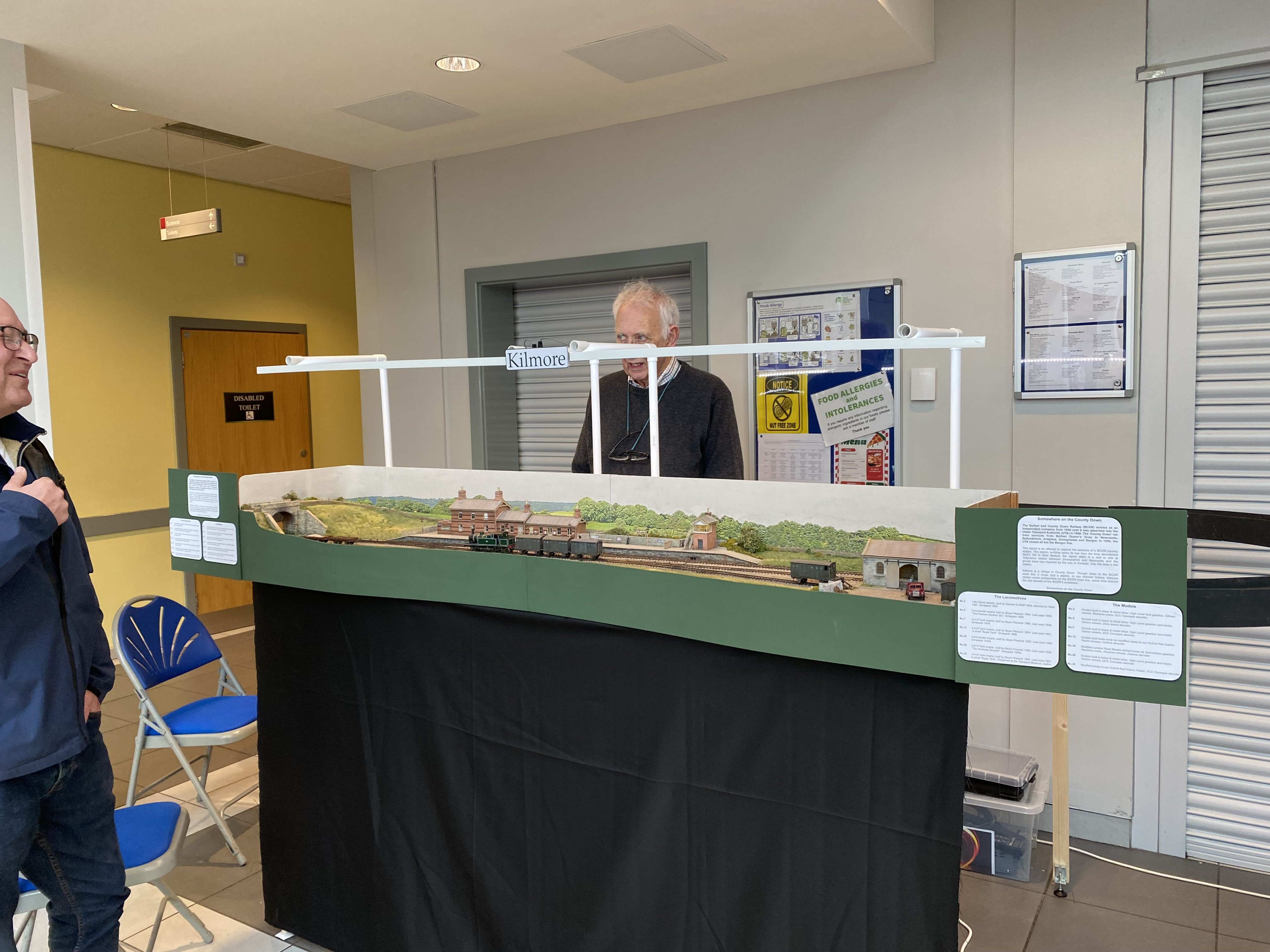
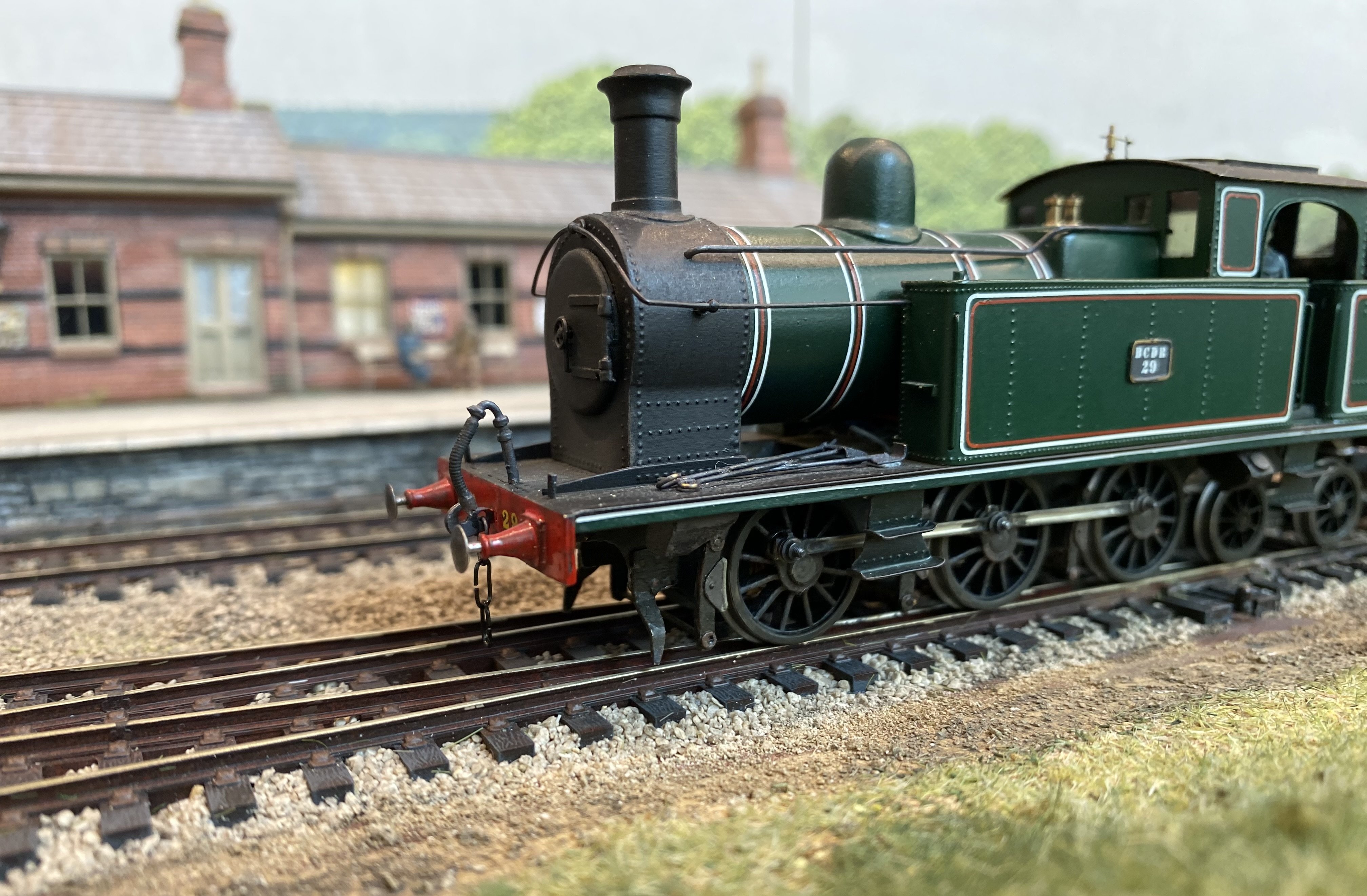
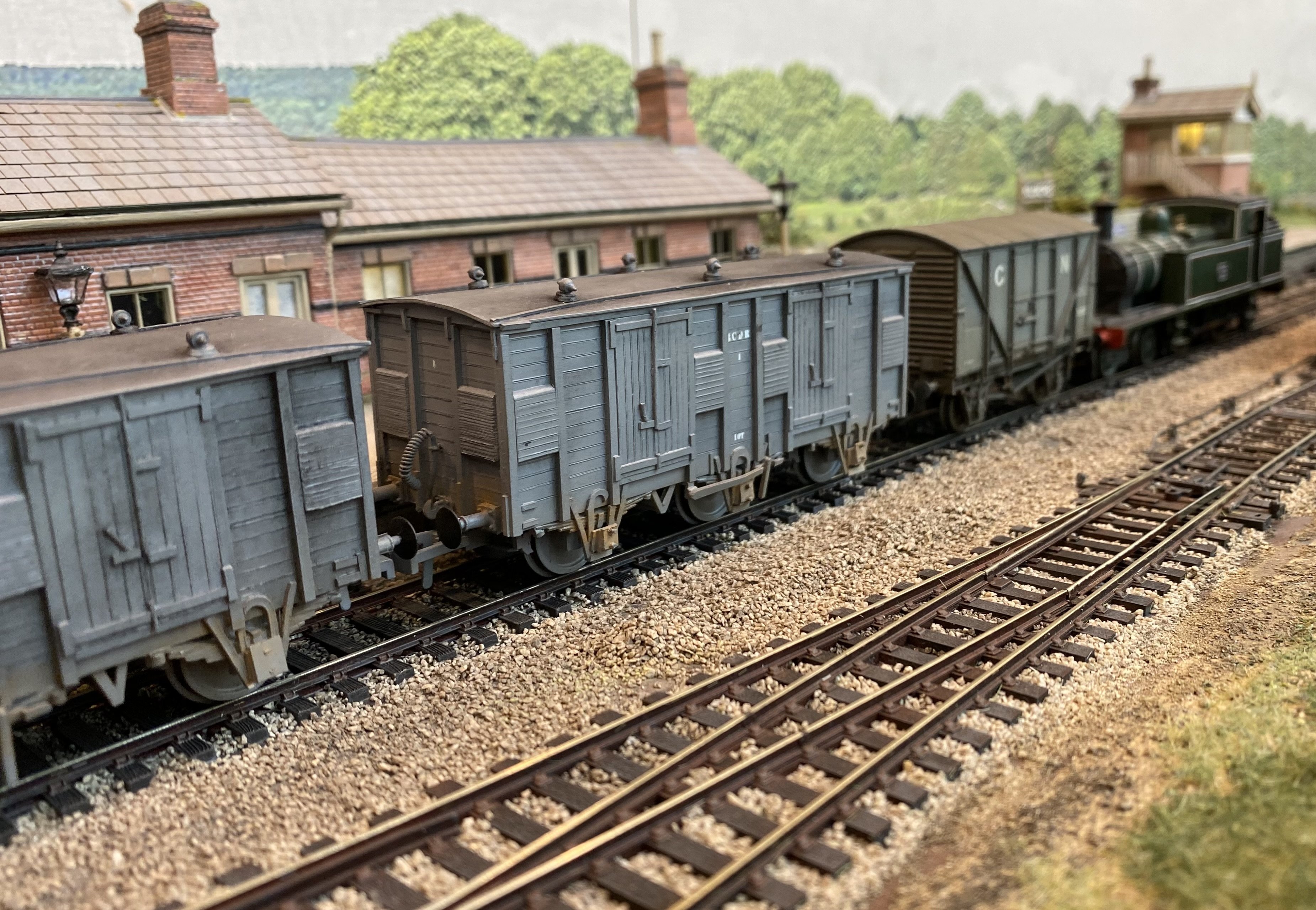
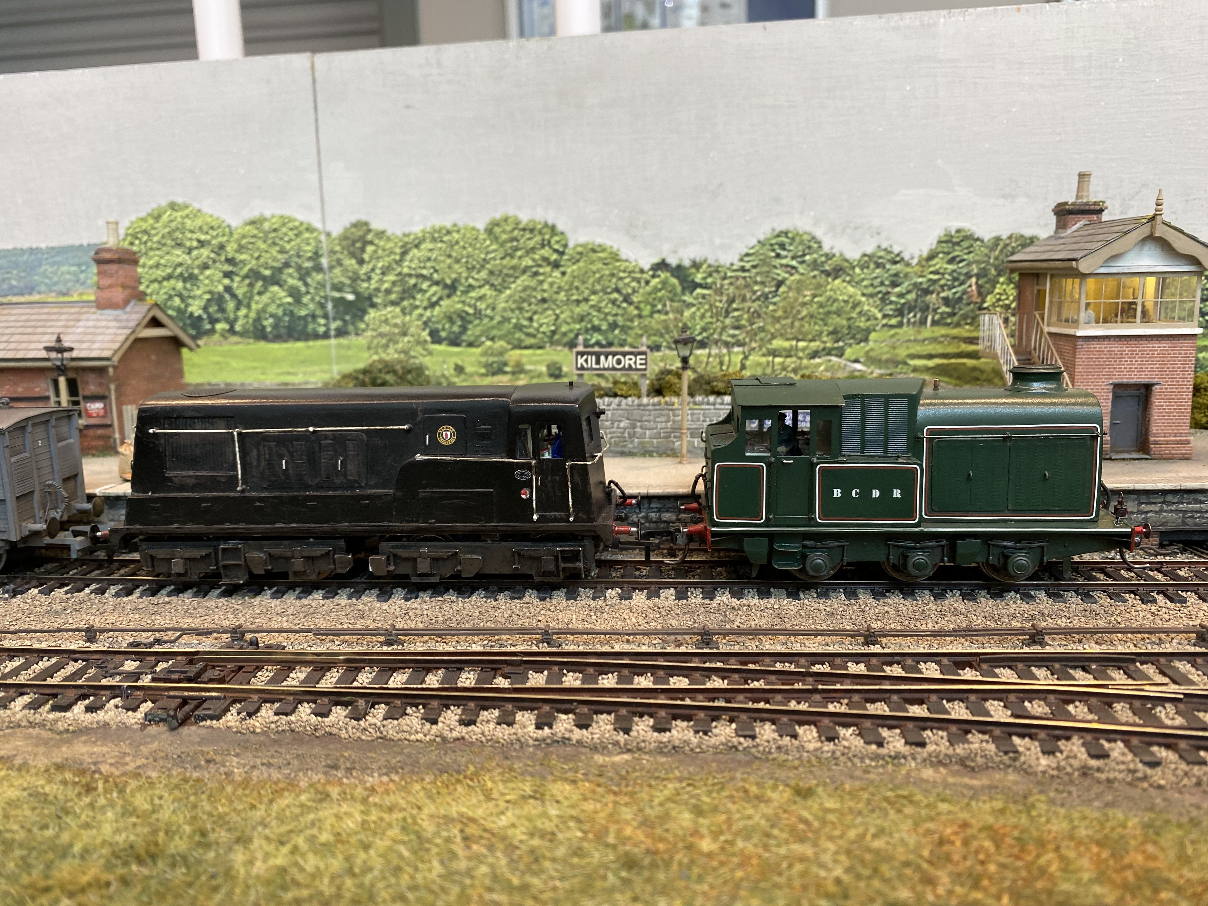
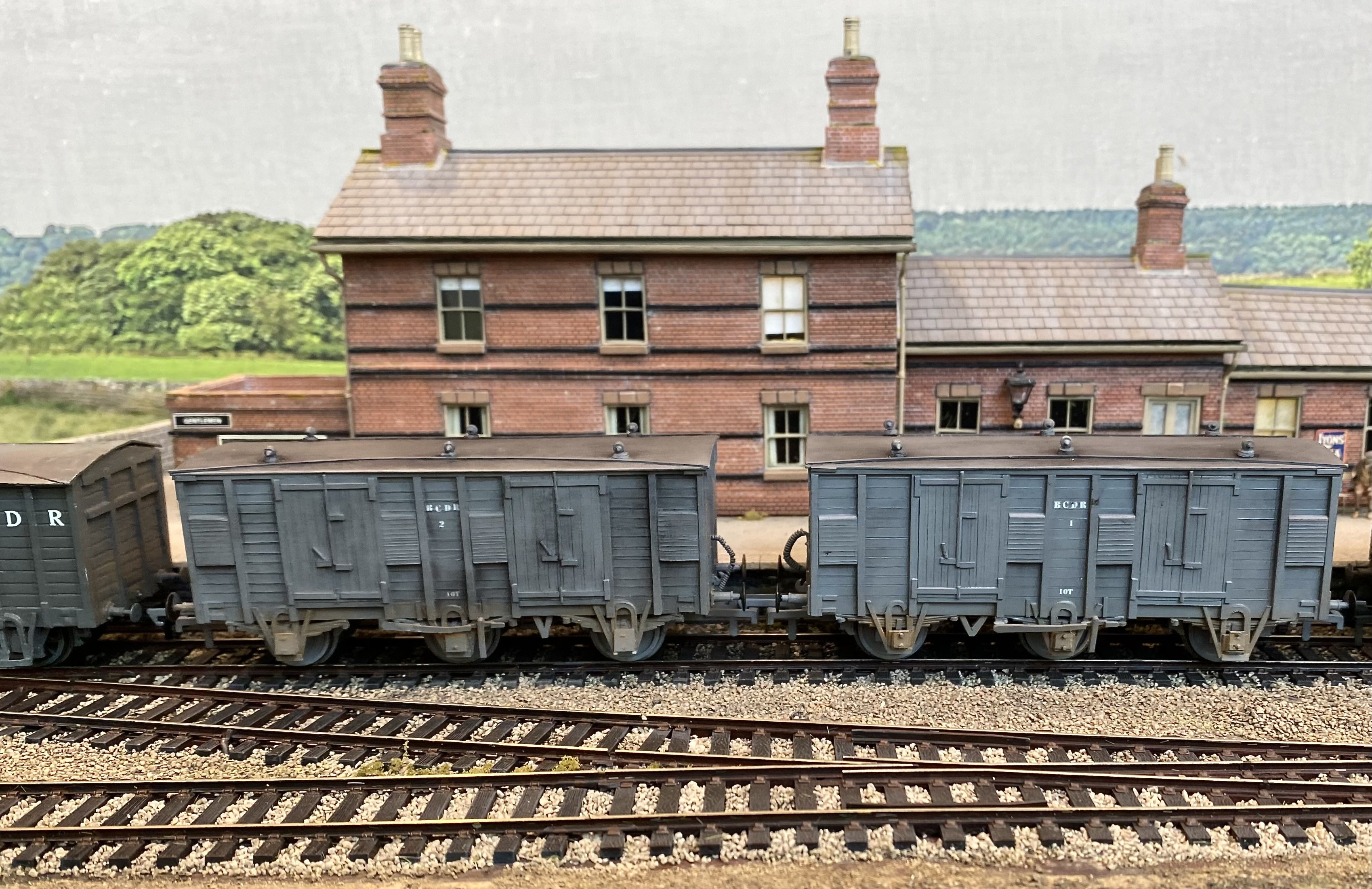
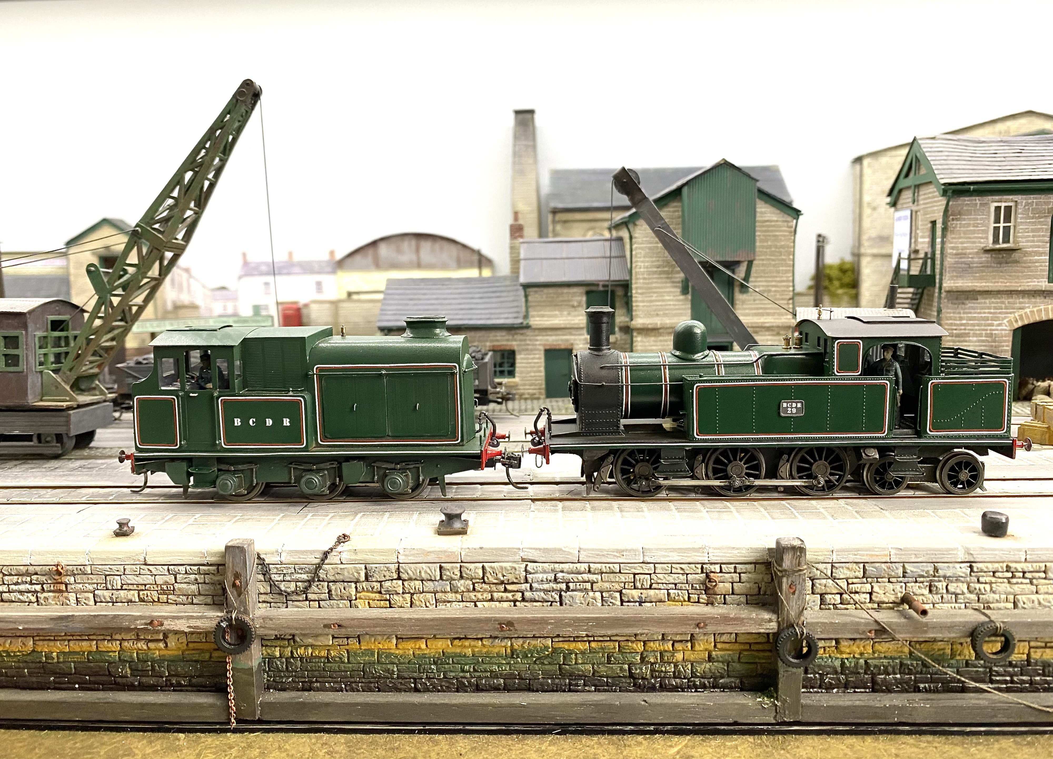
The Bangor Show was Kilmore's exhibition debut so there was a degree of apprehension as I packed the bits into the car on Friday evening. It all fitted, which was a good start, survived the journey to the venue (in truth 4 minutes drive from my house) and behaved itself all weekend. A few sulking locos over the two days but no disasters. It's the most prolonged running session most of them have ever had so I was relieved and well pleased by the end of Sunday. One thing that hadn't occurred to me prior to exhibiting was that with 7 locos all in the same livery, distinguishing one from another was sometimes quite difficult. There were occasions when no amount of throttle would increase the speed of the loco were thought we were driving. Meanwhile the loco we were actually controlling was spinning its wheels against the stops in the fiddle yard. Great show so thank you to the North Down Model Railway Society. A great chance also to meet and talk to friends old and new. I got to meet at least two folk who remembered riding on the BCDR as very young children and one whose ancestor worked on Diesel No2. Many thanks to everyone for all the positive comments on the layout and the stock. Kilmore has attracted a number of invitations for future exhibitions so all being well, we'll get it out there again soon. Thank you to Kieran Lagan for Loco Superintendent/Driving duties across the two days and to Patrick Davey for photography and heavy lifting on Sunday. A few more pics here to add to Patrick's excellent coverage above. Alan Some very fine wagons from Kieran's collection. BCDR fish vans scratch built by Gareth Brennan. Apparently when the fish traffic petered out the BCDR used the vans for moving bread. Can't imagine what it tasted like. Two diesels built by Harland & Wolff compare notes. No 28 in UTA livery is another of Gareth's creations. 0-6-4T No 29, the 'dockside shunter' does its stuff while 2-4-2T No 7 passes with a pickup goods bound for Newcastle. IMG_4663.MOV
- 180 replies
-
- 17
-
-
-
Some pics from day one at the Bangor Model Show
- 23 replies
-
- 12
-
-
Absolutely the right place for them!
-
That's very frustrating David. Getting a match between rods and wheelbase is the key to good running but errors can creep in so easily and it's very easy to end up going round in circles trying to sort them. You'll get there eventually I know. Keep at it. It's going to be a great model.
-
Another DCC Dilemma......
Tullygrainey replied to Patrick Davey's question in DCC, Electrics and Electronics
Out of interest, what have you replaced it with? -
This is looking great already David. If you nail the general look of the thing, which I think you have, a few missing spokes will be neither here nor there, nor will anyone notice! Names... picking up the Midsummer Night's Dream theme, Oberon? Titania?
-
Now that is innovative! Calls for a delicate touch with the iron I'd say.
-
Ah Darren, don't give up. If we're honest, we've all binned our first, second or even third attempts at kit building. Have another crack at it. It can be a steep learning curve but It does get easier the more you do it and the satisfaction when it goes well makes all the burnt fingers and bad language worthwhile
-
That is stunning! Totally convincing landscape modelling and a seamless transition into the photographic back scene. Wonderful.
-
Cellulose thinners will dissolve most paints, including the paint on the handle of the brush. Brush Magic from Deluxe Materials is my go-to for restoring brushes. Very effective but pricy.
-
"Voiding the Warranty" - Mol's experiments in 21mm gauge
Tullygrainey replied to Mol_PMB's topic in Irish Models
Don't they look well! Lovely work. -
Ye daren't turn yer back for a minute these days. They'd have the eye outa yer head, some of them. It's why we've got a tarpaulin over the load now. Oh, yeah, and the keys aren't in the lorry...
-
That's a very neat arrangement for the pickups David, with the copper clad out of the way on the inside of the frames. Never occurred to me to do that, though it might be a tight squeeze in the smaller scale. My copper clad bits often end up on the outside of the frames where they need to be camouflaged with paint.