Tullygrainey
-
Posts
1,139 -
Joined
-
Last visited
-
Days Won
60
Content Type
Profiles
Forums
Events
Gallery
Blogs
Everything posted by Tullygrainey
-
Thanks Paul. Pickups are a pain no matter how you approach them which is why I’m exploring a live chassis approach with the old K’s Kirtley. But you can’t really do that with a tank engine. At least I’m not sure how you would.
-
Back to the SSM J26. Brakes 7mm brass rod for the top brake cross members slotted through pre-etched holes in the frames and short brass tubing spacers slipped over each to help position the brake hangers. Nothing soldered. The sheet of foam plastic packaging helps keep everything roughly in place. Brake hangers then added and more brass rods passed through the bottom of the hangers and through two brake pull rods. Moving the pull rod back and forward then allows all three brake hangers to move together and be positioned as close to the wheels as short circuit avoidance will allow. Each brake hanger is then soldered into place at the top. Once the first one is done, the whole arrangement begins to firm up. Then it's just a case of working round the various joints. One side soldered up and the other ready for the same procedure. All soldering done now. Cross rods trimmed back and filed. Pickups Deciding how to arrange pickups took a bit of thinking about. Space is tight and it was a challenge to avoid contact with the bodywork and the brake rigging. Pickups are 31 swg phosphor bronze wire soldered to small pieces of printed circuit board superglued to the chassis frames. These bear on the wheel flanges and are hooked at their ends to help keep them in place. I always find this job a trial and it usually takes a lot of fettling to get them working well. It's always a compromise between getting sufficient tension in the wires to maintain contact but not so much as to cause too much drag. First attempts with this one just about stalled the motor. It's still not quite right in the video below but getting there. IMG_4785.MOV Another bit of pcb between the frames just ahead of the motor allows the pickup wiring to come together and these and the motor terminals were connected to a 6pin DCC harness. Alan

-

"Voiding the Warranty" - Mol's experiments in 21mm gauge
Tullygrainey replied to Mol_PMB's topic in Irish Models
Lovely neat work , as always. -
Lovely model. Looks and sounds great. Layout looks pretty good too!
-
The only livery details available pertain to the size of the stall, and the quantity of hay provided each week.
-
I know very little about the skills and techniques in use here but I can appreciate how much work has gone into this. Fascinating stuff! Looks great. Keep us posted.
-
"Voiding the Warranty" - Mol's experiments in 21mm gauge
Tullygrainey replied to Mol_PMB's topic in Irish Models
That's lovely work Paul. Did you use a jig to position the horn guides? I'm impressed by the space between the frames. So much easier to place things and get at stuff. I think I'll have to try this 21mm malarkey -
Me too
-
I think the majority of us are exponents of SABLE. Stash Acquired Beyond Life Expectancy.
-
Shaping up well David. Nice straight cab handrails
-
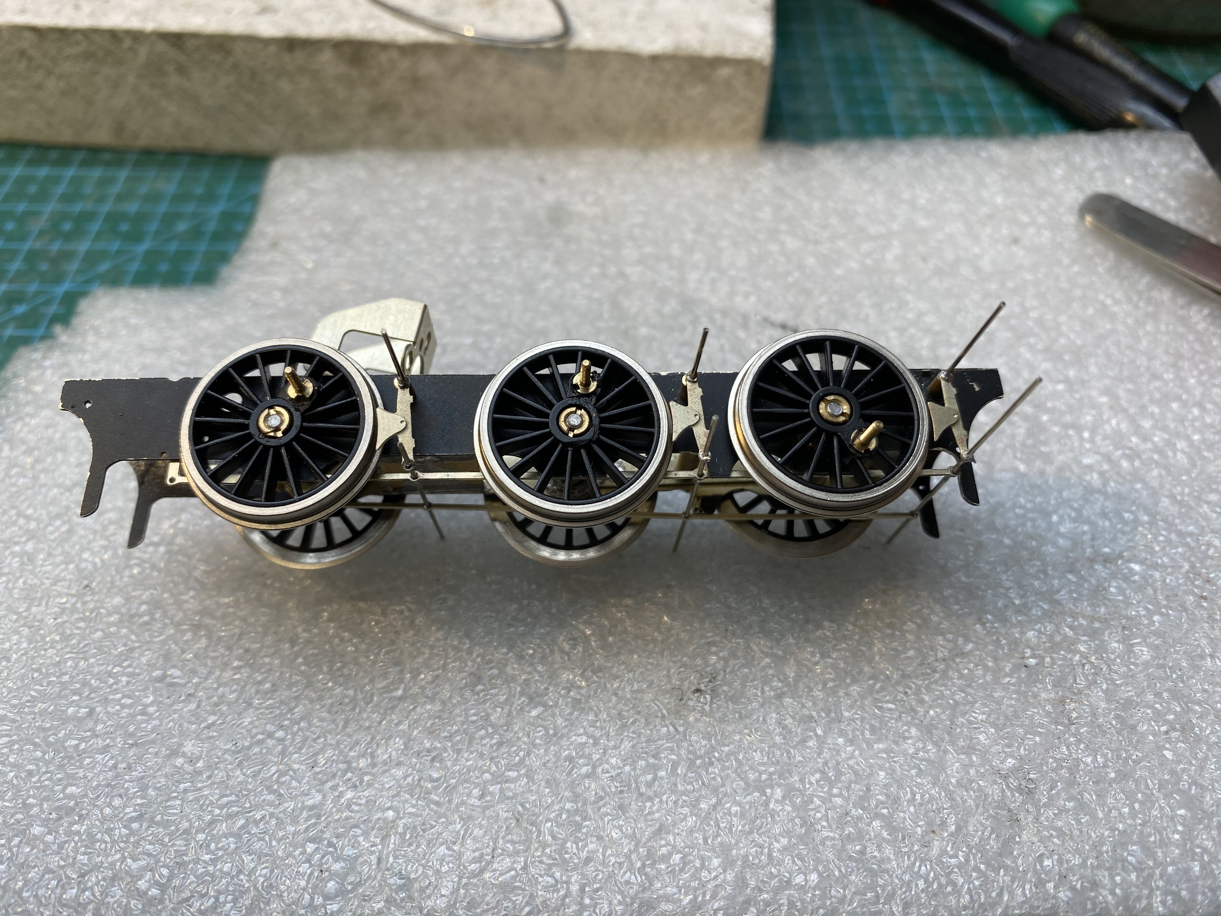
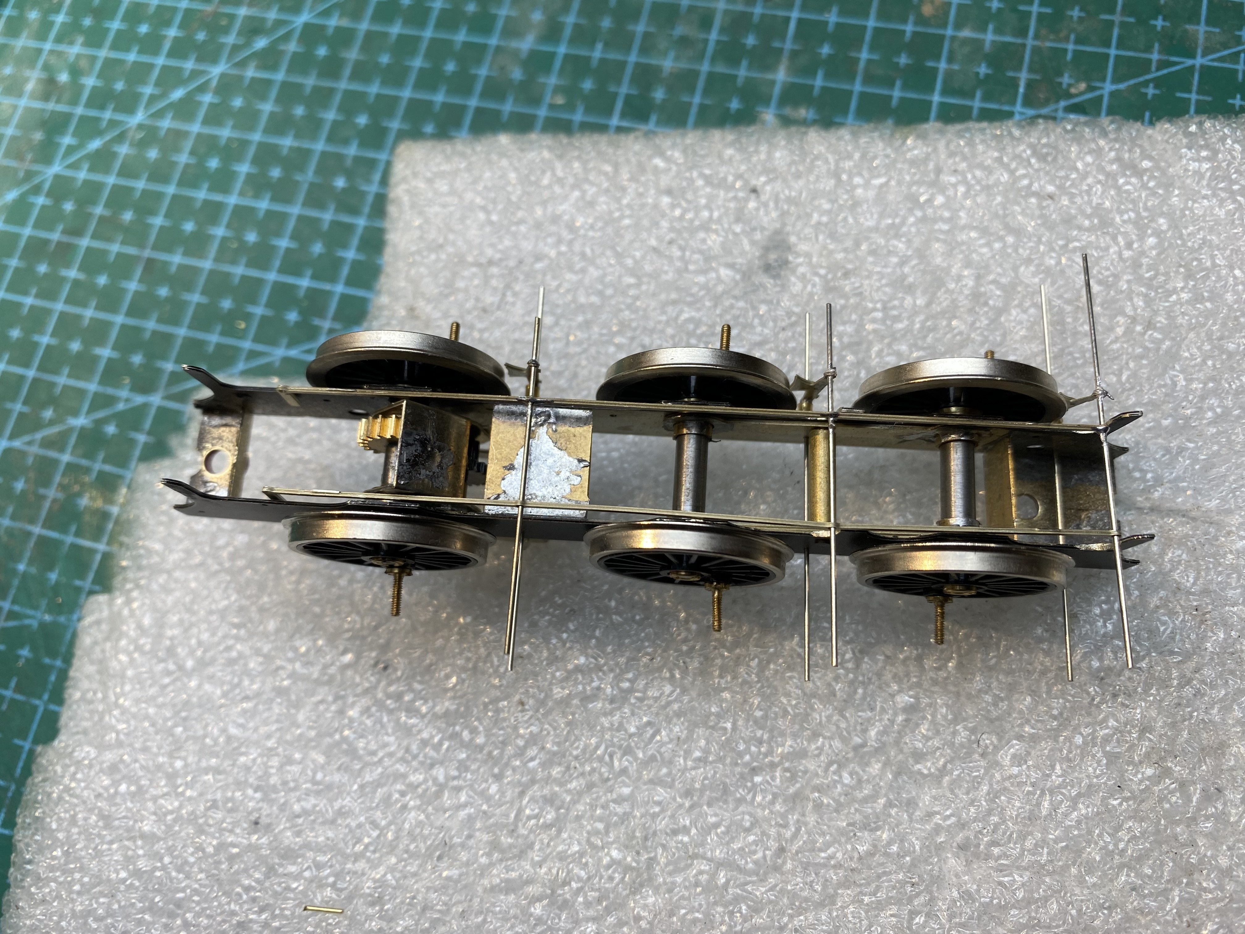
More on the reclamation of the K's Midland Railways Kirtley kit about which I posted back on 11 February. I think at last I've got a viable loco chassis. The intention is to build it with live chassis, picking up one side on the loco and the other on the tender. To that end, the original wheels were cleaned up, then 3 loco wheels and 3 tender wheels were shorted using etched spiders from ScaleLink. For the loco wheels, the central square hole was reamed out to a tight fit on the 1/8'' plain axles. The legs are soldered to the back of the wheel rims. Chassis frames are in 16 thou nickel silver. No detail needed since they won't be seen on this outside framed loco. Hornblocks from High Level. RoadRunner Compact+ gearbox and iron core motor, also from High Level. Outside cranks with extended axles from Alan Gibson (Code 5000). Coupling rods are ex-Lanarkshire Models, now available from High Level (Fowler 4F, 8' + 8' 6"). Just noticed on the pic above that a couple of crankpin nuts on the far side are about to ping off into the ether! The wheels' centre holes are worn and it's been difficult to secure them on the axles. Superglue is doing the job at the moment. We'll see how long that lasts. IMG_4773.MOV Next job will be to arrange chassis mounts inside the K's whitemetal bodies. Alan
- 860 replies
-
- 10
-

-

-
Clogherhead - A GNR(I) Seaside Terminus
Tullygrainey replied to Patrick Davey's topic in Irish Model Layouts
Great lineup Patrick. -
Sorted now David. Only took three quarters of an hour First, while trying to adjust the bottom soldered joint the whole rail came adrift. Then predictably, it pinged off the tweezers straight into the maw of the carpet monster. Actually I think I also have a bench monster. So I had to make a new one. Another member of the 'little things sent to try us club'
-
You're right! Well spotted David. Didn't notice that. Because I made the various sections separable, I couldn't solder the bottom of the handrails into holes in the running plate. Instead they're bent at right angles near the bottom and soldered to the bunker floor. That one will need desoldered and moved in a bit at the bottom.
-
Good luck with this one David. I'll enjoy seeing it go together. I'd love to have a go at one of those Tyrconnel kits but it would have to sit a shelf if I ever did, there being no suitable track hereabouts. Yet
-
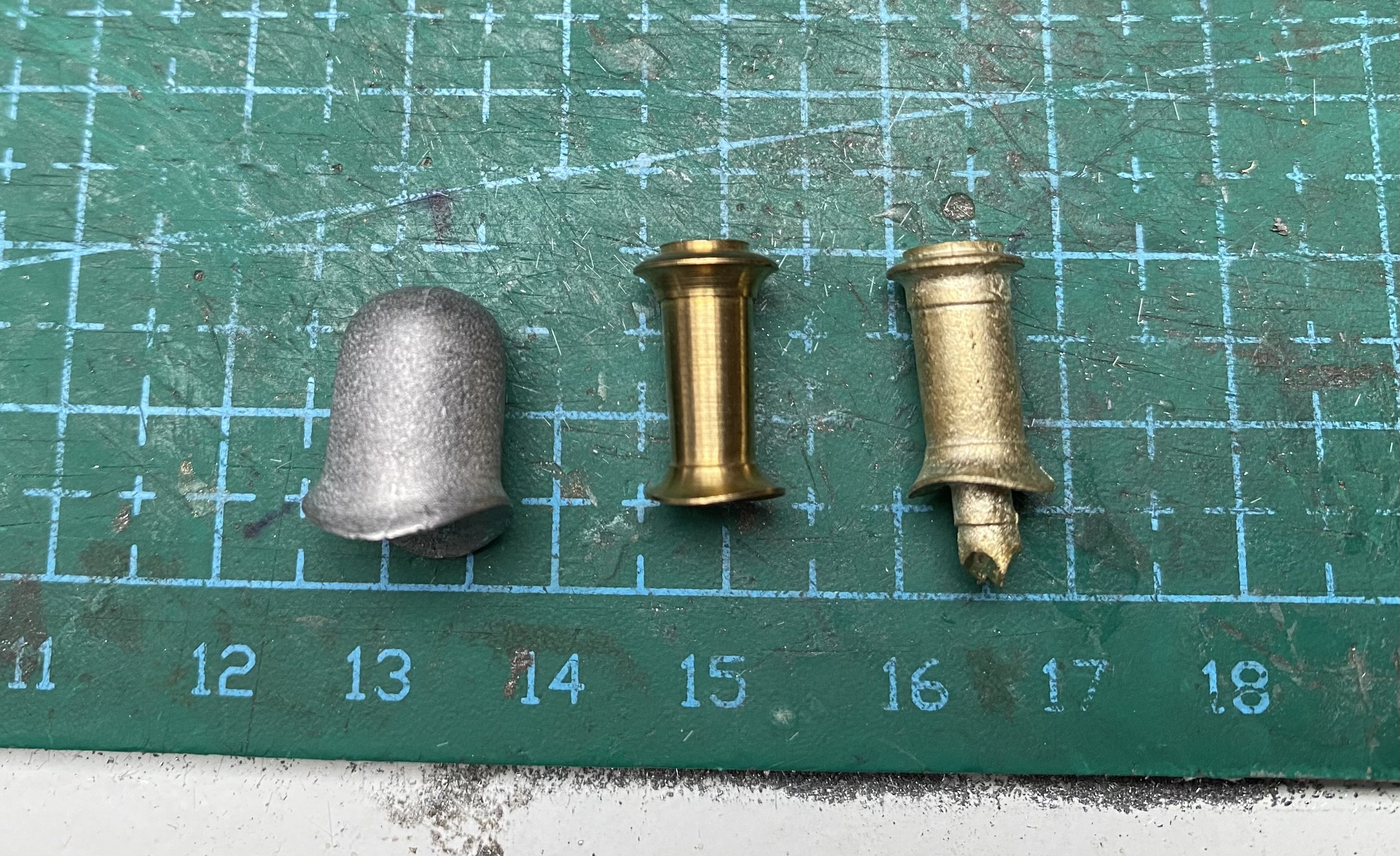
From left to right: Dome from the kit. I would agree it's ok. Turned brass chimney from Kieran's bits box. Origin? Around 14.5mm tall. Cast brass Alan Gibson chimney (4M730). Around 14.3mm tall Not sure yet which is better. Like you, I suspect there were variations across the class and over time so I'm not going to be too doctrinaire about it. I'll use the one that looks best.
-
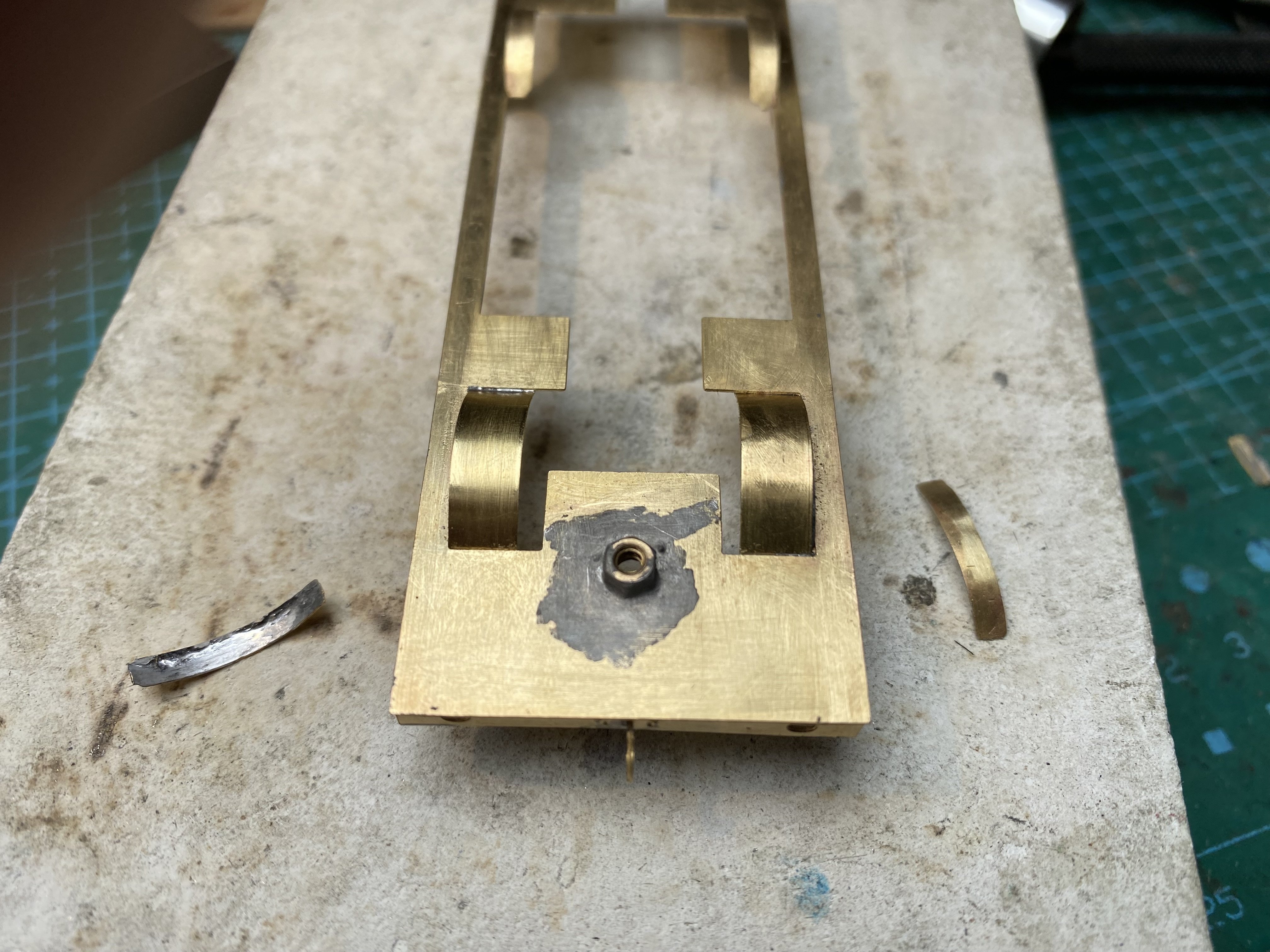
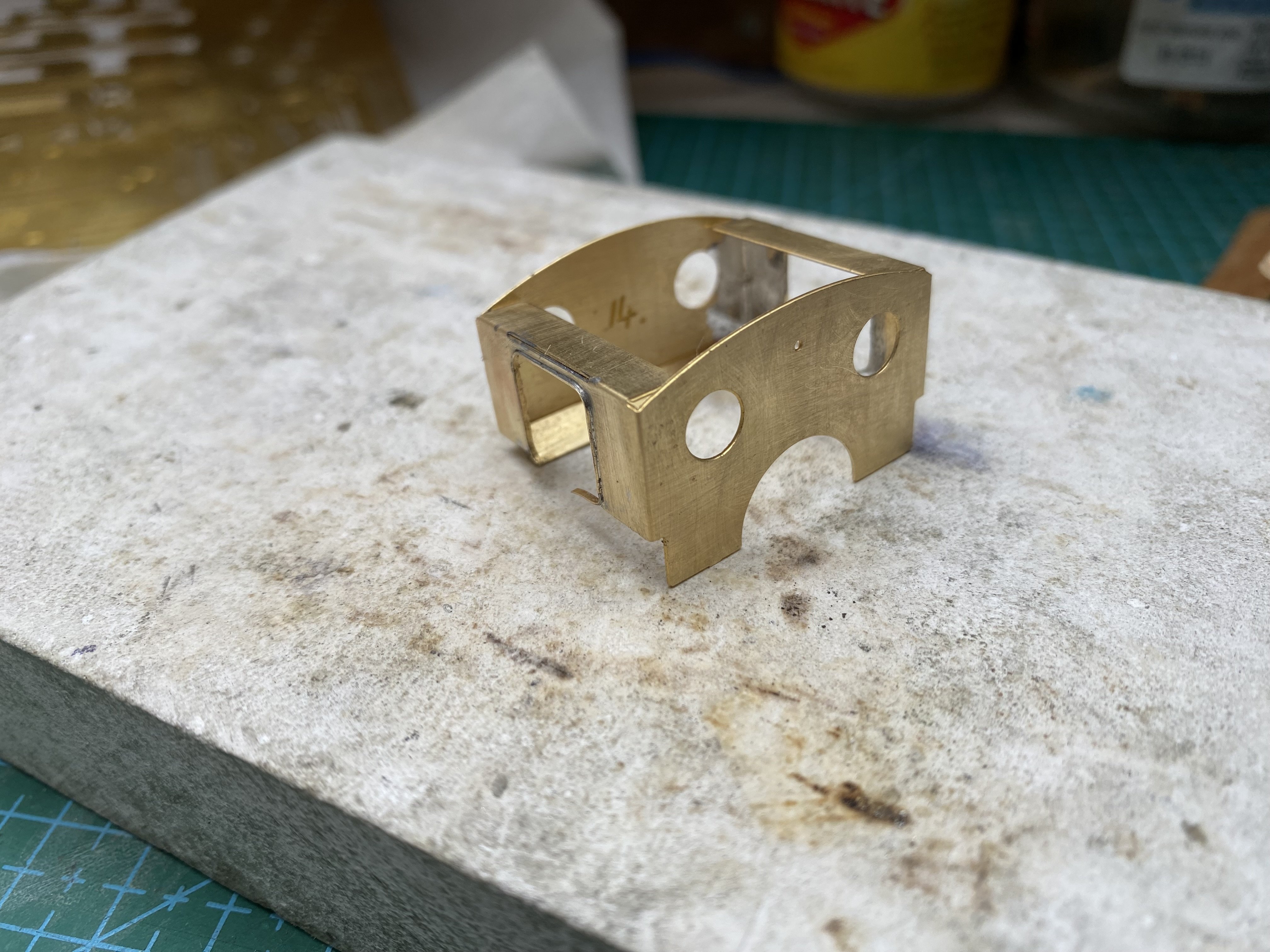
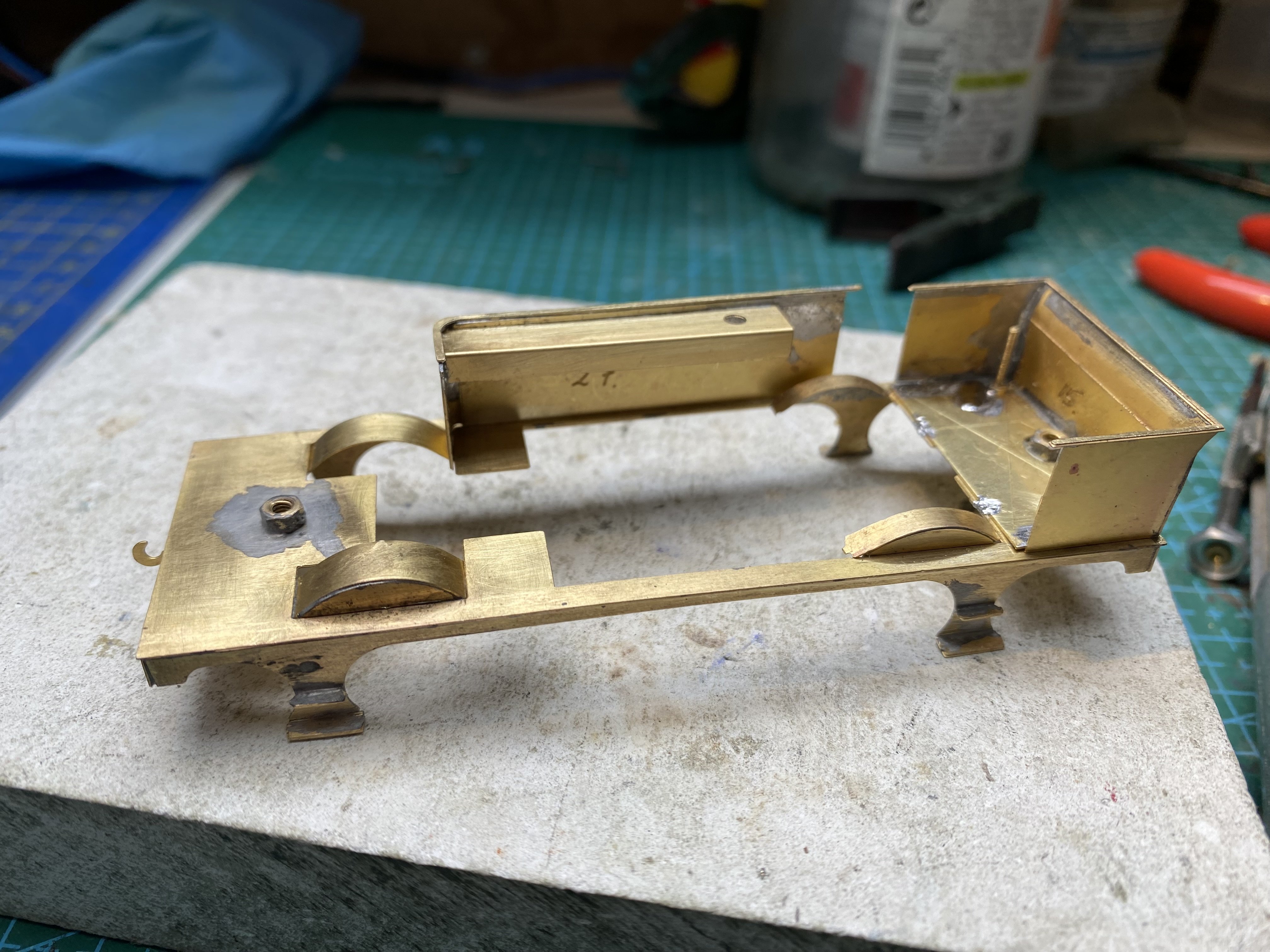
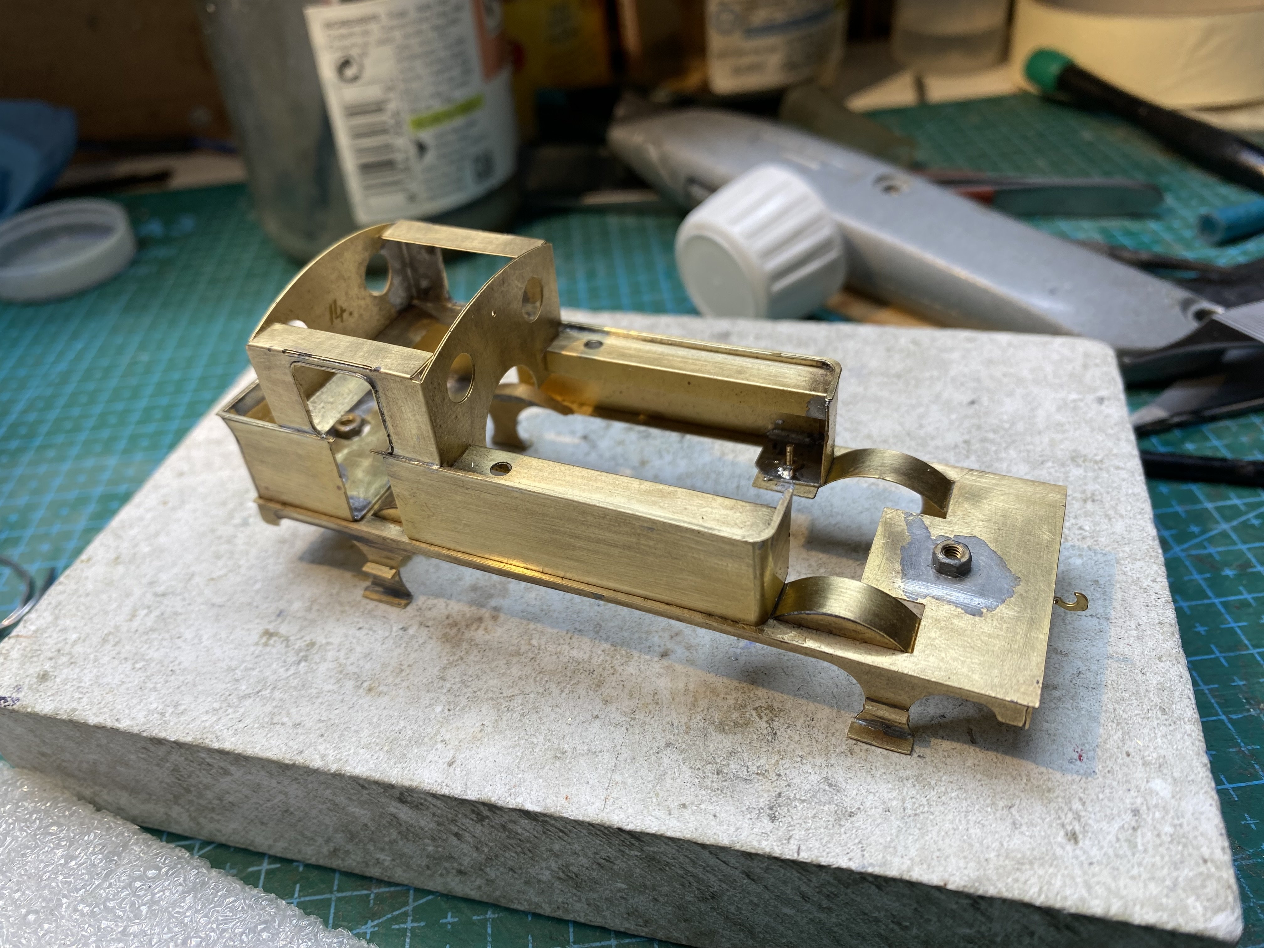
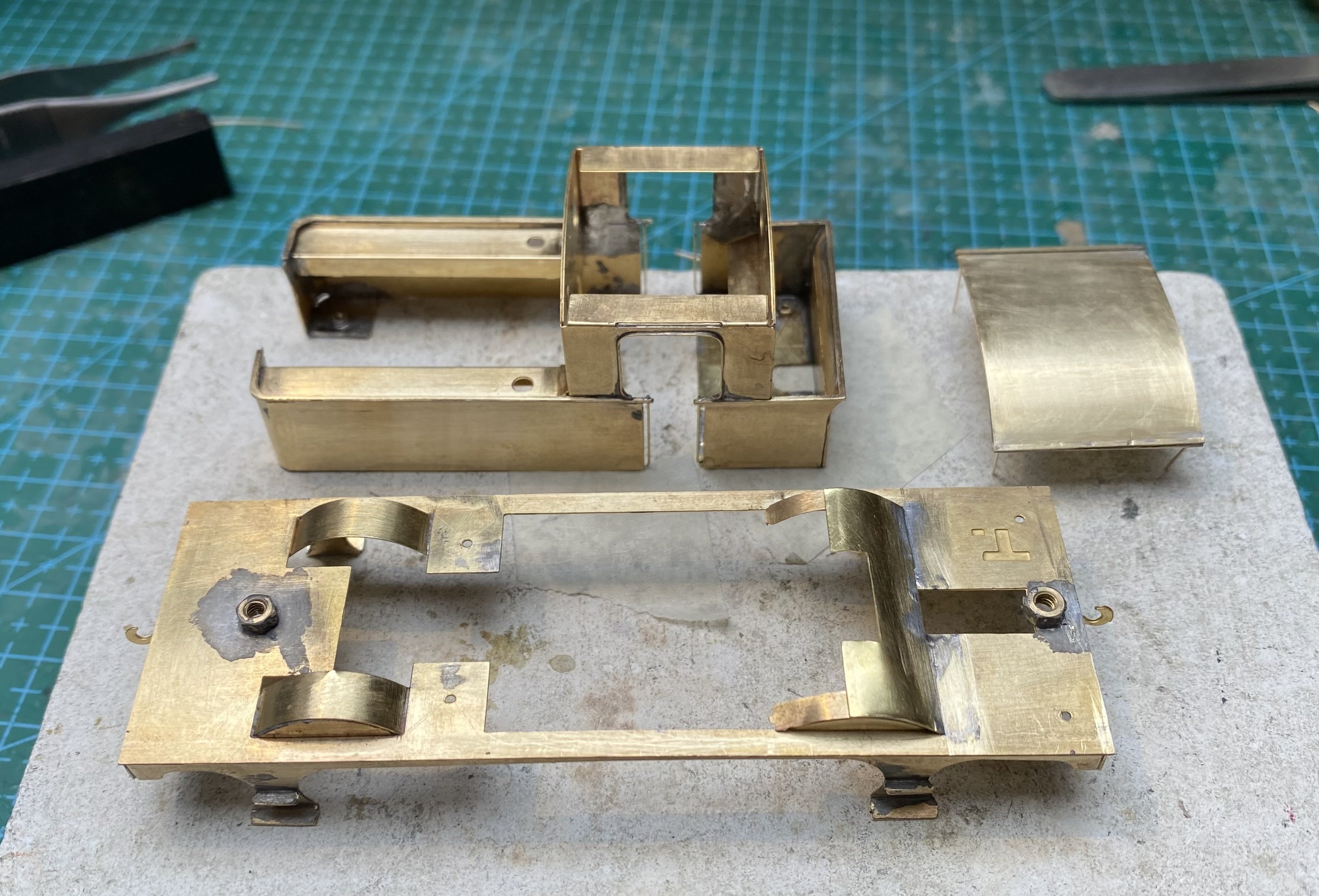
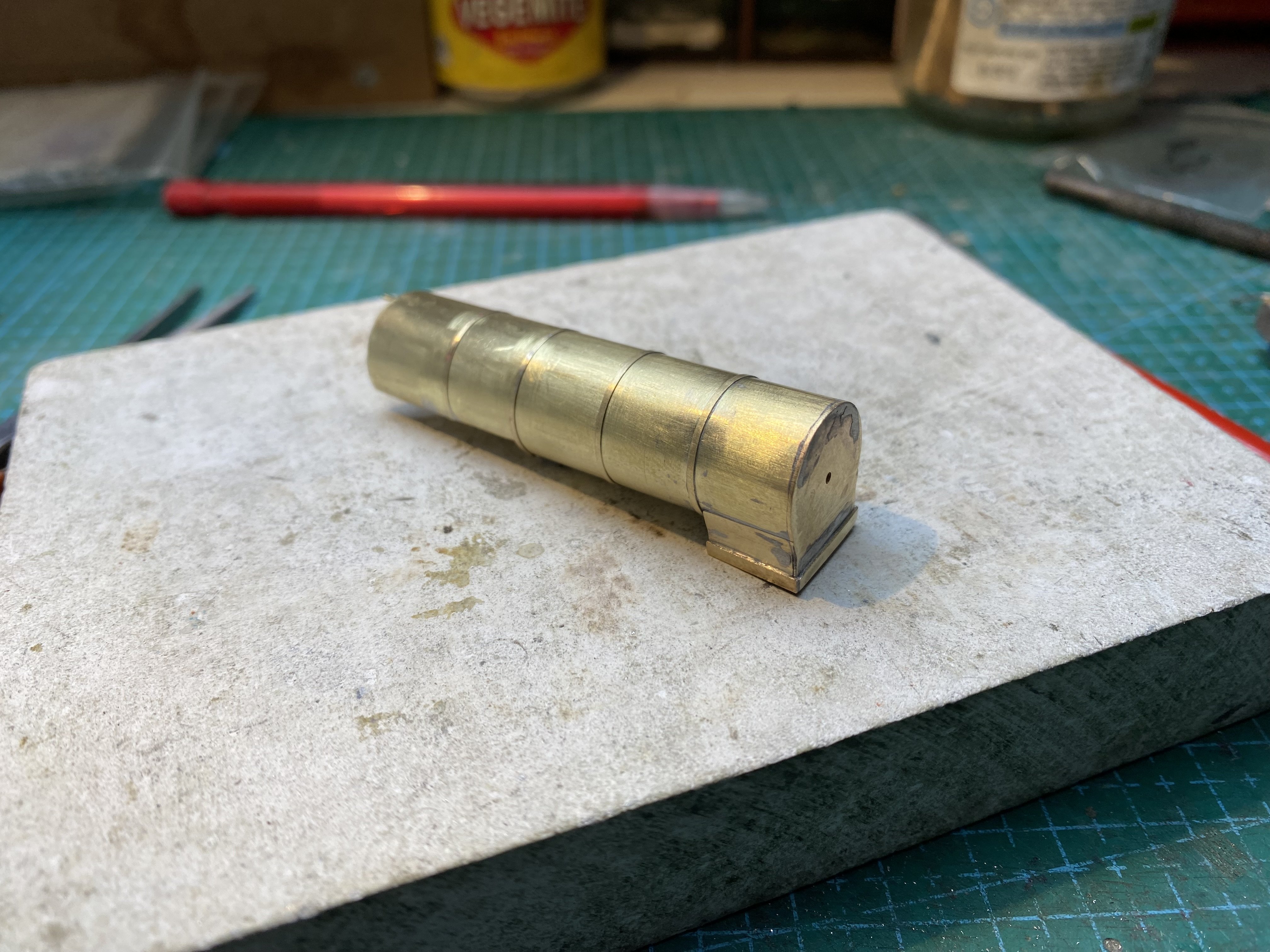
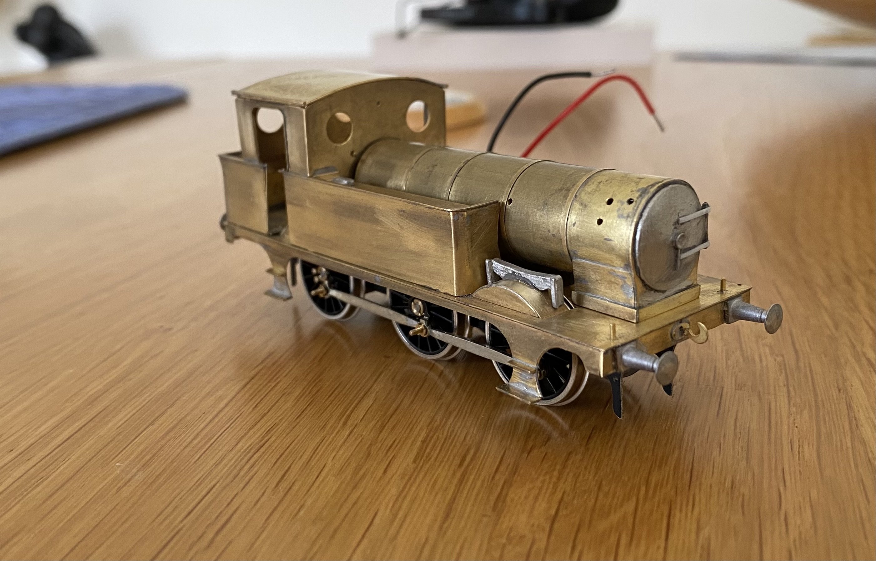
More T26. Taking a lead from Paul, I made wider splasher tops for the front axle in an attempt to disguise the OO gauge wheel spacing. It's certainly helped. A bit. The cab is a fold up design, front and sides, with the rear sheet soldered to this. Attaching the cab beading was a delicate task as was the beading on the bunker and tanks. Cab, bunker and tanks are soldered together into a single unit. This needs a bit of to and fro to get everything lined up and properly spaced. The instructions suggest soldering bunker and tanks to the running plate and there's no real reason not to do this. However, most of my BCDR locos were built as sub-sections which bolt together, which helps with painting and lining later. It's an approach I first came across in building Judith Edge kits and I've done it here too. There are two 14BA captive nuts in the back corners of the bunker and one at the front of each tank. Four 14BA bolts hold the whole structure tightly down onto the running plate. The boiler supplied with the kit is a heavy duty bit of brass tube. I got through 3 piercing saw blades cutting a clearance for the motor and gearbox. Soldering things to it was an even bigger challenge. It needed a lot of heat and plenty of time to get the solder melting and the whole thing was too hot to touch for about a minute after each task. The Resistance Soldering Unit came in handy to effectively tack boiler bands in place. Some detail bits added. The whitemetal castings were attached with 5 minute epoxy. More work needed on the chassis now - brakes and pickups. Always a joy to do Alan
- 860 replies
-
- 10
-
-
-
Looking really well. That's a great combination of industrial buildings in the background. Very convincing
-
Innovative stuff! Well done. And a new use for Polyfilla into the bargain
-
"Voiding the Warranty" - Mol's experiments in 21mm gauge
Tullygrainey replied to Mol_PMB's topic in Irish Models
I notice that ScaleLink, who produce Markit/Romford-type wheels only sell crankpins if you also buy their wheels. https://www.scalelink.co.uk/acatalog/Locomotive_Driving_Wheels_.html -
"Voiding the Warranty" - Mol's experiments in 21mm gauge
Tullygrainey replied to Mol_PMB's topic in Irish Models
Some very fine engineering going on here Paul. Once made, I imagine it will be endlessly useful in the future making all the effort worthwhile. -
Custom 3D printed Aluminium class Peckett “Tyrone”
Tullygrainey replied to Jamie Davis's topic in Irish Models
Great piece of work Jamie.- 5 replies
-
- 1
-

-
- 009
- narrow gauge
- (and 5 more)
-
Clogherhead - A GNR(I) Seaside Terminus
Tullygrainey replied to Patrick Davey's topic in Irish Model Layouts
Amm…. The one with the red engine?… the one with no engines? I think I detect an NCC 12inches/foot model amongst the 4mm/ft models -
"Voiding the Warranty" - Mol's experiments in 21mm gauge
Tullygrainey replied to Mol_PMB's topic in Irish Models
That’s a lot of work! -
"Voiding the Warranty" - Mol's experiments in 21mm gauge
Tullygrainey replied to Mol_PMB's topic in Irish Models
Gibson wheels and some 1/8” steel rod?